Conceptronic ADSL2+ Router & Modem Installation guide

Category
Routers
Type
Installation guide
Conceptronic CADSLR4+ Annex A/B
Version 4.1
July 2006
1
Table of Contents
Specification................................................................Error! Bookmark not defined.
Package Contents...................................................................................................... 5
Hardware Connecting................................................................................................. 6
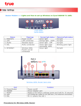
LED Indicators............................................................................................................ 7
General Setting........................................................................................................... 8
Advanced Setup....................................................................................................... 12
Setup................................................................................................................. 12
LAN Setup.................................................................................................. 12
LAN Configuration...................................................................................... 12
Ethernet Switch.......................................................................................... 14
WAN Setup................................................................................................. 15
New Connection......................................................................................... 15
PPPoE Settings................................................................................... 18
PPPoA Settings................................................................................... 20
Static Settings ..................................................................................... 22
DHCP Settings.................................................................................... 23
Bridge Settings.................................................................................... 24
CLIP Settings ...................................................................................... 25
Modem....................................................................................................... 26
ADVANCED....................................................................................................... 27
UPnP.......................................................................................................... 27
SNTP.......................................................................................................... 28
Port Forwarding.......................................................................................... 29
DMZ ........................................................................................................... 30
Custom Port Forwarding ............................................................................ 31
IP Filter....................................................................................................... 32
Custom IP Filters........................................................................................ 32
LAN Clients ................................................................................................ 34
LAN Isolation.................................................Error! Bookmark not defined.
TR-068 WAN Access.....................................Error! Bookmark not defined.
Bridge Filters.................................................Error! Bookmark not defined.
Dynamic DNS Client................................................................................... 35
IGMP Proxy................................................................................................ 36
Static Routing............................................................................................. 37
Policy Routing ...............................................Error! Bookmark not defined.
Ingress ..........................................................Error! Bookmark not defined.
2
Egress...........................................................Error! Bookmark not defined.
Shaper........................................................................................................ 38
Web Access Control................................................................................... 39
SSH Access Control................................................................................... 40
TOOLS.............................................................................................................. 41
System Commands.................................................................................... 41
Remote Log-Router.................................................................................... 42
User Management...................................................................................... 43
Update Gateway............................................Error! Bookmark not defined.
Ping Test .................................................................................................... 44
Modem Test................................................................................................ 45
STATUS............................................................................................................. 46
Network Statistics....................................................................................... 46
Connection Status...................................................................................... 47
DHCP Clients............................................................................................. 47
Modem Status ............................................................................................ 48
Product Information.................................................................................... 48
System Log................................................................................................ 49
HELP................................................................................................................. 50
Firewall Help .............................................................................................. 50
Bridge Filter Help........................................................................................ 50
LAN Clients Help........................................................................................ 52
LAN Configuration Help.............................................................................. 52
PPP Connection Help................................................................................. 53
UPnP Help.................................................................................................. 53
IP QoS Help ............................................................................................... 54
RIP Help..................................................................................................... 54
Troubleshooting................................................................................................. 55
Appendix ........................................................................................................... 62
3
ADSL 2/2+ 4 Port Router
Line Connection
RJ-11(2 wires), RJ-45 (4 port)
ADSL Features
DMT modulation and demodulation
Tone detection for low power mode
ATM SAR performed in software driver
ITU 992.1 (G.dmt) Annex A, B,
ITU 992.2 (G.lite)
ITU 992.3 ADSL2 (G.dmt.bis)
ITU 992.5 ADSL2+
ANSI T1.413 Issue 2
Full-rate adaptive
modem
Maximum downstream rate of 24 Mbps (ADSL2+)
Maximum upstream rate of 1 Mbps
G.lite adaptive modem
Maximum downstream rate of 1.5 Mbps
Maximum upstream rate of 512 Kbps
WAN Mode Support
PPP over ATM (RFC 2364)
PPP over Ethernet (RFC 2516)
LAN Mode Support
Bridged/routed Ethernet over ATM (RFC 2684/1483)
Classical IP over ATM (RFC 1577) and PPP over
Ethernet (RFC 2516)
Bridge Mode Support
Ethernet to ADSL self-learning Transparent Bridging
(IEEE 802.1D)
Supports up to 128 MAC learning addresses
Router Mode Support
IP routing-RIPv2 (backward compatible with RIPv1)
Static routing
DHCP (Dynamic Host Configuration Protocol) Server
and Client
NAPT (Network Address and Port Translation)
NAT (Network Address Translation)
ICMP (Internet Control Message Protocol)
Simultaneous USB and Ethernet operation
IGMP (Internet Group Management Protocol)
Ethernet Features
Four RJ-45 connectors for 10/100 Mbps Ethernet LAN
connection,
DMZ function can be set up between them
Complies with IEEE 802.3u specification
Supports IEEE 802.3x Flow control in Full Duplex mode
Certification
CE,LVD
OS
WIN 98SE ; WIN 2000WIN MEWIN XP
System Requirement
PII-266 + 32M RAM
Power
External AC Power
Power ON/OFF switch (option)
Input: 90~120V or 200~240V, 50/60Hz
Output: 12VAC/800mA
LED Indication
Power, LAN1, LAN2, LAN3, LAN4, ADSL Link/Act
PCB SIZE
134mm×96.5mm
Software Upgrade
Upgrade by Ethernet Port
4
Application Diagram
Internet
ADSL
5
Package Contents
Conceptronic CADSLR4+ Annex A/B
CD-ROM containing Manual and USB Driver for one port router
Ethernet Cable (CAT5 UTP Straight-Through)
Telephone Cable (RJ11)
USB Cable only for one port router
Power Adapter (12VAC 800mA)
Quick Installation Guide
6
Hardware Connecting
Conceptronic CADSLR4+ Annex A/B ADSL modem
Factory Reset Button
USB Cable
connect to USB
port
RJ-45 connect to
computer Ethernet Port
Connect to Power
Adapter
Phone cable connect
to Splitter
Phone Cable connect
to wall phone jack
Factory Reset Button
Connect to Power
Adapter
RJ-45 connect to
computer Ethernet Port
Phone cable connect
to Splitter
Phone Cable connect
to wall phone jack
7
LED Indicators
The LED Indicators are located on the front of the unit, they are green in color. The
meanings are as follows:
Label Meaning Status Indicates
PWR Power On Power is on
Off Power is off
LAN LAN Flashing
Flashes when data is being sent or
received on the LAN connection.
On
Indicates a link to your LAN or Network
card is active.
Off
Indicates no link to LAN
USB On On USB initialize
ADSL Link Link
A valid ADSL connection.
Label Meaning Status Indicates
PWR Power On Power is on
Off Power is off
LAN 1/ LAN 2/
LAN 3/ LAN 4
LAN Link Flashing
Flashes when data is being sent or
received on the LAN connection.
On
Indicates a link to your LAN or Network
card is active.
Off
Indicates no link to LAN
ADSL Link Link
A valid ADSL connection.
Conceptronic CADSLR4+ Annex A/B
8
General Setting
1. Move your cursor as flowing sequence Start \ Settings \ Control Panel and
click Control Panel. Then double-click on the Network Connections
2. In the LAN or High-Speed Internet window, right-click on icon corresponding
to your network interface card (NIC) and select Properties.(This icon may be
labeled Local Area Connection).
Double Click
on this icon
9
3. In the General Tab of the Local Area Connection Properties menu. Highlight
Internet Protocol (TCP/IP) under “This connection uses the following items.”
by click on it once. Click on the Properties button.
4. Select Obtain an IP Address automatically: by clicking once in the circle.
Click OK button to confirm and save your changes, and the close the Control
Panel.
Select Obtain an
IP address
automatically
10
5. Release IP & Renew IP, then Check Default Gateway: 192.168.1.1.
6. Launch your PC web browser and enter the URL: http://192.168.1.1
7. In the User name/Password prompt, please type in Admin/Admin as default.
11
8. After Login procedure the Quick Start page will appear.
-
XSelect country from the drop-down list.
YSelect ISP from the drop-down list.
ZSelect Encapsulation from the drop-down list.
[The VPI and VCI value will automatically set up ok. Then click Next.
rIf you can’t find your ISP setting, please click Config.
1
2
3
5
4
12
Advanced Setup
Setup
The Setup section allows you to create new connections, edit existing connections,
and configure other basic settings.
LAN Setup
LAN Configuration
The following is displayed LAN Setup.
IP Address: Private IP address for connecting to a local private network (Default:
192.168.1.1).
Netmask: Netmask for the local private network (Default: 255.255.255.0).
Default Gateway: This field is optional. Enter in the IP address of the router on your
network.
Host Name: Required by some ISPs. If the ISP does not provide the Host name,
please leave it blank.
Domain Name: www.dynsns.org will provide you with a Domain Name. Enter this
name in the “Domain Name” field.
Enable DHCP Server: Enable or Disable DHCP Server.
13
Start IP: Sets the start IP address of the IP address pool.
End IP: Sets the end IP address of the IP address pool.
Lease time: The lease time is the amount of time of a network user will be allowed to
connect with DHCP server. If all fields are 0, the allocated IP address will be
effective forever.
Click Apply to complete the setup. Click Save All to save the changes.
14
Ethernet Switch
This Ethernet Switch Configuration page allows you to set value for data transfer;
Physical Port: There are five kinds of mode for data transfer (Auto)(10/Half
Duplex)(10/Full Duplex)(100/Half Duplex)(100/Full Duplex).
Click Apply to complete the setup. Click Save All to save the changes.
15
WAN Setup
New Connection
When working with wide area connections, the first thing you must do is to have the
handle of the connection. Once you have the handle for a Connection you must define
the PVC and protocol settings for it.
Name: Enter the name of your ISP. This information is for identification purposes only.
Type: There six kinds of method (PPPoE/ PPPoA/ Static/ DHCP/ Bridge/ CLIP).
Encapsulation: Select you encapsulation type. (Supplied by your ISP).
Username: Enter the username provided by your ISP.
Password: Enter the password provided by your ISP.
Idle Timeout: Idle timeout means the router will disconnect after being idle for a
preset amount of time. The default is 60 seconds. If you set the time to 0, the link
will remain always connected to the ISP.
Keep Alive: When the On Demand option is not enabled, this value specifies the time
to wait without being connected to your provider before terminating the
connection. To ensure that the link is always active, enter a 0 in this field. You
can also enter any positive integer value in this field.
Authentication: Set the required authentication protocol. (Auto/ CHAP/ PAP)
MTU: Maximum transmit unit the DSL connection can transmit. It is a negotiated value
that packets of no more than n bytes can be sent to the service provider. The
PPPoE interface default MTU is 1492 (max) and PPPoA default MTU is 1500
(max). The minimum MTU value is 64.
On Demand: Enables On Demand mode. The connection disconnects if no activity is
detected after the specified idle timeout value. When checked, this field enables
the following fields:
16
• Idle Timeout
• Host Trigger
• Valid Rx
Default Gateway: If checked, this WAN connection acts as the default gateway to the
Internet.
Enforce MTU: This feature is enabled by default. It forces all TCP traffic to conform
with PPP MTU by changing TCP maximum segment size to PPP MTU. If it is
disabled, you may have issues accessing some Internet sites.
Debug: Enables PPPoE connection debugging facilities. This option is used by ISP
technical support and ODM/OEM testers to simulate packets going through the
network from the WAN side.
PPP Unnumbered: PPP Unnumbered is a special feature. It enables the ISP to
designate a block of public IP addresses to the customer where it is statically
assigned on the LAN side. PPP Unnumbered is, in essence, like a bridged
connection.
LAN: The LAN field is associated with the PPP Unnumbered field and is enabled
when the PPP Unnumbered field is checked. You can specify the LAN group the
packets need to go to when the PPP Unnumbered feature is activated.
PVC: Permanent virtual circuit. This is a fixed virtual circuit between two users. It is
the public data network equivalent of a leased line. No call setup or clearing
procedures are needed.
VPI: If instructed to change this, type in the VPI value for the initial connection (using
PVC 0). Default = 0.
VCI: If instructed to change this, type in the VCI value for the initial connection (using
PVC 0). Default = 0.
QoS: Quality of Service type. Select CBR (Continuous Bit Rate) to specify fixed
(always-on) bandwidth for voice or data traffic. Select UBR (Unspecified Bit Rate)
for applications that are non-time sensitive, such as e-mail. Select VBR (Variable
Bit Rate) for burst traffic and bandwidth sharing with other applications.
PCR: Divide the DSL line rate (bps) by 424 (the size of an ATM cell) to find the Peak
Cell Rate (PCR). This is the maximum rate at which the sender can send cells.
SCR: The Sustain Cell Rate (SCR) sets the average cell rate (long-term) that can be
transmitted.
MBS: Maximum burst size, a traffic parameter that specifies the maximum number of
cells that can be transmitted at the Peak Cell Rate.
CDVT: Cell delay variation tolerance, the maximum amount of cell delay variation that
can be accommodated. Cell delay variation measures the random inter-arrival
times of cells within an ATM connection due to cell transfer delay caused by
buffering, multiplexing, and so on.
Auto PVC: Auto-Sensing permanent virtual circuit. The overall operation of the
17
auto-sensing PVC feature relies on end-to-end OAM pings to defined PVCs.
There are two groups of PVCs: customer default PVCs which are defined by the
OEM/ISP and the backup PVCs. The customer default must have 0/35 as the
first default PVC. The backup list of PVCs must be of the following VPI/VCI: 0/35,
8/35, 0/43, 0/51, 0/59, 8/43, 8/51, and 8/59. The list of PVCs are defined in XML
and is configurable. The Auto-Sensing PVC feature itself is also configurable in
that the auto-search mechanism can be disabled.
Upon DSL synchronization, end-to-end OAM pings will be conducted for every
defined PVCs. The result of the pings will be recorded in an array for later use to
determine the usability of the particular PVC for connectivity. This list helps the
PVC manage the available PVC for use, and needs to be synchronized with
connections made without Auto-Sensing PVC. Update to this list is performed for
any change in DSL synchronization.
During connection establishment, the PVC module will first search through the list
of defined default PVCs. If a PVC is found from the default list that is ping-able
and not in use, the PVC module will update for that particular PVC as in-use from
the list and continues processing. If a PVC is not found in the default, the backup
PVC list is used. If no PVC is found again, the module will let the end-user know
that no available VCC was found.
With the connection established, the PVC is stored in flash as the connection
default PVC. Therefore upon reboot, this PVC is automatically chosen as the
PVC for that connection. This saved PVC in environment space of flash overrides
the PVC connection saved in XML configuration space of flash for that
connection. During the connection establishment processing, the saved PVC will
be checked to see whether a connection can be made with the PVC. If the PVC is
OAM ping-able, the connection process continues. If the PVC is not OAM
ping-able, the search for an available PVC starts. The process of PVC selection
is the same as described above.
The list of default PVCs and backup PVCs need to be global for the management
of all connections, non Auto-Sensing PVC connection, as well as, Auto-Sensing
PVC connections. These lists allow the end-users to establish connectivity
without keeping track of the PVC used.
18
PPPoE Settings
1. At the Setup main page, click New Connection.
2. At the Type field select PPPoE.
3. In the Name field, enter a unique name for the PPPoE connection. The name
must not have spaces and cannot begin with numbers.
4. The Network Address Translation (NAT) and the Firewall options are enabled
by default. Leave these in the default mode.
Note—NAT enables the IP address on the LAN side to be translated to IP
address on the WAN side. If NAT is disabled, you cannot access the Internet.
5. If you want to enable VLAN, use the reference to configure the following fields:
• Sharing: Select VLAN to enable the VLAN ID and Priority Bits fields.
• VLAN ID: Enter the VLAN ID.
• Priority Bits: Select the priority bits of the VLAN.
6. In the PPP Settings section, enter values from DSL service provider or your ISP.
7. In the PVC Settings section, enter values for the VPI and VCI.
Note—Your DSL service provider or your ISP supplies these values.
8. Select the Quality of Service (QoS). Leave the default value if you are unsure or
if the ISP did not provide this information.
The PCR, SCR, MBS, and CDVT fields are enabled / disabled depending on the
QoS selection. Enter the values provided by the ISP or leave the defaults.
9. Click Apply to complete the connection setup.
Sharing The following options are available:
Disable: Disables connection sharing.
Enable: Enables connection sharing.
19
VLAN: The VLAN ID and Priority Bits fields are activated when VLAN is
selected, which enable you to create VLAN.
VLAN ID VLAN Identification. Multiple connections over the same PVC are
Supported, which requires the WAN network to have VLAN support and for
the DSLAMS and Routers on the ISP to handle VLAN Tags. Extended
support is also available, which allows multiple connections to be placed
over the single PVC without VLAN support (VLAN Tag of 0 is this special
case). In this mode of operation, a received packet is flooded on all the
connections that reside over it.
Priority
Bits
Priority is given to a VLAN connection from 0-7. All packets sent over the
VLAN connection have the Priority bits set to the configured value.
  • Page 1 1
  • Page 2 2
  • Page 3 3
  • Page 4 4
  • Page 5 5
  • Page 6 6
  • Page 7 7
  • Page 8 8
  • Page 9 9
  • Page 10 10
  • Page 11 11
  • Page 12 12
  • Page 13 13
  • Page 14 14
  • Page 15 15
  • Page 16 16
  • Page 17 17
  • Page 18 18
  • Page 19 19
  • Page 20 20
  • Page 21 21
  • Page 22 22
  • Page 23 23
  • Page 24 24
  • Page 25 25
  • Page 26 26
  • Page 27 27
  • Page 28 28
  • Page 29 29
  • Page 30 30
  • Page 31 31
  • Page 32 32
  • Page 33 33
  • Page 34 34
  • Page 35 35
  • Page 36 36
  • Page 37 37
  • Page 38 38
  • Page 39 39
  • Page 40 40
  • Page 41 41
  • Page 42 42
  • Page 43 43
  • Page 44 44
  • Page 45 45
  • Page 46 46
  • Page 47 47
  • Page 48 48
  • Page 49 49
  • Page 50 50
  • Page 51 51
  • Page 52 52
  • Page 53 53
  • Page 54 54
  • Page 55 55
  • Page 56 56
  • Page 57 57
  • Page 58 58
  • Page 59 59
  • Page 60 60
  • Page 61 61
  • Page 62 62
  • Page 63 63
  • Page 64 64
  • Page 65 65

Conceptronic ADSL2+ Router & Modem Installation guide

Category
Routers
Type
Installation guide

Ask a question and I''ll find the answer in the document

Finding information in a document is now easier with AI