Supermicro MBD-X9DRH-7F-O User manual
- Category
- Server/workstation motherboards
- Type
- User manual

USER’S MANUAL
Revision 1.0b
X9DRH-7F
X9DRH-iF
X9DRH-7TF
X9DRH-iTF

Manual Revision 1.0b
Release Date: Dec. 13, 2012
Unless you request and receive written permission from Super Micro Computer, Inc., you may not
copy any part of this document.
Information in this document is subject to change without notice. Other products and companies
referred to herein are trademarks or registered trademarks of their respective companies or mark
holders.
Copyright © 2012 by Super Micro Computer, Inc.
All rights reserved.
Printed in the United States of America
The information in this User’s Manual has been carefully reviewed and is believed to be accurate.
The vendor assumes no responsibility for any inaccuracies that may be contained in this document,
and makes no commitment to update or to keep current the information in this manual, or to notify
any person or organization of the updates. Please Note: For the most up-to-date version of this
manual, please see our Website at www.supermicro.com.
Super Micro Computer, Inc. ("Supermicro") reserves the right to make changes to the product
described in this manual at any time and without notice. This product, including software and docu-
mentation, is the property of Supermicro and/or its licensors, and is supplied only under a license.
Any use or reproduction of this product is not allowed, except as expressly permitted by the terms
of said license.
IN NO EVENT WILL SUPER MICRO COMPUTER, INC. BE LIABLE FOR DIRECT, INDIRECT,
SPECIAL, INCIDENTAL, SPECULATIVE OR CONSEQUENTIAL DAMAGES ARISING FROM THE
USE OR INABILITY TO USE THIS PRODUCT OR DOCUMENTATION, EVEN IF ADVISED OF
THE POSSIBILITY OF SUCH DAMAGES. IN PARTICULAR, SUPER MICRO COMPUTER, INC.
SHALL NOT HAVE LIABILITY FOR ANY HARDWARE, SOFTWARE, OR DATA STORED OR USED
WITH THE PRODUCT, INCLUDING THE COSTS OF REPAIRING, REPLACING, INTEGRATING,
INSTALLING OR RECOVERING SUCH HARDWARE, SOFTWARE, OR DATA.
Any disputes arising between the manufacturer and the customer shall be governed by the laws of
Santa Clara County in the State of California, USA. The State of California, County of Santa Clara
shall be the exclusive venue for the resolution of any such disputes. Supermicro's total liability for
all claims will not exceed the price paid for the hardware product.
FCC Statement: This equipment has been tested and found to comply with the limits for a Class
A digital device pursuant to Part 15 of the FCC Rules. These limits are designed to provide
reasonable protection against harmful interference when the equipment is operated in a commercial
environment. This equipment generates, uses, and can radiate radio frequency energy and, if not
installed and used in accordance with the manufacturer’s instruction manual, may cause harmful
interference with radio communications. Operation of this equipment in a residential area is likely
to cause harmful interference, in which case you will be required to correct the interference at your
own expense.
California Best Management Practices Regulations for Perchlorate Materials: This Perchlorate
warning applies only to products containing CR (Manganese Dioxide) Lithium coin cells. “Perchlorate
Material-special handling may apply. See www.dtsc.ca.gov/hazardouswaste/perchlorate”.
WARNING: Handling of lead solder materials used in this
product may expose you to lead, a chemical known to
the State of California to cause birth defects and other
reproductive harm.

Preface
This manual is written for system integrators, PC technicians and
knowledgeable PC users. It provides information for the installation and use of the
X9DRH-7F/-iF/-7TF/-iTF motherboard.
About This Motherboard
The Super X9DRH-7F/-iF/-7TF/-iTF motherboard supports dual Intel E5-2600 Se-
ries (Socket R) processors and Intel QPI (QuickPath Interface) Technology (V.1.1),
providing point-to-point connections with transfer speeds of up to 8.0 TG/s. With the
C602 PCH built in, the X9DRH series motherboard supports Intel® Management En-
gineer (ME), Rapid Storage Technology, Digital Media Interface (DMI), PCI-E Gen.
3.0, and up to 1600 MHz DDR3 memory. These features greatly enhance system
performance for high-end server platforms. Please refer to our Website (http://www.
supermicro.com) for processor and memory support updates.
Manual Organization
Chapter 1 describes the features, specications and performance of the mother-
board. It also provides detailed information about the Intel C602 PCH.
Chapter 2 provides hardware installation instructions. Read this chapter when
installing the processor, memory modules, and other hardware components into
the system. If you encounter any problems, see Chapter 3, which describes
troubleshooting procedures for video, memory, and system setup stored in CMOS.
Chapter 4 includes an introduction to BIOS, and provides detailed information on
running the CMOS Setup utility.
Appendix A provides BIOS Error Beep Codes.
Appendix B lists software installation instructions.
Preface
iii

iv
Conventions Used in the Manual
Pay special attention to the following symbols for proper system installation and to
prevent damage to the system or injury to yourself:
Warning: Important information given to ensure proper system installation or to prevent
damage to the components or injury to yourself.
Note: Additional information given to differentiate various models or to
provides information for correct system setup.
X9DRH-7F/-iF/-7TF/-iTF Motherboard User’s Manual

Preface
v
Contacting Supermicro
Headquarters
Address: Super Micro Computer, Inc.
980 Rock Ave.
San Jose, CA 95131 U.S.A.
Tel: +1 (408) 503-8000
Fax: +1 (408) 503-8008
Email: [email protected] (General Information)
[email protected] (Technical Support)
Web Site: www.supermicro.com
Europe
Address: Super Micro Computer B.V.
Het Sterrenbeeld 28, 5215 ML
's-Hertogenbosch, The Netherlands
Tel: +31 (0) 73-6400390
Fax: +31 (0) 73-6416525
Email: [email protected] (General Information)
[email protected] (Technical Support)
[email protected] (Customer Support)
Asia-Pacic
Address: Super Micro Computer, Inc.
4F, No. 232-1, Liancheng Rd
Chung-Ho Dist., New Taipei City 235
Taiwan
Tel: +886-(2) 8226-3990
Fax: +886-(2) 8226-3991
Web Site: www.supermicro.com.tw
Technical Support:
Email: [email protected]
Tel: +886-(2)-8226-3990

vi
Table of Contents
Preface
Chapter 1 Overview
1-1 Overview ......................................................................................................... 1-1
1-2 Processor and Chipset Overview...................................................................1-11
1-3 Special Features ........................................................................................... 1-12
1-4 PC Health Monitoring .................................................................................... 1-12
1-5 ACPI Features ............................................................................................... 1-13
1-6 Power Supply ................................................................................................ 1-13
1-7 Super I/O ....................................................................................................... 1-14
1-8 Advanced Power Management ..................................................................... 1-14
Intel
®
Intelligent Power Node Manager (NM) (Available when the NMView
utility is installed in the system) .................................................................... 1-14
Manageability Engine (ME) ........................................................................... 1-15
1-9 Overview of the Nuvoton WPCM450 Controller ........................................... 1-15
Other Features Supported by the WPCM BMC Controller ........................... 1-15
Chapter 2 Installation
2-1 Standardized Warning Statements ................................................................. 2-1
2-2 Static-Sensitive Devices .................................................................................. 2-4
2-3 Processor and Heatsink Installation................................................................ 2-5
Installing the LGA2011 Processor ................................................................. 2-5
Installing a Passive CPU Heatsink ................................................................. 2-9
Removing the Heatsink ................................................................................. 2-10
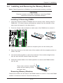
2-4 Installing and Removing the Memory Modules ..............................................2-11
Installing & Removing DIMMs ........................................................................2-11
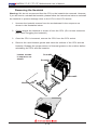
Removing Memory Modules ..........................................................................2-11
2-5 Motherboard Installation ................................................................................ 2-15
Tools Needed ................................................................................................ 2-15
Location of Mounting Holes .......................................................................... 2-15
Installing the Motherboard ............................................................................ 2-16
2-6 Control Panel Connectors and I/O Ports ...................................................... 2-17
Back Panel Connectors and I/O Ports .......................................................... 2-17
Back Panel I/O Port Locations and Denitions ........................................... 2-17
Universal Serial Bus (USB) ...................................................................... 2-18
Serial Ports ............................................................................................... 2-19
Video Connection ..................................................................................... 2-19
Ethernet Ports .......................................................................................... 2-20
X9DRH-7F/-iF/-7TF/-iTF Motherboard User’s Manual

vii
Table of Contents
Front Control Panel ....................................................................................... 2-21
Front Control Panel Pin Denitions............................................................... 2-22
NMI Button ............................................................................................... 2-22
Power LED .............................................................................................. 2-22
HDD LED .................................................................................................. 2-23
NIC1/NIC2 LED Indicators ....................................................................... 2-23
Overheat (OH)/Fan Fail LED.................................................................... 2-24
Power Fail LED ........................................................................................ 2-24
Reset Button ........................................................................................... 2-25
Power Button ........................................................................................... 2-25
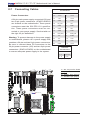
2-7 Connecting Cables ........................................................................................ 2-26
Power Connectors ................................................................................... 2-26
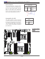
Fan Headers ............................................................................................. 2-27
Chassis Intrusion ..................................................................................... 2-27
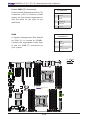
Internal Speaker ....................................................................................... 2-28
Overheat/Fan Fail LED ............................................................................ 2-28
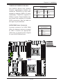
TPM Header/Port 80 Header ................................................................... 2-29
Standby Power ......................................................................................... 2-29
Power SMB (I
2
C) Connector .................................................................... 2-30
IPMB ......................................................................................................... 2-30
T-SGPIO1/2/T-SGPIO-S Headers ............................................................ 2-31
SATA DOM Power Connector .................................................................. 2-31
Battery Backup Unit (Optional for the X9DRH-7F/7TF Only) .................. 2-32
Onboard CMOS Battery ........................................................................... 2-32
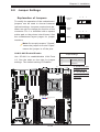
2-8 Jumper Settings ........................................................................................... 2-33
Explanation of Jumpers ................................................................................ 2-33
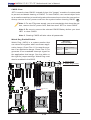
LAN1/LAN2 Enable/Disable ..................................................................... 2-33
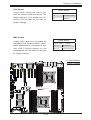
CMOS Clear ............................................................................................. 2-34
Watch Dog Enable/Disable ...................................................................... 2-34
VGA Enable .............................................................................................. 2-35
BMC Enable ............................................................................................ 2-35
SAS Enable .............................................................................................. 2-36
2-9 Onboard LED Indicators ............................................................................... 2-38
GLAN LEDs .............................................................................................. 2-38
IPMI Dedicated LAN LEDs ....................................................................... 2-38
Onboard Power LED ............................................................................... 2-39
BMC Heartbeat LED ................................................................................ 2-39
SAS Activity LED ...................................................................................... 2-40

viii
SAS Fault LED ......................................................................................... 2-40
2-10 Serial ATA Connections ................................................................................. 2-41
Serial ATA Ports........................................................................................ 2-41
SAS2 Ports (X9DRH-7F Only) ................................................................. 2-41
Chapter 3 Troubleshooting
3-1 Troubleshooting Procedures ........................................................................... 3-1
3-2 Technical Support Procedures ........................................................................ 3-4
3-3 Frequently Asked Questions ........................................................................... 3-5
3-4 Returning Merchandise for Service................................................................. 3-6
Chapter 4 BIOS
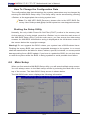
4-1 Introduction ...................................................................................................... 4-1
Starting BIOS Setup Utility .............................................................................. 4-1
How To Change the Conguration Data ......................................................... 4-2
Starting the Setup Utility ................................................................................. 4-2
4-2 Main Setup ...................................................................................................... 4-2
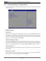
4-3 Advanced Setup Congurations...................................................................... 4-4
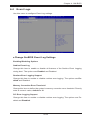
4-4 Event Logs .................................................................................................... 4-25
4-5 IPMI ............................................................................................................... 4-27
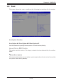
4-6 Boot ............................................................................................................... 4-29
4-7 Security ......................................................................................................... 4-30
4-8 Save & Exit ................................................................................................... 4-31
Appendix A BIOS Error Beep Codes
A-1 BIOS Error Beep Codes .................................................................................A-1
Appendix B Software Installation Instructions
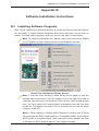
B-1 Installing Software Programs ..........................................................................B-1
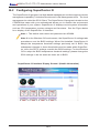
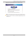
B-2 Conguring SuperDoctor III ............................................................................B-2
X9DRH-7F/-iF/-7TF/-iTF Motherboard User’s Manual

Chapter 1: Overview
1-1
Chapter 1
Overview
1-1 Overview
Checklist
Congratulations on purchasing your computer motherboard from an acknowledged
leader in the industry. Supermicro boards are designed with the utmost attention to
detail to provide you with the highest standards in quality and performance.
Please check that the following items have all been included with your motherboard.
If anything listed here is damaged or missing, contact your retailer.
The following items are included in the retail box.
• One (1) Supermicro Mainboard
• Six (6) Serial ATA cables (CBL-0044Lx6) (for X9DRH-iF/iTF)
• Two (2) Serial ATA cables (CBL-0044Lx2) (for X9DRH-7F/7TF)
•Two (2) I-Pass to Serial ATA cables (CBL-097L-03) (for X9DRH-7F/7TF)
• One (1) I/O Shield Bracket (MCP-260-00042-0N)
• One (1) Supermicro CD containing drivers and utilities
• One (1) Quick Reference Guide (MNL#1306-QRG)
Note: For your system to work properly, please follow the links below to
download all necessary drivers/utilities and the user's manual for your
motherboard.
SMCI product manuals: http://www.supermicro.com/support/manuals/
Product Drivers and utilities: ftp://ftp.supermicro.com/
If you have any questions, please contact our support team at support@supermicro.
com.

1-2
X9DRH-7F/-iF/-7TF/-iTF Motherboard User’s Manual
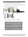
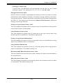
Motherboard Image
Note: All graphics shown in this manual were based upon the latest PCB
Revision available at the time of publishing of the manual. The motherboard
you've received may or may not look exactly the same as the graphics
shown in this manual.

Chapter 1: Overview
1-3
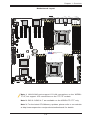
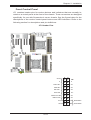
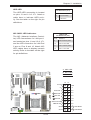
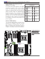
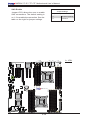
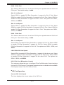
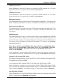
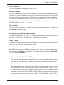
Motherboard Layout
Note 1: LAN1/LAN2 ports support 1G LAN connections on the X9DRH-
7F/-iF, but support 10G connections on the 7TF/iTF models.
Note 2: SAS 0~3/SAS 4~7 are available on the X9DRH-7F/-7TF only.
Note 3: For the latest CPU/Memory updates, please refer to our website
at http://www.supermicro.com/products/motherboard/ for details.
JS3
SAS4-7
JPWR1
JPWR2
JTPM1
T-SGPIO1
T-SGPIO2
FANB
FANA
FAN1
FAN6
JF1
JOH1
JWD
JPB1
JPG1
JPLAN1
JBT1
BT1
J21
JD1
JIPMB1
SP1
LE1
LEDS1
DM1
VGA
JSD1
LAN1
JSTBY1
S-SATA2
S-SATA3
S-SATA1
I-SATA1
I-SATA0
S-SATA0
P2 DIMM3A
P2 DIMM3B
P2 DIMM4A
P2 DIMM4B
P1 DIMMA1
P1 DIMMA2
P1 DIMMB1
P1 DIMMB2
P1 DIMMD2
P1 DIMMD1
P1 DIMMC2
P1 DIMMC1
CPU1 SLOT1 PCI-E 3.0 x8
CPU2 SLOT4 PCI-E 3.0 x16
CPU2 SLOT6 PCI-E 3.0 x8
P2 DIMME1
P2 DIMME2
P2 DIMMF1
P2 DIMMF2
USB2/3
CPU2 SLOT7 PCI-E 3.0 x8
COM2
IPMI_LAN
FAN2
LAN2
COM1
USB0/1
P2-DIMMH2
P2-DIMMH1
P2-DIMMG2
P2-DIMMG1
Battery
JPIC21
BIOS
BMC CTRL
LAN CTRL
Intel IO Hub
LSI SAS
CTRL
SAS0-3
J22
X9DRH-7F/iF/7TF/iF
Rev. 1.02
CLOSE 1st
OPEN 1st
CLOSE 1st
OPEN 1st
CPU2
CPU1
CPU1 SLOT3 PCI-E 3.0 x8
KB/MS
FAN5
CPU2 SLOT5 PCI-E 3.0 x8
CPU1 SLOT2 PCI-E 3.0 x8
JI2C1
JI2C2
I-SATA4
I-SATA5
I-SATA2
I-SATA3
JL1
FP CTRL
JPS1
LEDS2
FAN4
FAN3
USB4/5
USB6
USB8/9
T-SGPIO-S

1-4
X9DRH-7F/-iF/-7TF/-iTF Motherboard User’s Manual
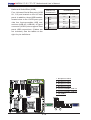
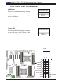
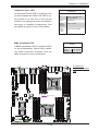
Notes:
•See Chapter 3 for detailed information on jumpers, I/O ports and JF1 front
panel connections.
•" " indicates the location of "Pin 1".
•Jumpers/LED Indicators not indicated are for testing only. Components that are
not documented in this manual are reserved for internal use only.
•Use the correct type of onboard CMOS battery as specied by the manufacturer.
Do not install the onboard battery upside down to avoid possible explosion.
X9DRH-7F/-iF/-7TF/-iTF Quick Reference
JS3
SAS4-7
JPWR1
JPWR2
JTPM1
T-SGPIO1
T-SGPIO2
FANB
FANA
FAN1
FAN6
JF1
JOH1
JWD
JPB1
JPG1
JPLAN1
JBT1
BT1
J21
JD1
JIPMB1
SP1
LE1
LEDS1
DM1
VGA
JSD1
LAN1
JSTBY1
S-SATA2
S-SATA3
S-SATA1
I-SATA1
I-SATA0
S-SATA0
P2 DIMM3A
P2 DIMM3B
P2 DIMM4A
P2 DIMM4B
P1 DIMMA1
P1 DIMMA2
P1 DIMMB1
P1 DIMMB2
P1 DIMMD2
P1 DIMMD1
P1 DIMMC2
P1 DIMMC1
CPU1 SLOT1 PCI-E 3.0 x8
CPU2 SLOT4 PCI-E 3.0 x16
CPU2 SLOT6 PCI-E 3.0 x8
P2 DIMME1
P2 DIMME2
P2 DIMMF1
P2 DIMMF2
USB2/3
CPU2 SLOT7 PCI-E 3.0 x8
COM2
IPMI_LAN
FAN2
LAN2
COM1
USB0/1
P2-DIMMH2
P2-DIMMH1
P2-DIMMG2
P2-DIMMG1
Battery
JPIC21
BIOS
BMC CTRL
LAN CTRL
Intel IO Hub
LSI SAS
CTRL
SAS0-3
J22
X9DRH-7F/iF/7TF/iF
Rev. 1.02
CLOSE 1st
OPEN 1st
CLOSE 1st
OPEN 1st
CPU2
CPU1
CPU1 SLOT3 PCI-E 3.0 x8
KB/MS
FAN5
CPU2 SLOT5 PCI-E 3.0 x8
CPU1 SLOT2 PCI-E 3.0 x8
JI2C1
JI2C2
I-SATA4
I-SATA5
I-SATA2
I-SATA3
JL1
FP CTRL
JPS1
LEDS2
FAN4
FAN3
USB4/5
USB6
USB8/9
T-SGPIO-S

Chapter 1: Overview
1-5
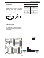
X9DRH-7F/-iF/-7TF/-iTF Jumpers
Jumper
Description Default Setting
JBT1
Clear CMOS See Chapter 3
JI
2
C1/JI
2
C2 SMB to PCI-E Slots Pins 2-3 (Normal)
JPB1 BMC Enable Pins 1-2 (Enabled)
JPG1 VGA Enable Pins 1-2 (Enabled)
JPLAN1 LAN1/LAN2 Enable Pins 1-2 (Enabled)
JPS1 SAS Enable Pins 1-2 (Enabled)
JWD1 Watch Dog Pins 1-2 (Reset)
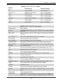
X9DRH-7F/-iF/-7TF/-iTF Connectors
Connectors Description
Battery Onboard CMOS Battery (See Chapter 3 for proper battery
disposal)
BBU (JS3) Battery Backup Unit for SAS Support (Optional for X9DRH-
7F/7TF)
CPU1 Slot1~3 CPU1 Slot1/Slot2/Slot3 PCI-E 3.0 x8 Slots
CPU2 Slot4 CPU2 Slot4 PCI-E 3.0 x16 Slot
CPU2 Slot5~7 CPU2 Slot6/Slot7 PCI-E 3.0 x8 Slots
COM1/COM2 Backplane COM Port1/Front Accessible COM2 Header
FAN1~FAN6,
FANA/B
CPU/System Fan Headers (Fans 1~6) & IO Slot Fan Head-
ers (FANA/FANB)
J22 ATX 24-Pin Power Connector (See Warning on Pg. 1-6.)
JD1 Speaker/Power LED Indicator
JF1 Front Panel Control Header
JIPMB1 4-pin External BMC I
2
C Header (for an IPMI Card)
JL1 Chassis Intrusion
JOH1 Overheat/Fan Fail LED
JPI
2
C1 Power Supply SMBbus I
2
C Header
JPWR1/JPWR2 12V 8-Pin Power Connectors (See Warning on Pg. 1-6.)
JSD1 SATA DOM (Disk_On_Module) Power Header
JSTBY1 Standby Power
JTPM1 TPM (Trusted Platform Module)/Port 80 Header
LAN1/2 GLAN Ports 1/2 for -7F/-iF, 10GLAN Ports 1/2 for -7TF/-
iTF)
(IPMI) LAN IPMI_Dedicated LAN
(I-)SATA 0/1 Intel SATA 3.0 Connectors 0/1 (from AHCI) (Available for
RAID 0,1, 5, 10 when used in conjunction with T-SPGIO1)

1-6
X9DRH-7F/-iF/-7TF/-iTF Motherboard User’s Manual
Warning!
To prevent damage to the power supply or motherboard, please use a power supply
that contains a 24-pin and two 8-pin power connectors. Be sure to connect these
power connectors to the 24-pin power connector (J22) and the 8-pin power connectors
(JPWR1/JPWR2) on the motherboard. Failure in doing so will void the manufacturer
warranty on your power supply and motherboard.
(I-)SATA 2~5 Intel SATA 2.0 Connectors (from AHCI): SATA2/3 (T-
SGPIO1) & SATA4/5 (T-SGPIO2) (Available for RAID 0, 1,
5, 10)
(S-)SATA 0~3 SATA 2.0 Connectors 0~3 from SCU (Storage Control Unit)
(Available for RAID 0, 1, 5, 10 when used in conjunction
with T-SPGIO-S)
SAS 0~3, 4~7 Serial_Attached_SCSI Connectors 0~3, 4~7 (X9DRH-7F/-
7TF)
SP1 Onboard Buzzer (Internal Speaker)
T-SGPIO1 Serial Link General_Purpose IO Headers (used in conjunc-
tion with I-SATA 0~3)
T-SGPIO2 Serial Link General_Purpose IO Header (used in conjunc-
tion with I-SATA 4/5)
T-SGPIO-S Serial Link General_Purpose IO Header (used in conjunc-
tion with S-SATA 0~3)
USB 0/1, 2/3 Back Panel USB 0/1, 2/3
USB4/5, 8/9 Front Panel Accessible USB 4/5, 8/9 Connections
USB 6 Front Panel Type A USB 6 Port
VGA Backpanel VGA Port (JVGA)
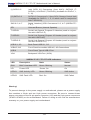
X9DRH-7F/-iF/-7TF/-iTF LED Indicators
LED Description State Status
DM1 BMC Heartbeat LED Green: Blinking Normal
LE1 Power LED Green: On On
LEDS1 SAS Activity LED Green: Blinking SAS Active
LEDS2 SAS Fault LED Red: On SAS Failed

Chapter 1: Overview
1-7
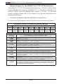
Motherboard Features
CPU
• Dual Intel
®
E5-2600 Series (Socket R) processors;
each processor supports two full-width Intel Quick-
Path Interconnect (QPI) links (with support of up to
8.0 GT/s per QPI link)
CPU TDP
• Thermal Design Power (TDP) up to 150 Watts*
Memory
• Integrated memory controller supports:
• Up to 512 GB of 240-pin Registered (RDIMM)/Load
Reduced (LRDIMM) ECC or Unbuffered (UDIMM)
ECC/Non-ECC DDR3 1600/1333/1066/800 MHz
memory in 16 slots
Note: For the latest CPU/memory updates,
please refer to our Website at http://www.super-
micro.com/products/motherboard.
DIMM sizes
• RDIMM 1GB, 2GB, 4GB, 8GB,16GB and 32GB
@ 1.35V/1.5V
• Virtualization: VT-x, VT-d, and VT-c
Chipset
• Intel® C602 (PCH)
Expansion
• Three (3) PCI-E x8 slots (CPU1 Slots 1, 2, 3)
• Three (3) PCI-E x8 slots (CPU 2 Slots 5, 6, 7)
• One (1) PCI-E 3.0 x16 (CPU 2 Slot 4)
Slots
Graphics
• Nuvoton BMC Video Controller (Matrix E200)
Network
• One Intel I350/X540 10-Gigabit Ethernet Dual-Channel
Controller for LAN1/LAN2 ports (GLAN Ports for -7F/-
iF; 10GLAN Ports for -7TF/-iTF)
• Nuvoton WPCM 450 Baseboard Controller (BMC)
supports IPMI_LAN 2.0
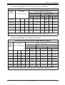
I/O Devices
SATA Connections
• SATA Ports
(from AHCI)
Two (2) I-SATA 3.0 (I-SATA 0/1)
Four (4) I-SATA 2.0 Ports (I-
SATA 2~5)
• SATA Ports
(from SCU)
Four S-SATA 2.0 Ports 0~3
(From Storage Control Unit)
• RAID Win-
dows, or Linux-
(latest kernel)
RAID 0, 1, 5, 10

1-8
X9DRH-7F/-iF/-7TF/-iTF Motherboard User’s Manual
I/O Devices
(cont.)
SAS Connections (X9DRH-7F/-7TF)
• LSI SAS 2208 Controller (w/hardware RAID support)
• SAS Ports 0~3, 4~7
• RAID Support RAID 0, 1, 5, 6, 10, 50, 60
(Hardware RAID)
IPMI 2.0
• IPMI 2.0 supported by the Novuton BMC (WPCM450)
Serial (COM) Port
• Two (2) Fast UART 16550 Connection: 9-pin RS-
232 port
VGA
• Backplane VGA Port 1
• Front Panel Accessible VGA Port 2
Peripheral
Devices
USB Devices
• Four (4) USB ports on the rear I/O panel (USB 0/1,
2/3),
• Four (4) USB connections for front access in two
headers (USB 4/5, USB 8/9),
• One (1) Type A USB connections for front access
(USB 6)
BIOS
• 16 MB AMI BIOS
®
Flash EEPROM
• APM 1.2, DMI 2.3, PCI 2.3, ACPI 1.0/2.0/3.0, USB
Keyboard, Plug & Play (PnP) and SMBIOS 2.3
Power
• ACPI/ACPM Power Management
Cong.
• Main switch override mechanism
• Keyboard Wake-up from Soft-Off
• Power-on mode for AC power recovery
• Intel
®
Intelligent Power Node Manager (NM) (Avail-
able when the NMView utility is installed in the
system)
• Manageability Engine (ME)
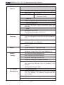
PC Health
Monitoring
CPU Monitoring
• Onboard voltage monitors for +1.8V, +3.3V, 3.3VSB,
+5V, +5V Standby, 12V, Memory, Chipset and Bat-
tery Voltage.
• CPU 5+1 -Phase switching voltage regulator
• CPU/System overheat LED and control

Chapter 1: Overview
1-9
PC Health
Monitoring
• CPU Thermal Trip support
• Thermal Monitor 2 (TM2) support
Fan Control
• Fan status monitoring with rmware 4-pin (Pulse
Width Modulation) fan speed control
• Low noise fan speed control
LED Indicators
• System/CPU Overheat LED
• Suspend-state LED
• UID/Remote UID LED
System
Management
• PECI (Platform Environment Conguration Interface)
2.0 support
• System resource alert via SuperDoctor III
• Thermal Monitor 2 (TM2) support
• SuperDoctor III, Watch Dog, NMI
• Chassis Intrusion Header and Detection
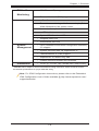
Dimensions
• 12.00" (L) x 13.00" (W) (304.80 mm x 330.20 mm)
* CPU Max TDP is subject to chassis and heatsink cooling restrictions. Please check the chassis
andheatsinkspecicationsforproperCPUTDPsizing.
Note: For IPMI Conguration Instructions, please refer to the Embedded
IPMI Conguration User's Guide available @ http://www.supermicro.com/
support/manuals/.

1-10
X9DRH-7F/-iF/-7TF/-iTF Motherboard User’s Manual
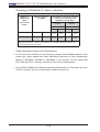
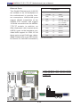
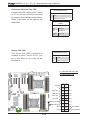
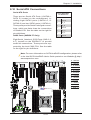
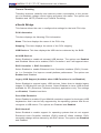
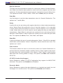
System Block Diagram
Notes: 1. This is a general block diagram and may not exactly represent
the features on your motherboard. See the Motherboard Features pages
for the actual specications of each motherboard.
2. This block diagram is intended for reference only.
#G-1
#G-2
PORTs#4~7
PORTs#0~3
800/1066/1333/1600
DDRIII
P0
#F-2
#F-1
#E-2
#E-1
DDRIII
#B-2
#B-1
#A-2
#A-1
QPI
8G
LANE6
PCI-E X8
USB 2.0
E5-2600
PCH
C602
SSB
PCI-E X8 G3
DMI2
PCI
LANE1/2/3/4
SPI
DMI2
USB
I-SATA 0/1
2 Rear
4 Front
1 Type-A
BMC
WPCM450
PCI-E X8
PCI-E X8 G3
PCI
#C-1
#C-2
PCI-E X8 G3
SAS2
8 SNB CORE
DDR-III
E5-2600
8 SNB CORE
DDR-III
QPI
8G
4GB/s
SAS
SAS
P1
P1
P0
SLOT 3
SLOT 1
SLOT 2
SLOT 5
SLOT 6
SLOT 7
SLOT 4
PCI-E X8
PCI-E X8
PCI-E X8 G3
PCI-E X8 G3
PCI-E X8 G3
DMI2#2A #1 #2A #2C #3#1 #3A #3C #2C DMI2
SAS2208
I350/X540
LAN
VGA
PCI-E X8
COM1
External
COM2
Internal
PCI-E X16
PCI-E X8
PCI-E X8
PCI-E X8 G3
PCI-E X16 G3
SCU0
SATA
#0~#3
#0~#1
#0~#6
800/1066/1333/1600
(CPU1)
(CPU2)
#D1
#D-2
#H-2
#H-1
SATA3.0
3.0 Gb/S
Group2: SATA2.0
from SCU
S-SATA0~3
SATA2.0
Group3:
SATA2.0
3.0 Gb/S
SATA2.0
I-SATA 2~5
Group1:
SATA 3.0
6.0 Gb/S
#2~#5

Chapter 1: Overview
1-11
1-2 Processor and Chipset Overview
Built upon the functionality and the capabilities of the Intel E5-2600 Series (Socket
R) processor and the C602 PCH, the X9DRH-7F/-iF/-7TF/-iTF motherboard pro-
vides the performance and feature sets required for dual_processor-based HPC/
Cluster/Database servers.
With support of Intel QuickPath interconnect (QPI) Technology, the X9DRH series
motherboard offers point-to-point serial interconnect interface with a transfer speed
of up to 8.0 GT/s, providing superb system performance.
The C602 PCH provides extensive IO support, including the following functions
and capabilities:
•PCI-Express Rev. 3.0 support
•ACPI Power Management Logic Support Rev. 3.0b or Rev. 4.0
•USB host interface backplane and front access support
•Intel Rapid Storage Technology supported
•Intel Virtualization Technology for Directed I/O (Intel VT-d) supported
•Intel Trusted Execution Technology supported
•Serial Peripheral Interface (SPI) Supported
•Digital Media Interface (DMI) supported
•Advanced Host Controller Interface (AHCI) supported

1-12
X9DRH-7F/-iF/-7TF/-iTF Motherboard User’s Manual
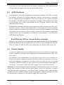
1-3 Special Features
Recovery from AC Power Loss
Basic I/O System (BIOS) provides a setting that determines how the system will
respond when AC power is lost and then restored to the system. You can choose for
the system to remain powered off (in which case you must press the power switch
to turn it back on), or for it to automatically return to the power-on state. See the
Advanced BIOS Setup section for this setting. The default setting is Last State.
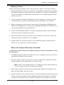
1-4 PC Health Monitoring
This section describes the features of PC health monitoring of the motherboard.
This motherboard has an onboard System_Hardware_Monitor chip that supports
PC health monitoring. An onboard voltage monitor will scan the following onboard
voltages continuously: +1.8V, 3.3V, 3.3VSB, 5V, 5VSB, +12V, Memory, Chipset and
Battery Voltage. Once a voltage becomes unstable, a warning is given, or an error
message is sent to the screen. The user can adjust the voltage thresholds to dene
the sensitivity of the voltage monitor.
Fan Status Monitor with Firmware Control
The PC health monitor chip can check the RPM status of a cooling fan. The onboard
CPU and chassis fans are controlled by IPMI Thermal Management.
Environmental Temperature Control
A thermal control sensor monitors the CPU temperature in real time and will turn
on the thermal control fan whenever the CPU temperature exceeds a user-dened
threshold. The overheat circuitry runs independently from the CPU. Once it detects
that the CPU temperature is too high, it will automatically turn on the thermal fan
control to prevent the CPU from overheating. The onboard chassis thermal circuitry
can monitor the overall system temperature and alert the user when the chassis
temperature is too high.
Note: To avoid possible system overheating, please be sure to provide
adequate airow to your system.
System Resource Alert
This feature is available when used with SuperDoctor III in the Windows OS
environment or used with SuperDoctor II in Linux. SuperDoctor is used to notify
the user of certain system events. For example, you can congure SuperDoctor
Page is loading ...
Page is loading ...
Page is loading ...
Page is loading ...
Page is loading ...
Page is loading ...
Page is loading ...
Page is loading ...
Page is loading ...
Page is loading ...
Page is loading ...
Page is loading ...
Page is loading ...
Page is loading ...
Page is loading ...
Page is loading ...
Page is loading ...
Page is loading ...
Page is loading ...
Page is loading ...
Page is loading ...
Page is loading ...
Page is loading ...
Page is loading ...
Page is loading ...
Page is loading ...
Page is loading ...
Page is loading ...
Page is loading ...
Page is loading ...
Page is loading ...
Page is loading ...
Page is loading ...
Page is loading ...
Page is loading ...
Page is loading ...
Page is loading ...
Page is loading ...
Page is loading ...
Page is loading ...
Page is loading ...
Page is loading ...
Page is loading ...
Page is loading ...
Page is loading ...
Page is loading ...
Page is loading ...
Page is loading ...
Page is loading ...
Page is loading ...
Page is loading ...
Page is loading ...
Page is loading ...
Page is loading ...
Page is loading ...
Page is loading ...
Page is loading ...
Page is loading ...
Page is loading ...
Page is loading ...
Page is loading ...
Page is loading ...
Page is loading ...
Page is loading ...
Page is loading ...
Page is loading ...
Page is loading ...
Page is loading ...
Page is loading ...
Page is loading ...
Page is loading ...
Page is loading ...
Page is loading ...
Page is loading ...
Page is loading ...
Page is loading ...
Page is loading ...
Page is loading ...
Page is loading ...
Page is loading ...
Page is loading ...
Page is loading ...
Page is loading ...
Page is loading ...
Page is loading ...
Page is loading ...
Page is loading ...
Page is loading ...
Page is loading ...
Page is loading ...
Page is loading ...
-
 1
1
-
 2
2
-
 3
3
-
 4
4
-
 5
5
-
 6
6
-
 7
7
-
 8
8
-
 9
9
-
 10
10
-
 11
11
-
 12
12
-
 13
13
-
 14
14
-
 15
15
-
 16
16
-
 17
17
-
 18
18
-
 19
19
-
 20
20
-
 21
21
-
 22
22
-
 23
23
-
 24
24
-
 25
25
-
 26
26
-
 27
27
-
 28
28
-
 29
29
-
 30
30
-
 31
31
-
 32
32
-
 33
33
-
 34
34
-
 35
35
-
 36
36
-
 37
37
-
 38
38
-
 39
39
-
 40
40
-
 41
41
-
 42
42
-
 43
43
-
 44
44
-
 45
45
-
 46
46
-
 47
47
-
 48
48
-
 49
49
-
 50
50
-
 51
51
-
 52
52
-
 53
53
-
 54
54
-
 55
55
-
 56
56
-
 57
57
-
 58
58
-
 59
59
-
 60
60
-
 61
61
-
 62
62
-
 63
63
-
 64
64
-
 65
65
-
 66
66
-
 67
67
-
 68
68
-
 69
69
-
 70
70
-
 71
71
-
 72
72
-
 73
73
-
 74
74
-
 75
75
-
 76
76
-
 77
77
-
 78
78
-
 79
79
-
 80
80
-
 81
81
-
 82
82
-
 83
83
-
 84
84
-
 85
85
-
 86
86
-
 87
87
-
 88
88
-
 89
89
-
 90
90
-
 91
91
-
 92
92
-
 93
93
-
 94
94
-
 95
95
-
 96
96
-
 97
97
-
 98
98
-
 99
99
-
 100
100
-
 101
101
-
 102
102
-
 103
103
-
 104
104
-
 105
105
-
 106
106
-
 107
107
-
 108
108
-
 109
109
-
 110
110
-
 111
111


Supermicro MBD-X9DRH-7F-O User manual
- Category
- Server/workstation motherboards
- Type
- User manual
Ask a question and I''ll find the answer in the document
Finding information in a document is now easier with AI
Related papers
-
Supermicro X9DRH-7TF User manual
-
Supermicro X9DBU-IF User manual
-
-
-
Supermicro X9DAE User manual
-
Supermicro X9DRE-TF+ User manual
-
-
-
Supermicro 5038K-i User manual
-
Supermicro X11 DP User manual
Other documents
-
Conceptronic CTC4USB3 Operating instructions
-
Equip CTC4USB3 Operating instructions
-
Gigabyte GA-7TEWH1 User manual
-
 Supero X9DRFR User manual
-
-
Sitecom CN-070 Datasheet
-
Gigabyte GS-R22T61 User manual
-
Viglen Vig430p User manual
-
MSI X299 SLI PLUS Owner's manual
-
