Page is loading ...

Parts & Maintenance
Manual
19
17
18
13
6
5
9
15
16
7
8
10
4
3
11
1 - INCLUDES ITEMS 3 - 16
GB
GA-30 Aerator
88118 – GA-30 Aerator with Steering Wheel
88119 – GA-30 Aerator with Steering Handle
4139908

Copyright 2005, Textron Inc.
“All rights reserved, including the right to reproduce this material or portions thereof in any form.”
To Order Parts
1. Write your full name and complete address on the
order.
2. Explain where and how to make shipment.
3. Give product number, name and serial number that is
stamped on the name plate or serial plate of your prod-
uct.
4. Order by the quantity desired, the part number, paint
code, and description of the part as given in the parts list.
5. Send or bring the order to an authorized Jacobsen
Dealer.
6. Inspect all shipments on receipt. If any parts are dam-
aged or missing, file a claim with the carrier before
accepting.
7. Do not return material without a letter of explanation, list-
ing the parts being returned. Transportation charges
must be prepaid.
Use of other than Jacobsen authorized parts will void the warranty.
This manual is designed for the Maintenance and Adjustment of this equipment.
Use the maintenance and adjustment instructions included in this manual and the operating
instructions included in the Safety and Operation Manual to service the machine.
The Safety and Operation Manual must be kept in the pouch on the back of the seat at all times
for reference by the operator.
1 Safety
1.1 Operating Safety............................................... 4
1.2 Important Safety Notes .....................................5
2 Specifications
2.1 Product Identification ........................................ 6
2.2 Kohler CH 18 S Engine .....................................6
2.3 aerator ..............................................................6
2.4 Weights and Dimensions ..................................7
2.5 Accessories & Support Literature ..................... 7
3 Set-Up
3.1 Set-Up............................................................... 8
4 Adjustments
4.1 General ............................................................. 9
4.2 Drive Belt Adjustment .......................................9
4.3 Brake Adjustment ............................................. 9
4.4 Hydrostat Pedal and Linkage Adjustment .......10
4.5 Steering Wheel Installation and Adjustment ...10
4.6 Spacing Control Adjustment ...........................11
4.7 Reversing Gearbox Proper Gear Backlash ....11
4.8 Reversing Gear Box Adjustment ....................12
4.9 Torque Specification .......................................13
5 Maintenance
5.1 General ........................................................... 14
5.2 Engine .............................................................14
5.3 Engine Oil .......................................................14
5.4 Fuel .................................................................15
5.5 Fuel System ....................................................15
5.6 Battery ............................................................15
5.7 Jump Starting ..................................................16
5.8 Charging Battery .............................................16
5.9 Hydraulic Hoses ..............................................16
5.10 Hydraulic Oil and Filter ...................................17
5.11 Electrical System ............................................17
5.12 Muffler and Exhaust ........................................ 18
5.13 Aerator Head .................................................. 18
5.14 Sealed chain maintenance ............................. 18
5.15 Windrow Attachment (Accessory) .................. 18
5.16 Motor Drive Sprocket ...................................... 18
5.17 Tires ................................................................ 19
5.18 Wheel Mounting Procedure ............................ 19
5.19 Care and Cleaning .......................................... 19
5.20 Storage ........................................................... 20
6 Troubleshooting
6.1 General Troubleshooting ................................ 21
6.2 Drive Belt (Breaking) ...................................... 22
6.3 Leaving Cores in the Turf ............................... 22
6.4 Return Link Hitting Reversing Gear Box ......... 23
6.5 Unit Will Not Move .......................................... 24
6.6 System Noisy .................................................. 24
6.7 Sluggish Acceleration or Deceleration ............ 24
6.8 Hydraulic Oil Hot ............................................. 24
6.9 Correction of Tufting Problem ......................... 25
6.10 Hole Spacing Inconsistent .............................. 25
6.11 Engine Will Not Start ...................................... 25
6.12 Aerator Ram Timing for Reduced Tufting ....... 25
6.13 Timing For Smoother Ride (Fairway Aeration) 26
6.14 Timing For Reduced Tufting (Green Aeration) 27
7 Maintenance & Lubrication Charts
7.1 General........................................................... 28
7.2 Lubrication Chart ............................................ 28
7.3 Maintenance Charts ....................................... 29
8Notes
9 Parts Catalog
9.1 Table Of Contents .......................................... 31
Litho in U.S.A. 11-2005

3
Suggested Stocking Guide
To Keep your Equipment fully operational and productive, maintain a stock of the more commonly used maintenance
items. We have included part numbers for additional support materials and training aids. A more complete listing of
accessories and attachments can be found in the Specifications Section.
How To Use This Manual
Abbreviations
N/S - Not serviced seperately, can only be obtained by ordering main component or kit.
AR -Variable quantity or measurement is required to obtain correct adjustment.
Symbols such as ▲, next to the item number, indicate that a note exists which contain additional information
important in ordering that part.
Indented Items
Bulleted items indicate component parts that are included as part of an assembly or another component. These parts
can be ordered separetely or as part of the main component.
Item Part No. Qty Description Serial Numbers/Notes
▲ 1 123456 1 Mount, Valve Indicates a piece part
2 789012 1 Valve, Lift Includes Items 2 and 3
3 345678 1 • Handle Serviced part included with Item 2
4 N/S 1 • Seal Kit Non serviced part included with Item 2
5 901234.6 1 Screw, 1/4-20 x 2” Hex Head Indicates part 901234 painted Orange
5 901234.2 1 Screw, 1/4-20 x 2” Hex Head Indicates part 901234 painted Green
Service Parts
Qty. Part No. Description Qty. Part No. Description
842502 Engine Oil Filter 522887 Drive Belt
842509 Engine Air Filter 842517 Spark Plug
842504 Engine Fuel Filter
522972 Hydraulic Oil Filter
842513 Air Filter Pre Cleaner
4139909 Safety and Operation Manual 4139908 Parts and Maintenance Manual
Paint Codes
A paint code suffix is required when ordering painted
parts. The available paint codes for each part are listed in
the Parts Catalog using the following format:
[Part Number].[Paint Code]
For example:
123456.7 represents part 123456 painted Gloss Black.
If more than one paint code is listed, choose the paint
code that matches your machine.
Parts listed in the Parts Catalog without a paint code
suffix do not need the suffix added to order parts.
The following is a list of Jacobsen Paint Code Suffixes
.2 Green
.6 Orange
.7 Gloss Black
.8 High Heat Flat Black
.9 Flat Black
.10 White
.11 Non Skid Gray
.20 Red

1 SAFETY
4
1 SAFETY
1.1 OPERATING SAFETY ______________________________________________________
1. Safety is dependent upon the awareness, concern
and prudence of those who operate or service the
equipment. Never allow minors to operate any
equipment.
2. It is your responsibility to read this manual and all
publications associated with this equipment (Safety
and Operation Manual, engine manual, accessories
and attachments). If the operator can not read
English it is the owner’s responsibility to explain the
material contained in this manual to them.
3. Learn the proper use of the machine, the location
and purpose of all the controls and gauges before
you operate the equipment. Working with unfamiliar
equipment can lead to accidents.
4. Never allow anyone to operate or service the
machine or its attachments without proper training
and instructions; or while under the influence of
alcohol or drugs.
5. Wear all the necessary protective clothing and
personal safety devices to protect your head, eyes,
ears hands and feet. Operate the machine only in
daylight or in good artificial light.
6. Inspect the area where the equipment will be used.
Pick up all the debris you can find before operating.
Beware of overhead obstructions (low tree limbs,
electrical wires, etc.) and also underground
obstacles (sprinklers, pipes, tree roots, etc.) Enter a
new area cautiously. Stay alert for hidden hazards.
7. Never direct discharge of material toward
bystanders, nor allow anyone near the machine
while in operation. The owner/operator can prevent
and is responsible for injuries inflicted to
themselves, to bystanders and damage to property.
8. Never operate equipment that is not in perfect
working order or is without decals, guards, shields,
discharge deflectors or other protective devices
securely fastened in place.
9. Never disconnect or bypass any switch.
10. Carbon monoxide in the exhaust fumes can be fatal
when inhaled. Never operate the engine without
proper ventilation.
11. Fuel is highly flammable, handle with care.
12. Keep the engine clean. Allow the engine to cool
before storing and always remove the ignition key.
13. Disengage all drives and engage parking brake
before starting the engine (motor). Start the engine
only when sitting in operator’s seat, never while
standing beside the unit.
14. Equipment must comply with the latest federal,
state, and local requirements when driven or
transported on public roads.
15. Never use your hands to search for oil leaks.
Hydraulic fluid under pressure can penetrate the
skin and cause serious injury.
16. Operate the machine up and down the face of the
slopes (vertically), not across the face (horizontally).
17. To prevent tipping or loss of control, do not start or
stop suddenly; reduce speed when making sharp
turns. Use caution when changing direction on
slopes.
18. Keep legs, arms and body inside the seating
compartment while the vehicle is in motion.
This machine is to be operated and maintained as specified in this manual and is intended for the professional
maintenance of specialized turf grasses. It is not intended for use on rough terrain or long grasses.
WARNING
EQUIPMENT OPERATED IMPROPERLY OR BY UNTRAINED PERSONNEL CAN BE DANGEROUS.
Familiarize yourself with the location and proper use of all controls. Inexperienced operator’s should receive
instruction from someone familiar with the equipment before being allowed to operate the machine.
!

SAFETY 1
5
1.2 IMPORTANT SAFETY NOTES ________________________________________________
This safety alert symbol is used to alert you to potential hazards.
DANGER - Indicates an imminently hazardous situation which, if not avoided, WILL result in death or serious injury.
WARNING - Indicates a potentially hazardous situation which, if not avoided, COULD result in death or serious
injury.
CAUTION - Indicates a potentially hazardous situation which, if not avoided, MAY result in minor or moderate injury
and property damage. It may also be used to alert against unsafe practices.
For pictorial clarity, some illustrations in this manual may show shields, guards or plates open or removed. Under no
circumstances should this equipment be operated without these devices securely fastened in place
By following all instructions in this manual, you will prolong the life of your machine and maintain its maximum
efficiency. Adjustments and maintenance should always be performed by a qualified technician.
If additional information or service is needed, contact your Authorized Jacobsen Dealer who is kept informed of the
latest methods to service this equipment and can provide prompt and efficient service.
Use of other than original or authorized Jacobsen parts and accessories will void the warranty.
WARNING
The interlock system on this aerator prevents the engine from starting unless
the brake lever is engaged, aerator switch is off and traction pedal is in
neutral. The system will stop the engine if the operator leaves the seat with
the aerator head lowered, parking brake disengaged or traction pedal out of
neutral.
NEVER operate Aerator unless the Interlock System is working
WARNING
1. Before leaving the operator’s position for any reason:
a. Return traction pedal to neutral
b. Raise aerator head
c. Engage parking brake.
d. Stop engine.
2. Keep hands, feet, and clothing away from moving parts. Wait for all
movement to stop before you clean, adjust or service the machine.
3. Keep the area of operation clear of all bystanders and pets.
4. Never carry passengers, unless a seat is provided for them.
5. Never operate aerating equipment without the discharge deflector
securely fastened in place.
!
!
!

2 SPECIFICATIONS
6
2 SPECIFICATIONS
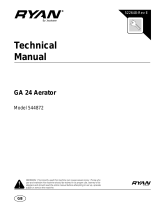
2.1 PRODUCT IDENTIFICATION_________________________________________________
88118............................ GA-30 Aerator with Steering
Wheel.
88119............................ GA-30 Aerator with Steering
Handle.
Serial Number .............. An identification plate, like the
one shown, listing the serial
number, is attached to the right
side of the aerator head frame.
Always provide the serial number of the unit when
ordering replacement parts or requesting service
information.
2.2 KOHLER CH 18 S ENGINE __________________________________________________
Make............................. Kohler
Model............................ CH18S
Horsepower .................. 18 hp (13.4 kW) @3600 rpm
Note: Actual sustained horsepower will likely be lower
than listed in specifications due to operating limitations
and environmental factors
Displacement................ 38.1 cu. In. (624 cc)
Torque .......................... 54 ft. lbs. (73 Nm) @ 2200 rpm
Fuel:
Type........................ Unleaded Gasoline
Rating ..................... 87 Octane Minimum
Capacity.................. 6.25 U.S. Gal. (23.8 liters)
High speed - rpm...........3150 no load
Low Idle - rpm................1750 no load
Lubrication:
Capacity...................2.1 qt (2 liters)
Type.........................SAE 10W30
API Classification ....SG, SH, SJ
Air Filter .........................Replaceable paper element with
oiled pre-cleaner.
Alternator.......................40 amp
Cooling System .............Air Cooled
2.3 AERATOR________________________________________________________________
Tires
Front ....................... 18-9.50 x 8 4 ply
Rear ........................ 18-10.50 x 8 4 ply
Pressure: ...................... 12 psi (83 kPa)
Battery:
Type........................ 12 Volt Lead/Acid
Group...................... 45 GMF
Parking Brake ............... Mechanical front wheel disk
Speed:
Aeration (2 WD).......up to 28,125 sq ft/hr
Hydraulic System:
Capacity ........................8 U.S. gal. (30.28 liters) System
Fluid Type......................GreensCare 68
Return Filter...................Full Flow 10 micron
Steering ........................Hydrostatic power steering
Tine Lift..........................Hydraulic Double Acting
Cylinders
Product
EEC Sound
Power
Sound
Pressure Level
Operator Ear
Vibration M/S
2
Arms Body
88118
88119
<105 dba
<105 dba
90 dba
90 dba
3.7
3.7
0.11
0.11
MODEL
SERIAL NUMBER
MANUFACTURING CODE
JACOBSEN
1721 Packard Avenue
Racine Wisconsin 53403-2564
GA-30
544915
1601

SPECIFICATIONS 2
7
2.4 WEIGHTS AND DIMENSIONS ________________________________________________
Dimensions: Inches (m)
Length ......................................................... 77.6 (2)
Length - With Window Attachment ............ 107.6 (2.7)
Height .......................................................... 53.3 (1.4)
Wheel Base.................................................. 59.1 (1.5)
Width .............................................................. 60 (1.5)
Turning Radius................................................ 18 (0.5)
Weights: Lbs. (kg)
Working Weight Less Operator
88119.......................................................... 1402 (636)
88118.......................................................... 1402 (636)
2.5 ACCESSORIES & SUPPORT LITERATURE _____________________________________
Contact your area Jacobsen Dealer for a complete listing of accessories and attachments.
Accessories
Orange Paint (16 oz. spray) ................................2700345
Orange Paint (1 qt. can)......................................2700351
Windrow ..............................................................4116980
Support Literature
Safety & Operation Manual.................................4138809
Parts & Maintenance Manual..............................4138808
Video, operator ...................................................4128273
CAUTION
Use of other than Jacobsen authorized parts and accessories may cause personal injury or damage to the
equipment and will void the warranty
!

3 SET-UP
8
3 SET-UP
3.1 SET-UP __________________________________________________________________
Loose parts kit includes additional tines.
1. Remove carton from unit.
2. Lift seat assembly (lever located below seat on
right–front side, Figure 3A), cut ties from wooden
block located on hydraulic cylinder and remove
block.
Figure 3A
A. Cover latch
3. Insert three (3) tines per holder and tighten screws
securely. BE SURE tines are tight against shoulder
of tine holder.
4. Attach tine holders to tine rams and secure with two
(2) flangelock nuts (See Figure 3B).
5. Remove screw from beneath aerator lift pedal.
Figure 3B
A. Flangelock Nut
B. Tine Holder
C. Tine
Note: To prevent corrosion on gauge stem, replace fuel
tank cap with gauge cap after two (2) full tanks of fuel
have been run through the system.
On models shipped with a plastic bag over gauge stem,
fill fuel tank and remove bag before installing into fuel
tank.
WARNING
To prevent possible injury to yourself or others, stay
clear when cutting banding. Banding is under tension
and can snap back when cut.
DO NOT operate this equipment until you have read
the controls and operating sections thoroughly!
!
A
FRONT
OF
UNIT
C
A
B

ADJUSTMENTS 4
9
4 ADJUSTMENTS
4.1 GENERAL ________________________________________________________________
1. Adjustments and maintenance should always be
performed by a qualified technician. If proper
adjustment cannot be made, contact an authorized
Jacobsen Dealer.
2. Replace, do not adjust, worn or damaged
components.
3. Long hair, jewelry or loose fitting clothing may get
tangled in moving parts.
4. Do not change governor settings or overspeed the
engine
4.2 DRIVE BELT ADJUSTMENT _________________________________________________
Inspect and adjust new belt after first 50 hours of
operation. Check and adjust annually thereafter.
1. Position the driven belt pulley (Part No. 522890) 1/8”
- 3/16” (3.5 - 4.8 mm) away from the aerator frame.
2. Adjust the driver pulley (Part No. 521680) to align
with the driven pulley within 1/16” (1.6 mm).
3. Adjust all belt guides to within 1/16” - 3/16” (1.6 -
3.5 mm) of gap from belt.
4. The belt stop (Part No. 547547) should be
positioned below the belt.
5. A 1/8” - 3/16” (3.5 - 4.8 mm) gap must be left
between the threaded ends of the belt guide and all
return linkage.
6. Check to make sure the head mechanism fully
disengages when head is in the raised position.
4.3 BRAKE ADJUSTMENT______________________________________________________
1. Position the brake cam (Part No. 540039) so the
brake buttons (Part No. 523203) are located in the
bottom of the cam groove surface.
2. Locate the 3/8 - 16 centerlock nut (Part No. 800292)
at the caliper pivot point. This nut is used to retain
the calipers but must have clearance to allow
pivoting action. Adjust the nut to 1/16 turn short of
being tight.
3. Adjust the brake rod (Part No. 523202) and clevis
(Part No. 827498) with the return spring (Part No.
817613) installed, to the correct length which will
allow the bellcrank to be connected to the rotary
cam.
4. Adjust the caliper by using the two (2) 1/2 - 13 nuts
(Part No. 548051) until the calipers allow the 38
tooth sprocket (Part No. 522856) on the differential
to rotate freely.
5. Adjust the calipers to allow 1/2” ± 1/8” (13 mm ± 3.5
mm) of brake pedal travel before the calipers
engage firmly against the sprocket. Secure the two
(2) 1/2 - 13 nuts to maintain the adjustment.
6. Check to make sure brakes work properly when
applied.
WARNING
To prevent injury, lower implements to the ground,
disengage all drives, engage parking brake, stop
engine and remove key from ignition switch before
making any adjustments or performing maintenance.
Make sure the aerator is parked on a solid and level
surface. Never work on a aerator that is supported
only by the jack. Always use jack stands.
If only the front or rear of the aerator is raised, place
chocks in front of and behind the wheels that are not
raised.
!
CAUTION
Be careful to prevent entrapment of the hands and
fingers between moving and fixed components of the
machine.
!

4 ADJUSTMENTS
10
4.4 HYDROSTAT PEDAL AND LINKAGE ADJUSTMENT _____________________________
1. Locate the hydrostat pump arm (Part No. 547680) at
the rear of the machine and against the internal stop
of the pump.
2. Move the pump arm off the internal pump stop with
the pump arm stop bracket (Part No. 523410)
approximately 1/32” (.8 mm).
3. Connect the control link (Part No. 523419) with the
bellcrank (Part No. 547738) in the “Neutral” position.
4. Adjust the rod (Part No. 523419) so there is no
hydraulic fluid output to the drive motor.
5. Install the control rod (Part No. 523115) with the
foot pedal (Part No. 547614) in a “Forward” position
or a maximum of 1/16” (1.6 mm) off the floor pan.
The hydrostat pump arm (Part No. 547680) should
be against the stop bracket (Part No. 523410),
toward the rear of the machine.
4.5 STEERING WHEEL INSTALLATION AND ADJUSTMENT _________________________
For model 88118
1. Install fork spindle bearings and fork.
2. Assemble steering box supports. Mounting bolts
should be finger tight and still allow movement of
brackets.
3. Install key (Part No. 551041) in spindle.
4. Assemble lower housing assembly (Part No.
880552) and idler adjustment bolt (Part No.
816452). Place one (1) spacing washer (Part No.
816446) over hole on inside of casting and insert
adjustment bolt. Place one (1) locating washer
(Part No. 816449) over adjusting bolt with knurled
side against outside of lower casting. Tighten nut
(Part No. 800612) to finger tight.
5. Attach above assembly to steering box supports.
Tighten mounting bolts to finger tight.
6. Place liberal amount of lubricant in recess on idler
adjusting bolt and place cluster gear idler (Part No.
830168) over adjusting bolt.
7. Install steering gear on spindle (Part No. 830167).
Apply Loctite #271 sealant to the spindle shaft
threads before installing fork spindle nut (Part No.
825672). Hold fork, tighten fork spindle nut (Part No.
825672) tight and torque to 60 - 70 ft.-lbs. (81 - 95
N-m). Apply a liberal amount of lithium base grease
lubricant to gear teeth and all bearing surfaces.
8. Block up wheel and adjust height of the lower
housing so that when fork is held against thrust
washer there is 1/64” - 1/16” (.4 mm - 1.6 mm)
clearance between top of cluster gear teeth and
bottom of steering gear teeth. Tighten three (3)
support mounting bolts. Move entire wheel
assembly up and down to ensure that there is not
more than 1/16” (1.6 mm) end play or spindle will
interfere with steering case.
9. Place one (1) spacing washer (Part No. 816446)
over idler adjustment bolt. Assemble upper housing
assembly to lower housing assembly. Place one (1)
locating washer (Part No. 816449) over adjusting
bolt with knurled side against casting and tighten nut
(Part No. 800612) to finger tight. Tighten the
housing attaching bolts and torque equally 3 - 4 ft.-
lbs. (4 - 5 N-m).
10. Rotate front fork side to side to check gear
alignment. If a smooth, free turning fork is not
achieved, loosen top three (3) mounting bolts of
support brackets and adjust housing assembly until
a smooth turning fork is acquired. Tighten bolts
and recheck turn of fork.
11. Further adjustment is allowed by loosening bottom
two (2) mounting bolts; however, when this
adjustment is required, it may be necessary to
remove top housing assembly and reset the 1/64” -
1/16” max. (.4 - 1.6 mm max.) dimension between
the idler gear and driven gear.
12. After completion of the above steps, torque the
following equally in sequence:
a. 1/4 - 20 assembly bolts 8 - 10 ft.-lbs.
(11 - 18 N-m)
b. 3/8 - 18 upper three (3) and lower two (2)
mounting bolts 20 - 25 ft.-lbs. (27 - 34 N-m).
13. To adjust backlash or hold front wheel. Check to
see that the fork does not turn. Loosen top and
bottom idler adjusting nuts and turn the steering
wheel counterclockwise and hold with light pressure.
Snug the bottom idler adjusting nut and then the top
adjusting nut.
Note: Care must be taken to prevent cocking the idler
shaft.
14. With slight pressure on the steering wheel in
counterclockwise direction, tighten bottom nut to 40
- 50 ft.-lbs. (54 - 68 N-m). Check backlash for a
maximum of 1/4” (6.4 mm) travel of the steering
wheel, then tighten top adjusting nut to 40 - 50 ft.-

ADJUSTMENTS 4
11
lbs. (54 - 68 N-m). Check operation of the steering
for free operation. A slight amount of roughness is
permitted after the front wheel has turned either
direction 15°. It is better to have the allowable
roughness than the maximum permitted backlash.
If it is necessary to readjust the idler shaft, the
locating washers (Part No. 816449) must be rotated
to prevent the serrations from falling into the same
marks.
4.6 SPACING CONTROL ADJUSTMENT __________________________________________
Note: Hole spacing on the GA-30 is controlled by the
forward speed of the unit. The faster the unit travels, the
more space between the holes.
1. Make a test run with the spacing control knob set at 2
1/2” (64 mm), and direction control pedal fully
depressed.
2. Measure the distance (center to center) between the
holes. If the distance is more or less than 2 1/2” (64
mm) adjust as follows:
Set the spacing control lever at the 2 1/2” (64 mm)
mark.
3. Jack rear wheels off the ground. Support unit with
jack stands.
4. Remove bolt from chain drive sprocket.
5. Lift seat and remove internal rubber cover.
6. Remove side panel and muffler cover, remove drive
belt.
7. With the aerator head fully lowered, and the throttle
at full speed (3600 ± 75 R.P.M.), place a slow
speed tachometer against the threaded center of
the hydraulic motor.
8. Adjust the spacing control rod (Part No. 524160)
until the hydraulic motor speed stabilizes at 28 ± 1
R.P.M. Use the adjusting screw (Part No. 524453)
to set position by screwing forward to decrease hole
spacing (lengthening rod). Screw backward (shorten
rod) to increase hole spacing. Lock the two (2) nuts
(Part No. 306320) and override spring (Part No.
524083) into position so that the spring may
compress 1/8” (3.2 mm) after adjustment is
complete. Refer to Figure 4A.
9. Replace drive belt and panels.
10. Replace internal rubber cover and chain drive
sprocket bolt.
Figure 4A
A. Nuts
B. Override spring
C. Spacing Control rod
D. Adjusting screw
4.7 REVERSING GEARBOX PROPER GEAR BACKLASH ____________________________
Note: The gear lash can be inspected while the reversing
gearbox is still on the unit. The gear backlash should be
zero.
1. Locate 2 tine rams connected through linkage to the
same reversing gearbox. Grasp both of the tine rams
low near the tine holder mounting. Push one of the
tine rams in until it stops and hold it there. Slowly
move the other tine ram in and out, look for
independent movement of the tine ram and listen for
a knocking noise coming from the gears in the
reversing gearbox.
2. A correctly adjusted reversing gearbox should feel
solid and the tine rams should not move indepen-
dently from one another. There should not be any
knocking noises coming from the gears in the
reversing gearbox. If the tine ram does move
independently from the other tine ram, the linkage
from the tine ram to the reversing gearbox should
be inspected for damage or wear. If no wear or
damage is found in the linkage, then the reversing
gearbox should be adjusted for zero gear backlash.
C
D
A
B

4 ADJUSTMENTS
12
4.8 REVERSING GEAR BOX ADJUSTMENT _______________________________________
Note: The reversing box is heavy BE SURE it is not
dropped while being removed from the GA-30.
1. Unscrew plugs from gearbox halves and turn
gearbox upside down in a drain pan to drain gear oil
before disassembly. Later units are filled with
grease.
2. Once gearbox has drained, loosen and remove four
(4) 3/8” screws, lockwashers and locknuts securing
gearbox halves.
3. Separate gearbox halves and remove gasket. Clean
and rinse out the grease from the gearbox halves.
4. Prepare case half surfaces for installation of new
gasket.
5. Using a new gasket, place both halves upside down
on a flat surface and carefully engage the gears so
both vertical links are pointing straight up and are
facing forward when the gearbox halves are placed
together.
6. Loosely bolt the gearbox halves together using the
original hardware, making sure the lockwashers are
against the screw heads.
7. With the gearbox still upside down on a flat surface,
laterally slide the halves together to get a zero
backlash on the gears (when both links are pointing
upward). Tighten the four (4) 3/8 - 24 x 1 1/4”
screws to secure the gearbox halves together and
torque to 35 ± 5 ft.-lbs. (47 ± 7 N-m). Refer to
Figure 4B.
8. Fill gearbox with grease by pumping into one
gearbox plug hole and filling until it comes out the
other hole.
Figure 4B
A. Gear box halves
A

ADJUSTMENTS 4
13
4.9 TORQUE SPECIFICATION___________________________________________________
Jacobsen uses Grade 5 bolts as standard, unless otherwise noted.
CAUTION
All torque values included in these charts are approximate and are for reference only. Use of these torque values is
at your sole risk. Jacobsen is not responsible for any loss, claim, or damage arising from the use of these charts.
Extreme caution should always be used when using any torque value.
AMERICAN NATIONAL STANDARD FASTENERS
SIZE UNITS GRADE 5 GRADE 8
#6-32 in-lbs (Nm) 20 (2.3) –
#8-32 in-lbs (Nm) 24 (2.7) 30 (3.4)
#10-24 in-lbs (Nm) 35 (4.0) 45 (5.1)
#10-32 in-lbs (Nm) 40 (4.5) 50 (5.7)
#12-24 in-lbs (Nm) 50 (5.7) 65 (7.3)
1/4-20 in-lbs (Nm) 95 (10.7) 125 (14.1)
1/4-28 in-lbs (Nm) 95 (10.7) 150 (17.0)
5/16-18 in-lbs (Nm) 200 (22.6) 270 (30.5)
5/16-24 in-lbs (Nm) 240 (27.1) 300 (33.9)
3/8-16 ft-lbs (Nm) 30 (40.7) 40 (54.2)
3/8-24 ft-lbs (Nm) 35 (47.5) 45 (61.0)
7/16-14 ft-lbs (Nm) 50 (67.8) 65 (88.1)
7/16-20 ft-lbs (Nm) 55 (74.6) 70 (94.9)
1/2-13 ft-lbs (Nm) 75 (101.7) 100 (135.6)
1/2-20 ft-lbs (Nm) 85 (115.3) 110 (149.2)
9/16-12 ft-lbs (Nm) 105 (142.4) 135 (183.1)
9/16-18 ft-lbs (Nm) 115 (155.9) 150 (203.4)
5/8-11 ft-lbs (Nm) 150 (203.4) 195 (264.4)
5/8-18 ft-lbs (Nm) 160 (217.0) 210 (284.8)
3/4-10 ft-lbs (Nm) 170 (230.5) 220 (298.3)
3/4-16 ft-lbs (Nm) 175 (237.3) 225 (305.1)
7/8-14 ft-lbs (Nm) 300 (406.8) 400 (542.4)
AMERICAN NATIONAL STANDARD FASTENERS
SIZE UNITS GRADE 5 GRADE 8
METRIC FASTENERS
SIZE UNITS
Non Critical
Fasteners into
Aluminum
M4 Nm (in-lbs) 1.2 (11) 1.7 (15) 2.9 (26) 4.1 (36) 5.0 (44) 2.0 (18)
M5 Nm (in-lbs) 2.5 (22) 3.2 (28) 5.8 (51) 8.1 (72) 9.7 (86) 4.0 (35)
M6 Nm (in-lbs) 4.3 (38) 5.7 (50) 9.9 (88) 14.0 (124) 16.5 (146) 6.8 (60)
M8 Nm (in-lbs) 10.5 (93) 13.6 (120) 24.4 (216) 33.9 (300) 40.7 (360) 17.0 (150)
M10 Nm (ft-lbs) 21.7 (16) 27.1 (20) 47.5 (35) 66.4 (49) 81.4 (60) 33.9 (25)
M12 Nm (ft-lbs) 36.6 (27) 47.5 (35) 82.7 (61) 116.6 (86) 139.7 (103) 61.0 (45)
M14 Nm (ft-lbs) 58.3 (43) 76.4 (55) 131.5 (97) 184.4 (136) 219.7 (162) 94.9 (70)
4.8 5.8 8.8 10.9 12.9

5 MAINTENANCE
14
5 MAINTENANC E
5.1 GENERAL________________________________________________________________
1. Adjustment and maintenance should always be
performed by a qualified technician. If proper
adjustments cannot be made, contact an Authorized
Jacobsen Dealer.
2. Inspect the equipment on a regular basis, establish
a maintenance schedule and keep detailed records.
a. Keep the equipment clean.
b. Keep all moving parts properly adjusted and
lubricated.
c. Replace worn or damaged parts before operating
the machine.
d. Keep all fluids at their proper levels.
e. Keep shields in place and all hardware securely
fastened.
f. Keep tires properly inflated.
3. Long hair, jewelry or loose fitting clothing may get
tangled in moving parts.
4. Use the illustrations in the Parts Catalog as
reference for the disassembly and reassembly of
components.
5. Recycle or dispose of all hazardous materials
(batteries, fuel, lubricants, anti-freeze, etc.)
according to local, state or federal regulations.
5.2 ENGINE _________________________________________________________________
Important: A separate Engine Manual, prepared by
the engine manufacturer, is supplied with this unit.
Read the engine manual carefully until you are
familiar with the operation and maintenance of the
engine. Proper attention to the engine
manufacturer’s directions will assure maximum
service life of the engine. To order replacement
engine manuals contact the engine manufacturer.
The proper break-in of a new engine can make a
considerable difference to the performance and life of the
engine.
During the break-in period, Jacobsen recommends the
following:
1. During the first 50 hours of operation, a new engine
should be allowed to reach an operating temperature
of at least 140°F (60°C) prior to operation at full load.
2. Check the engine oil level twice daily during the first
50 hours of operation. Higher than normal oil
consumption is not uncommon during the initial
break-in period.
3. Change engine oil and oil filter element after first 50
hours of operation.
4. Refer to Section 7.3 and Engine Manual for specific
maintenance intervals.
5.3 ENGINE OIL ______________________________________________________________
Check the engine oil at the start of each day, before
starting the engine. If the oil level is low, remove oil filler
cap and add oil as required.
Perform initial oil change after first 50 hours of operation
and every 100 hours thereafter. See Engine Manual.
Use only engine oils with API classification SG, SH, or
SJ.
WARNING
Before you clean, adjust, or repair this equipment,
disengage all drives, lower implements to the ground,
stop engine and remove key from ignition switch to
prevent injuries
!

MAINTENANCE 5
15
5.4 FUEL ____________________________________________________________________
Handle fuel with care - it is highly flammable. Use an
approved container, the spout must fit inside the fuel filler
neck. Avoid using cans and funnels to transfer fuel.
• Fill the fuel tank to full mark on fuel gauge.
• Store fuel according to local, state or federal ordi-
nances and recommendations from your fuel sup-
plier.
• Never overfill or allow the tank to become empty.
• Check fuel lines and clamps every 50 hours.
Replace fuel lines and clamps at the first sign of
damage.
• Use clean, fresh, unleaded gasoline, 87 octane
minimum. Refer to Engine Manual for additional
information.
5.5 FUEL SYSTEM ____________________________________________________________
Refer to Section 7.3 for specific maintenance intervals. Before replacing any filter, thoroughly clean the filter
housing and the area around the filter. Dirt must not be
allowed to enter into fuel system.
5.6 BATTERY ________________________________________________________________
Make absolutely certain the ignition switch is “Off” and
the key has been removed before servicing the battery.
Tighten cables securely to battery terminals and apply a
light coat of silicone dielectric grease to terminals and
cable ends to prevent corrosion. Keep vent caps and
terminal covers in place
Check the electrolyte level every 100 hours. Keep the
cable ends, battery and battery posts clean.
Verify battery polarity before connecting or disconnecting
the battery cables.
1. When installing the battery, always assemble the
RED, positive (+) battery cable first and the ground,
BLACK, negative (-) cable last.
2. When removing the battery, always remove the
ground, BLACK, negative (-) cable first and the
RED, positive (+) cable last.
Make sure battery is properly installed and secured to the
battery tray
WARNING
Never remove the fuel cap from the fuel tank, or add
fuel, when the engine is running or while the engine is
hot.
Do not smoke when handling fuel. Never fill or drain
the fuel tank indoors.
Do not spill fuel and clean spilled fuel immediately.
Never handle or store fuel containers near an open
flame or any device that may create sparks and ignite
the fuel or fuel vapors.
Be sure to reinstall and tighten fuel cap securely.
!
CAUTION
Always use insulated tools, wear protective glasses or
goggles and protective clothing when working with
batteries. You must read and obey all battery
manufacturer’s instructions.
!
WARNING
Battery posts, terminals and related accessories
contain lead and lead compounds, chemicals known
to the State of California to cause cancer and
reproductive harm. Wash your hands after
handling.
!

5 MAINTENANCE
16
5.7 JUMP STARTING __________________________________________________________
Before attempting to “jump start” the aerator, check the
condition of the discharged battery, see Section 5.6
When connecting jumper cables:
1. Stop the engine on the vehicle with a good battery.
2. Connect RED jumper cable to the positive (+)
terminal on the good battery and to the positive (+)
terminal on the “discharged” battery.
3. Connect the BLACK jumper cable from the negative
(-) terminal on the good battery to the frame of the
aerator with the discharged battery.
After cables have been connected, start the engine on
the vehicle with the good battery then start the aerator.
5.8 CHARGING BATTERY _____________________________________________________
1. Refer to Section 5.6. Read the Battery and Charger’s
manual for specific instructions.
2. Whenever possible, remove the battery from the
aerator before charging. If battery is not sealed,
check that the electrolyte covers the plates in all the
cells.
3. Make sure the charger is “Off”. Then connect the
charger to the battery terminals as specified in the
charger’s manual.
4. Always turn the charger “Off” before disconnecting
charger from the battery terminals.
5.9 HYDRAULIC HOSES _______________________________________________________
1. Always lower implements to ground, disengage all
drives, engage parking brake, stop engine and
remove key before inspecting or disconnecting
hydraulic lines or hoses.
2. Check visible hoses and tubes daily. Look for wet
hoses or oil spots. Replace worn or damaged hoses
and tubes before operating the machine.
3. The replacement tube or hoses must be routed in
the same path as the existing hose, do not move
clamps, brackets and ties to a new location.
4. Thoroughly inspect all tubes, hoses and connections
every 250 hours.
Important: The hydraulic system can be permanently
damaged if the oil becomes contaminated. Before
disconnecting any hydraulic component, clean the
area around the fittings and the hose ends to keep
impurities out of the system.
a. Before disconnecting any hydraulic component,
tag or mark the location of each hose then clean
the area around the fittings.
b. As you disconnect the component, be prepared
to assemble plugs or caps to the hose ends and
open ports. This will keep impurities out of the
hydraulic system and also prevent oil spills.
c. Make sure “O” rings are clean and hose fittings
are properly seated before tightening.
WARNING
Batteries generate explosive hydrogen gas. To
reduce the chance of an explosion, avoid creating
sparks near battery. Always connect the negative
jumper cable to the frame of the aerator with the
discharged battery, away from the battery.
!
WARNING
Charge battery in a well ventilated area. Batteries
generate explosive gases. To prevent an explosion,
keep any device that may create sparks or flames
away from the battery.
To prevent injury, stand away from battery when the
charger is turned on. A damaged battery could
explode.
!
WARNING
To prevent serious injury from hot, high pressure oil,
never use your hands to check for oil leaks, use paper
or cardboard.
Hydraulic fluid escaping under pressure can have
sufficient force to penetrate skin. If fluid is injected into
the skin it must be surgically removed within a few
hours by a doctor familiar with this form of injury or
gangrene may result.
!

MAINTENANCE 5
17
d. Keep the hose from twisting. Twisted hoses can
cause couplers to loosen as the hose flexes
during operation resulting in oil leaks.
e. Kinked or twisted hoses can restrict the oil flow
causing the system to malfunction and the oil to
overheat and also lead to hose failure.
5.10 HYDRAULIC OIL AND FILTER _______________________________________________
Refer to Section 7.3 for specific maintenance intervals.
Drain and replace the hydraulic oil after a major
component failure, or if you notice the presence of water
or foam in the oil, or a rancid odor (indicating excessive
heat).
Always replace the hydraulic filter when changing oil.
To change hydraulic oil:
1. Clean the area around the oil cap to prevent
impurities from entering and contaminating the
system.
2. Remove drain plug from bottom of main tank.
3. After oil has drained install drain plug and fill with
Jacobsen hydraulic oil.
4. Purge air from system.
a. Operate all aerator functions for about 5 minutes
to purge air out of the system and stabilize the oil
level.
b. Once the level has stabilized and the air is
purged, fill tank to full mark on gauge
The hydraulic system is protected by one 10 micron filter.
The filter is located under the frame near the hydraulic oil
tank.
To replace hydraulic oil filter:
1. Remove the old filter.
2. Fill new filter with oil then install new filter. Hand
tighten only.
3. Operate engine at idle speed with hydraulic system
in neutral for five minutes.
4. Check hydraulic oil level and fill to full mark on
gauge.
5.11 ELECTRICAL SYSTEM _____________________________________________________
General precautions that can be taken to reduce
electrical problems are listed below.
1. Make certain all terminals and connections are clean
and properly secured.
2. Check the Interlock System, and fuses regularly.
a. If the Interlock System does not function properly
and the problem cannot be corrected, contact an
authorized Jacobsen Dealer.
3. Keep the wire harness and all individual wires away
from moving parts to prevent damage.
4. Make sure the seat switch harness is connected to
the main wire harness.
5. Check the battery and battery charging circuit.
6. Do not wash or pressure spray around electrical
connections and components.
CAUTION
Always turn the ignition switch off and remove the
negative battery cable (Black) before inspecting or
working on the electrical system.
!

5 MAINTENANCE
18
5.12 MUFFLER AND EXHAUST __________________________________________________
To protect from carbon monoxide poisoning, inspect the
complete exhaust system regularly and always replace a
defective muffler.
If you notice a change in the color or sound of the
exhaust, stop the engine immediately. Identify the
problem and have the system repaired.
Torque all exhaust manifold hardware evenly. Tighten or
replace exhaust clamps.
5.13 AERATOR HEAD __________________________________________________________
1. For tine sizes, part numbers and uses (see page 92).
2. Check the torque on the 523474 screws attaching
the tine holders to the tine rams. The torque should
be 70 ± 5 ft.-lbs. (95 ± 7 N-m).
3. Clean tine and core deflectors daily or as the soil
builds up.
5.14 SEALED CHAIN MAINTENANCE _____________________________________________
1. All aerating drive chains should be sprayed with
Lubriplate # 13563 chain spray or an equivalent daily
or each time aerator is refueled, to greatly extend
chain life.
2. Oil the wheel drive chain every week with Lubriplate
#13563 or an equivalent chain spray lubricant.
5.15 WINDROW ATTACHMENT (ACCESSORY) _____________________________________
1. If windrow attachment is missing some cores, check
for proper assembly (see Figure 5A).
Figure 5A
5.16 MOTOR DRIVE SPROCKET _________________________________________________
1. When replacing the screw that mounts the drive
sprocket to the hydraulic drive motor, (Part No
400112) use Loctite 271 or an equivalent on the
threads.
WARNING
Exhaust fumes contain carbon monoxide that is toxic
and can be fatal when inhaled.
NEVER operate an engine without proper ventilation.
!
WARNING
To prevent injury, the aerator head MUST be blocked
up before working on heads or hydraulic system.
!
Holes must be towards
front of unit

MAINTENANCE 5
19
5.17 TIRES ___________________________________________________________________
1. Keep tires properly inflated to prolong tire life. Check
inflation pressure while the tires are cool. Inspect
tread wear.
2. Check the pressure with an accurate, low pressure
tire gauge.
3. Keep tires inflated to:
Front - 12 psi - (83 kPa)
Rear - 12 psi - (83 kPa)
5.18 WHEEL MOUNTING PROCEDURE ____________________________________________
1. Remove dirt, grease and oil from stud thread. do not
lubricate threads.
2. Position wheel on hub and inspect to insure full
contact between mounting surface of wheel and hub
or brake drum.
3. Finger tighten all hardware, then torque hardware in
criss-cross order; always tighten nuts in the top
position.
4. Check and retorque daily until torque is maintained,
85-95 ft.-lbs. (115-129 N-m).
5.19 CARE AND CLEANING _____________________________________________________
Wash the unit and implements after each use. Keep the
equipment clean.
Note: Do not wash any portion of the equipment while it
is hot. Do not use high pressure spray or steam. Use cold
water and automotive cleaners.
1. Use compressed air to clean engine and radiator
fins. A special blow gun is available through your
Jacobsen Dealer.
2. Use only fresh water for cleaning your equipment.
Note: Use of salt water or affluent water has been known
to encourage rust and corrosion of metal parts resulting
in premature deterioration or failure. Damage of this
nature is not covered by the factory warranty.
3. Do not spray water directly at the instrument panel,
ignition switch, controller or any other electrical
components, or at bearing housings and seals.
4. Clean all plastic or rubber trim with a mild soap
solution or use commercially available vinyl/rubber
cleaners.
Repair damaged metal surfaces and use Jacobsen
touch-up paint. Wax the equipment for maximum paint
protection
CAUTION
Unless you have the proper training, tools and
experience, DO NOT attempt to mount a tire on a rim.
Improper mounting can produce an explosion which
may result in serious injury.
!
WARNING
NEVER use your hands to clean the tines. Use a
brush to remove debris from the tines. The tines are
extremely sharp and can cause serious injuries.
CAUTION
Clean grass and debris from aerating units, drives,
muffler and engine to prevent fires.
!
!

5 MAINTENANCE
20
5.20 STORAGE________________________________________________________________
General
1. Wash the unit thoroughly and lubricate. Repair and
paint damaged or exposed metal.
2. Inspect the unit, tighten all hardware, replace worn
or damaged components.
3. Clean the tires thoroughly and store the unit so the
load is off the tires. If unit is not on jack stands,
check tires at regular intervals and reinflate as
necessary.
4. Keep the machine and all its accessories clean, dry
and protected from the elements during storage.
Never store equipment near an open flame or spark
which could ignite fuel or fuel vapors.
Battery
1. Remove, clean and store battery in upright position in
a cool, dry place.
2. Check and recharge battery every 60 to 90 days
while in storage.
3. Store batteries in a cool, dry place. Do not store on
concrete floor. To reduce the self discharge rate,
room temperature should not be above 80°F (27°C)
or fall below 20°F (-7°C) to prevent electrolyte from
freezing.
Engine (General)
1. While the engine is warm, remove the drain plug,
drain the oil from the crankcase and change oil filter.
Install drain plug and refill with fresh oil. Let engine
cool before storing.
2. Clean exterior of engine. Paint exposed metal, or
apply a light coat of rust preventative oil.
3. Add a fuel conditioner or biocide to prevent gelling
or bacterial growth in fuel. See your local fuel
supplier.
4. If storing indoors, drain fuel from tank.
5. Close fuel shut off valve.
After Storage
1. Check and reinstall battery
2. Check or service fuel filter and air cleaner.
3. Check oil level in the engine crankcase and
hydraulic system.
4. Fill the fuel tank with fresh fuel. Open fuel shut off
valve and bleed the fuel system.
5. Make certain that the tires are properly inflated.
6. Start and operate the engine at 1/2 throttle. Allow
enough time for the engine to become properly
warmed and lubricated.
WARNING
Never operate the engine without proper ventilation;
exhaust fumes can be fatal when inhaled.
!
/