Page is loading ...

e-mail: [email protected]
For latest product manuals:
www.omegamanual.info
OM-SGD-24-M-IP SERIES
Shop online at
omega.com
®
User’s Guide
Waterproof Smart Graphics Display


Specications liable to change without prior warning Data Sheet - Issue 1 SL
www.omega.com
FEATURES
• 2.4” color TFT screen
• IP-67 and NEMA 6 rated
• Rugged and scratch resistant Corning® Gorilla® Glass window
• Supplied with free Windows design software, to setup and customize the
display. Compatible with Windows XP, Vista 7 and 8
• Download meter applications from the ever expanding online library
• Programmable with the USB interface
• Simple and easy panel mounting solution
• IP-67 12-way connection
• Wide operating voltage of 4V – 30V d.c.
• 0 – 40V d.c. measurement range
• 2 analog inputs & 2 alarm outputs
• SPI and I²C
• 4-20mA version available (OM-SGD-24-M-IP420)
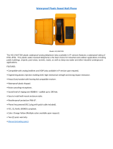
The OM-SGD-24-M-IP is a smart IP-67 graphics display with a 320 x 240 pixel (QVGA)
color display and USB programming interface.
Using the PanelPilot software (available for Windows XP, 2000, Vista and Windows 7), users are able to choose from an ever-increasing
number of congurations which can then be customized to their needs. The additional voltmeter types and other functions are available
through www.omega.com.
Colors, text labels, splash screen and input voltage scaling can all be customized by the user through the software and then uploaded
to the OM-SGD-24-M-IP through the USB connection. When setup is complete, the settings can be saved and then uploaded to the
meter using the supplied USB cable. Panel or enclosure installation of the nished module is simple, using the 32mm nut and the IP67
connector supplied with the unit.
OM-SGD-24-M-IP
Waterproof Smart
Graphics Display
ORDERING INFORMATION
Standard Display
(Panel meter, xing kit,
IP-67 connector, quick start
guide)
Current Loop Display
(Panel meter, xing kit,
IP-67 connector, quick start
guide)
OM-SGD-24-M-IP
OM-SGD-24-M-IP420
USB Cable
(Type A to mini-B)
2m Rightangle cable with
IP-67 connector
OM-CABLE-USB A-MF
OM-CABLE-IP-12W-RA
* Depending on user calibration settings
** The OM-SGD-24-M-IP uses a programmable gain amplier. There are 8 different voltage ranges, to optimise the resolution. See page 2 for details.
*** Voltage dependent. See graph on Page 2.
Specications Minimum Typical Maximum Unit
Accuracy 0.05 0.1 %
Linearity ±1* Count
Sample rate 3 Samples/second
Operating temperature range 0 (+32) +40 (+104) °C (°F)
Supply voltage 4 30 V d.c.
Measurement voltage (single ended only) ** 0 40 V d.c.
Measurement current (4-20mA version) 4 20 mA
Supply current *** 35 190 mA

Specications liable to change without prior warning Data Sheet - Issue 1 SL
www.omega.com
IP67 CONNECTION
Connector Pin Functions
1 ESPI-CS2 -SPI chip select
2 ESPI-MISO - SPI master input, slave output
3 ESPI-CLK - SPI serial clock
4 ESPI-MOSI - SPI master output, slave input
5 SDA - Serial data
6 SCL - Serial clock
7 ALM2 - Alarm output 2
8 ALM1 - Alarm output 1
9 IN1 - Analog voltage input 1 (maximum of 40V d.c. w.r.t 0v)
10 IN2 - Analog voltage input 2 (maximum of 40V d.c. w.r.t 0v)
11 0V - 0V power supply input
12 V+ - Positive power supply input (4V – 30V d.c.)
Connector plug options
OM-SGD-24-M-IP
Waterproof Smart Graphics Display
Twist lock, eld installable connector with solder bucket pins.
Seals for Cable OD=4.5mm~7.0mm
Twist lock connector with right angle overmoulded strain relief.
Cable length 2m.
10
1
2
3
11 12
9
8
7
6
5
4

Specications liable to change without prior warning Data Sheet - Issue 1 SL
www.omega.com
OM-SGD-24-M-IP
Waterproof Smart Graphics Display
VOLTAGE INPUT
0
100
200
4 17
30
Current (mA)
Voltage (V)
Typical Supply Current
USB Connection
Display
The OM-SGD-24-M-IP features 2 voltage inputs, which use a Programmable Gain Amplier (PGA) to make the best use of available
resolution (the smallest voltage range offers the highest resolution)*. Each channel can be programmed independently, with the option
of eight different input voltage ranges:
A ‘Type A to Mini-B’ USB cable is required to program and customize the OM-SGD-24-M-IP by unscrewing the 4xM3 screws and removing
the back cover. The packing tray supplied can be used as a jig to hold the module and to avoid disconnecting the 12 way connector from
the PCB inside.
The device will be powered for programming via USB.
It typically takes between 10 and 30 seconds to send a conguration, with an additional 5 seconds needed for the hardware to reset.
The display is a 2.4” TFT panel, with a resolution of 320 x 240 pixels and a 16-bit color depth. Any graphics that are uploaded to the meter
are automatically converted to this specication.
Voltage Range (V) Resolution (mV)
0 - 1.25 0.3
0 - 2.5 0.6
0 - 4 1.0
0 - 5 1.2
0 - 8 2.0
0 - 10 2.4
0 - 20 4.9
0 - 40 9.8
The input voltage range is decided using the two voltages that the user enters in
the scaling section of the Panel Pilot software. The software uses the smallest
range available, which can accommodate both of the voltages entered by the
user. The absolute maximum voltage input is 40V d.c.
For example:
Entering a voltage scale of 0 – 30V in the software will use the 0 – 40V range.
Entering a voltage scale of 0 – 3V in the software will use the 0 – 4V range.
Entering a voltage scale of 5 – 15V in the software will use the 0 – 20V range.
Note: V+, IN1 and IN2 share a common ground (i.e. not oating or isolated from
each other).
*For the 4-20mA model, the 0-2.5 range is used.
(4-20mA)

Specications liable to change without prior warning Data Sheet - Issue 1 SL
www.omega.com
OM-SGD-24-M-IP
Waterproof Smart Graphics Display
PANEL MOUNTING
The OM-SGD-24-M-IP can be tted into panels of up to 10.5mm deep. A
rubber seal is included to seal the mounting hole when the 32mm nut is
fully tightened. Panel mounting hole cut-out is DIA 33mm.
DIMENSIONS
All dimensions in mm [inches]
85.8 3.4
62.7 2.5
V.A 49.0
1.9
V.A 36.7
1.4
13.7 0.5
16.5 0.6
32.0 1.3
28.2 1.1
40.0 1.6
4 x M3 Screws

Specications liable to change without prior warning Data Sheet - Issue 1 SL
www.omega.com
OM-SGD-24-M-IP
Waterproof Smart Graphics Display
MEASURING A VOLTAGE SOURCE
MEASURING 0-2 AMPS CURRENT RANGE
Use a 1 Ω resistor, with a 4W rating.
Setup scaling in software: 0V = 0.00 and 2V = 2.00
MEASURING 0-100V (d.c. only)
Input a known voltage of between 0 and 100V (V1)
Measure the voltage between IN1 and 0V (V2)
Setup scaling in software: 0V = 0.0
V2 = V1 (Enter with the same number of decimal points, i.e 50.0)
V+
0V
IN1
4 - 30 V
0V
0 - 40V
4 - 30V
0V
V+
0V
IN1
0 - 2A
4W
4 - 30V
0V
V+
0V
IN1
100K
910K
0 - 100V
(V1)
V2
VARIOUS OPERATING MODES
VARIOUS OPERATING MODES (4-20mA version)
MEASURING 4-20mA
Power supply to meter must be fully oating
(isolated from the 4-20mA current loop)
Each OM-SGD must be powered from a seperate, fully
oating, power supply
USING TWO OM-SGD DISPLAYS IN SAME INSTALLATION
V+
(100R)
0V
I+
4 - 20mA 4 - 20mA
I-
IN1
4 - 20mA
4 - 30V
0V
4 - 30V
0V
V+
0V
IN1
I+
I-
PSU 1
4 - 30V
0V
V+
0V
IN1
I+
I-
PSU 2
V Loop
V+
+5
0V
USB
(100R)
0V
I+
4 - 20mA
I-
IN1
V Loop

Specications liable to change without prior warning Data Sheet - Issue 1 SL
www.omega.com
PANELPILOT SOFTWARE
Omega’s PanelPilot software is available for download free of charge from www.omega.com. Easy to install and use, the control software
runs under Windows XP, Vista and 7 and 8. The software is used to setup the appearance and operation of the meter and then upload these
settings to the meter.
Multiple types of voltmeter are supplied with the software. See www.omega.com for details of available meters.
The software allows the following parameters to be congured:
• Meter type
• Text labels (including units and graph labels)
• Background, graph segment and text colors
• Input scaling / calibration (at two points)
• Decimal points (entered during scaling)
• Splashscreen image selection (to display a
user image, such as a logo, when the meter is powered up)
VARIOUS OPERATING MODES (4-20mA version) continued
MEASURING 4-20mA
USING A USB POWER SUPPLY
DIGITAL HOLD
DIGI1 will hold the display
ALARM OUTPUT
Applications that feature an alarm can be connected as above.
ALM1 must not sink more than 10mA maximum each. If supply
voltage varies, use an appropriate voltage regulator.
V+
(100R)
0V
I+
4 - 20mA 4 - 20mA
I-
IN1
4 - 20mA
4 - 30V
0V
4 - 30V
0V
V+
0V
IN1
I+
I-
PSU 1
4 - 30V
0V
V+
0V
IN1
I+
I-
PSU 2
V Loop
V+
+5
0V
USB
(100R)
0V
I+
4 - 20mA
I-
IN1
V Loop
4 - 30V
0V
I+
I-
4 - 30V
R
R = (V
S
- V
L
)
I
L
V
S
= Supply voltage
V
L
= LED Voltage drop
I
L
= LED current
DIGI1
IN1
I+
I-
ALM1
IN1
4 - 30V
0V
I+
I-
4 - 30V
R
R = (V
S
- V
L
)
I
L
V
S
= Supply voltage
V
L
= LED Voltage drop
I
L
= LED current
DIGI1
IN1
I+
I-
ALM1
IN1
4 - 30V
0V
I+
I-
4 - 30V
R
R = (VS - VL)
I
L
V
S
= Supply voltage
V
L
= LED Voltage drop
I
L
= LED current
DIGI1
IN1
I+
I-
ALM1
IN1
OM-SGD-24-M-IP
Waterproof Smart Graphics Display

OMEGA’s policy is to make running changes, not model changes, whenever an improvement is possible. This affords
our customers the latest in technology and engineering.
OMEGA is a registered trademark of OMEGA ENGINEERING, INC.
© Copyright 2014 OMEGA ENGINEERING, INC. All rights reserved. This document may not be copied, photocopied,
reproduced, translated, or reduced to any electronic medium or machine-readable form, in whole or in part, without the
prior written consent of OMEGA ENGINEERING, INC.
FOR WARRANTY RETURNS, please have the
following information available BEFORE
contacting OMEGA:
1. Purchase Order number under which the product
was PURCHASED,
2. Model and serial number of the product under
warranty, and
3. Repair instructions and/or specific problems
relative to the product.
FOR NON-WARRANTY REPAIRS,
consult OMEGA
for current repair charges. Have the following
information available BEFORE contacting OMEGA:
1. Purchase Order number to cover the COST
of the repair,
2. Model and serial number of the product, and
3. Repair instructions and/or specific problems
relative to the product.
RETURN REQUESTS/INQUIRIES
Direct all warranty and repair requests/inquiries to the OMEGA Customer Service Department.
BEFORE RETURNING ANY PRODUCT(S) TO OMEGA, PURCHASER MUST OBTAIN AN AUTHORIZED
RETURN (AR) NUMBER FROM OMEGA’S CUSTOMER SERVICE DEPARTMENT (IN ORDER TO AVOID
PROCESSING DELAYS). The assigned AR number should then be marked on the outside of the return
package and on any correspondence.
The purchaser is responsible for shipping charges, freight, insurance and proper packaging to prevent
breakage in transit.
WARRANTY/DISCLAIMER
OMEGA ENGINEERING, INC. warrants this unit to be free of defects in materials and workmanship for a
period of 13 months from date of purchase. OMEGA’s WARRANTY adds an additional one (1) month
grace period to the normal one (1) year product warranty to cover handling and shipping time. This
ensures that OMEGA’s customers receive maximum coverage on each product.
If the unit malfunctions, it must be returned to the factory for evaluation. OMEGA’s Customer Service
Department will issue an Authorized Return (AR) number immediately upon phone or written request.
Upon examination by OMEGA, if the unit is found to be defective, it will be repaired or replaced at no
charge. OMEGA’s WARRANTY does not apply to defects resulting from any action of the purchaser,
including but not limited to mishandling, improper interfacing, operation outside of design limits,
improper repair, or unauthorized modification. This WARRANTY is VOID if the unit shows evidence of
having been tampered with or shows evidence of having been damaged as a result of excessive corrosion;
or current, heat, moisture or vibration; improper specification; misapplication; misuse or other operating
conditions outside of OMEGA’s control. Components in which wear is not warranted, include but are not
limited to contact points, fuses, and triacs.
OMEGA is pleased to offer suggestions on the use of its various products. However,
OMEGA neither assumes responsibility for any omissions or errors nor assumes liability for
any damages that result from the use of its products in accordance with information provided
by OMEGA, either verbal or written. OMEGA warrants only that the parts manufactured by the
company will be as specified and free of defects. OMEGA MAKES NO OTHER WARRANTIES OR
REPRESENTATIONS OF ANY KIND WHATSOEVER, EXPRESSED OR IMPLIED, EXCEPT THAT OF
TITLE, AND ALL IMPLIED WARRANTIES INCLUDING ANY WARRANTY OF MERCHANTABILITY
AND FITNESS FOR A PARTICULAR PURPOSE ARE HEREBY DISCLAIMED. LIMITATION OF
LIABILITY: The remedies of purchaser set forth herein are exclusive, and the total liability of
OMEGA with respect to this order, whether based on contract, warranty, negligence,
indemnification, strict liability or otherwise, shall not exceed the purchase price of the
component upon which liability is based. In no event shall OMEGA be liable for
consequential, incidental or special damages.
CONDITIONS: Equipment sold by OMEGA is not intended to be used, nor shall it be used: (1) as a “Basic
Component” under 10 CFR 21 (NRC), used in or with any nuclear installation or activity; or (2) in medical
applications or used on humans. Should any Product(s) be used in or with any nuclear installation or
activity, medical application, used on humans, or misused in any way, OMEGA assumes no responsibility
as set forth in our basic WARRANTY/DISCLAIMER language, and, additionally, purchaser will indemnify
OMEGA and hold OMEGA harmless from any liability or damage whatsoever arising out of the use of the
Product(s) in such a manner.

M5534/0116
Where Do I Find Everything I Need for
Process Measurement and Control?
OMEGA…Of Course!
Shop online at omega.com
SM
TEMPERATURE
MU
Thermocouple, RTD & Thermistor Probes, Connectors, Panels & Assemblies
MU
Wire: Thermocouple, RTD & Thermistor
MU
Calibrators & Ice Point References
MU
Recorders, Controllers & Process Monitors
MU
Infrared Pyrometers
PRESSURE, STRAIN AND FORCE
MU
Transducers & Strain Gages
MU
Load Cells & Pressure Gages
MU
Displacement Transducers
MU
Instrumentation & Accessories
FLOW/LEVEL
MU
Rotameters, Gas Mass Flowmeters & Flow Computers
MU
Air Velocity Indicators
MU
Turbine/Paddlewheel Systems
MU
Totalizers & Batch Controllers
pH/CONDUCTIVITY
MU
pH Electrodes, Testers & Accessories
MU
Benchtop/Laboratory Meters
MU
Controllers, Calibrators, Simulators & Pumps
MU
Industrial pH & Conductivity Equipment
DATA ACQUISITION
MU
Data Acquisition & Engineering Software
MU
Communications-Based Acquisition Systems
MU
Plug-in Cards for Apple, IBM & Compatibles
MU
Data Logging Systems
MU
Recorders, Printers & Plotters
HEATERS
MU
Heating Cable
MU
Cartridge & Strip Heaters
MU
Immersion & Band Heaters
MU
Flexible Heaters
MU
Laboratory Heaters
ENVIRONMENTAL
MONITORING AND CONTROL
MU
Metering & Control Instrumentation
MU
Refractometers
MU
Pumps & Tubing
MU
Air, Soil & Water Monitors
MU
Industrial Water & Wastewater Treatment
MU
pH, Conductivity & Dissolved Oxygen Instruments
/