Page is loading ...

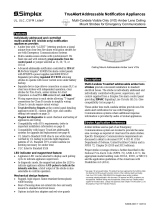
Features
Individually addressed and controlled
multi-candela S/V (speaker/visible) notification
appliances provide:
Multi-candela xenon strobe with synchronized 1 Hz
flash rate and with intensity programmable from the
control panel or jumper selected as 15, 30, 75, or
110 cd
Advanced addressable notification controlled by IDNAC
SLCs providing regulated 29 VDC allowing strobes to
operate with lower current even under battery backup
Wiring supervision to each strobe allowing “T-tapped”
connections for Class B circuits to simplify wiring
(Class A circuits require in/out wiring)
TrueAlert Device Reports at the control panel detailing
appliance point ID, custom label, type, and candela
setting (see sample on page 2)
Magnet test diagnostics to assist checkout and testing of
appliances and wiring
Compatibility with ADA requirements; (refer to
important installation information on page 3)
Compatibility with legacy TrueAlert addressable
systems for upgrade and replacement (see page 4)
Strobe operation is listed to UL 1971 and ULC-S526*
LED indicator and magnet test feature:
Appliance LED can be selected to display each polling
cycle to indicate appliance supervision
In diagnostic mode, the magnet test pulses the LED to
indicate appliance address AND pulses to indicate the
intensity selection; a brief output of the strobe is also
selectable to confirm operation
Mechanical design features:
Rugged, high impact, flame retardant thermoplastic
housings are available for wall or ceiling mount
Wall mount housings are available in red or white
Wall mount options include electrical box adapters,
separate covers to convert color, and red wire guards
Ceiling mount housing is white
Audible notification appliance (speaker):
High quality voice and tone reproduction with taps for
¼, ½, 1, or 2 W, at 25 or 70.7 VRMS
Speakers have capacitor input for connection to DC
supervised NACs and are wired separately from strobes
Listed to UL 1480 and ULC S541*
Compliant with NFPA 72, 520 Hz Low Frequency
Signal Requirements for Sleeping Areas
* See page 2 for additional listing details and wire guard listings. This product has been
approved by the California State Fire Marshal (CSFM) pursuant to Section 13144.1 of the
California Health and Safety Code. See CSFM Listing 7320-0026:322 for allowable values
and/or conditions concerning material presented in this document.
Accepted for use – City
of New York Department of Buildings – MEA35-93E. Additional listings may be applicable;
contact your local Simplex product supplier for the latest status. Listings and approvals
under Simplex Time Recorder Co. are the property of Tyco Fire Protection Products.
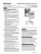
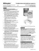
Wall and Ceiling Mount S/Vs with Addressable Strobes
Description
Multi-Candela TrueAlert S/Vs with speaker and
addressable strobe provide convenient installation to
standard electrical boxes with extensions. The strobe is
individually addressed and individually controlled with
power, supervision, and control supplied from a Simplex
fire alarm control panel providing IDNAC Signaling Line
Circuits (SLCs). (See compatibility list on page 4.)
Speakers are wired separately.
Strobe Application Reference
Proper selection of visible notification is dependent on
occupancy, location, local codes, and proper applications
of: the National Fire Alarm and Signaling Code
(NFPA 72), ANSI A117.1; the appropriate model
building code: BOCA, ICBO, or SBCCI; and the
application guidelines of the Americans with Disabilities
Act (ADA).
IDNAC SLC Operation Advantage
TrueAlert S/V Appliances with Addressable
Strobes on IDNAC SLCs provide visible notification
using a single two-wire circuit that also confirms
connection to the individual notification appliance’s
electronic circuit. This operation increases circuit
supervision integrity by providing supervision that
extends beyond the appliance wiring connections.
TrueAlert Addressable Notification Appliances
UL, ULC, CSFM Listed; FM Approved; Multi-Candela Speaker/Visible
MEA (NYC) Acceptance* (S/V) Appliances
S4906-0006-8 2/2015

IDNAC SLC Operation Advantage (Cont’d)
Reduced current allows efficient IDNAC SLC
operation. With IDNAC SLCs, a constant 29 VDC
source voltage is maintained, even during battery standby,
allowing strobes to operate at higher voltage with lower
current and ensuring a consistent current draw and voltage
drop margin under both primary power and secondary
battery standby. Efficiencies include wiring distances up to
2 to 3 times farther than with conventional notification, or
support for more appliances per IDNAC SLC, or use of
smaller gauge wiring, or combinations of these benefits, all
providing installation and maintenance savings with high
assurance that appliances that operate during normal system
testing will operate during worst case alarm conditions.
Reducing Installation and Testing Time. With
separate controls on the same two-wire SLC, installation
time and expense for both retrofit and new construction can
be significantly reduced. When Class B wiring is used,
wiring can be “T” tapped, allowing more savings in
distance, wire, conduit (size and utilization), and overall
installation efficiency. Use of the magnet test feature
improves installation efficiency. TrueAlert device reports
conveniently identify information about each connected
appliance.
TrueAlert Addressable Wiring Isolator
Isolator Model 4905-9929 is available for remote
mounting on TrueAlert addressable circuits to isolate short
circuited wiring from functioning wiring. (Refer to data
sheet S4905-0001 for additional information.)
TrueAlert Addressable Diagnostics
Test Features. Controllers can be selected to pulse each
appliance’s LED when it receives a supervision poll. When
the controller is selected for diagnostic mode, the appliance
magnet test feature provides a response at the individual
appliance being tested.
Silent Appliance Magnet Test. In this test mode, in
response to the magnet test, the appliance LED pulses
sequentially to conveniently indicate the appliance’s address.
Operational Appliance Testing. In this test mode, after
the address is indicated by pulsing the appliance LED, the
strobe will briefly flash to indicate proper operation.
TrueStart Instrument Two (TSIT). The 2nd generation
of the Simplex TrueStart Test Instrument adds testing of
IDNAC SLC wiring and TrueAlert (and TrueAlert ES)
appliances to its ability to test IDCs, NACs, and IDNet
communications before connection to the control panel.
Please contact your local Simplex representative for
additional information.
Service Port
P
age 1
REPORT 5 : TrueAlert Device Report 12:34:56am T
U
E
2
7
-
J
an
-
1
4
POINT ID
CUSTOM LABEL
DEVICE
T
YPE
CANDELA
T14-1-1 Location Label . . . up to 40 characters
V
/O 15
T14-1-2 Break Room 5
S
/V 110
T14-1-3 Boiler Room
S
/V 75
T14-1-4 Elec. Room 7
S
/V 30
2 S4906-0006-8 2/2015
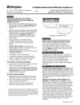
Multi-Candela Addressable S/Vs
Model Lettering Listings Housing Color Mounting Dimensions Description
4906-9251 White FIRE
UL & ULC
Red
Wall
7 ¼” H x 5” W x 2 ⅝” D
(184 mm x 127 mm x 67 mm)
Multi-Tapped
Speaker with
Multi-Candela
Addressable Strobe;
intensity selectable
as: 15, 30, 75, or 110
candela
4906-9253 Red FIRE White
4906-9254 Red FIRE
UL
White Ceiling
7 ½” (191 mm) diameter speaker
housing, ½” (13 mm) deep; lens extends
2 ⅝” (67 mm) above housing;
extension into box = 2 ¾” (70 mm)
4906-9255 Blank
4906-9256 Red ALERT
4906-9257 Red FIRE ULC
Wall Mount S/V Adapters, Replacement Covers, Wire Guard; Ceiling Mount Tile Bridge
Model Description Dimensions
4905-9946 Surface Mount Red Adapter Skirt
Required when mounting to surface
mounted electrical box, 4” square, 1 ½”
deep with 1 ½” deep extension
7 ¾” H x 5 ⅜” W x 3
3
⁄
16
” D
(197 mm x 137 mm x 81 mm)
depth with S/V = 5 ⅞” (149 mm)
4905-9947 Surface Mount White Adapter Skirt
4905-9903
Adapter Plate, red, required to mount S/V on 2975-9145 mounting box
(typically for retrofit)
8
5
⁄
16
" H x 5 ¾" W x 0.060” Thick
(211 mm x 146 mm x 1.5 mm)
2975-9145
Mounting Box, red, for surface or flush mount, requires adapter plate 4905-9903
(this box may be available for retrofit applications)
7 ⅞" H x 5 ⅛" W x 2 ¾" D
(200 mm x 130 mm x 70 mm)
4905-9996 Red Wall Mount S/V Replacement Cover with white “FIRE” lettering
7 ¼” H x 5” W x 1 ⅜” D
(184 mm x 127 mm x 35 mm)
4905-9997 White Wall Mount S/V Replacement Cover with red “FIRE” lettering
4905-9998
Red Wire Guard for Wall Mount S/V; with mounting plate, compatible with surface
and semi-flush boxes (UL listed by Space Age Electronics Inc.)
8 ⅜” H x 6
1
⁄
16
” W x 3 ¼” D
(213 mm x 154 mm x 79 mm)
2905-9946 Tile Bridge for Ceiling Mount S/Vs See diagram on page 3
Product Selection
TrueAlert Device Reports Reference

3 S4906-0006-8 2/2015
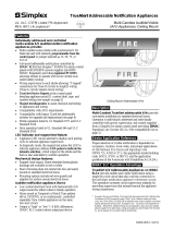
Standard Electrical Box Mounting
4" (102 mm) square box, 1-1/2"
(38 mm) deep, with a 4" square box
extension, 1-1/2" deep, by others
Mounting to 2975-9145 Box
2975-9145 Box
4905-9903
Adapter Plate
LED
indicator
Address
DIPswitch
Transparent housing and lens assembly
Wiring input
terminals and
speaker tap
selection are
accessible
from rear
Speaker
assembly
Strobe
assembly
Removable cover
(tool required)
Magnetic test location
Strobe intensity viewing slot
Intensity selection plug, accessible only from rear of
housing; factory setting is FACP, controlled by panel
110
75
30
15
FACP
75
76
77
78
79
80
81
82
83
84
85
90 80 70 60 50 40 30 20 10 0 10 20 30 40 50 60 70 80 90
Angular Displacement (Degrees) on Horizontal Axis
Sound Pressure Level (dB) at 10 ft (3 m)
Speaker Directional Characteristics;
NOTE: Applicable for Wall Mount or Ceiling Mount S/V
4" (102 mm) square box
profile, 1-1/2" (38 mm)
deep with 1-1/2" extension
Surface mount conduit and
box shown for reference
S/V
Optional 4905-9998
Wire Guard
Surface mount adapter skirt, 3-3/16"
(81 mm) deep, required for this
mounting method: 4905-9946, Red;
4905-9947, White (conduit knockouts
are provided on all four sides)
Surface Mounting Reference
Showing Optional Wire Guard
IMPORTANT ! INSTALLATION
MOUNTING HEIGHT REFERENCE
NFPA 72 requires
that the entire lens
be not less than
80" and not greater
than 96" above the
finished floor.
4" square box
outline
4" (102 mm)
1-1/2" (38 mm)
82"
(2.1 m)
minimum
78-1/2"
(2 m)
minimum
2975-9145
box outline
C
L
2 kHz
4 kHz
4" (102 mm) square, 1-1/2" (38 mm) deep
box with 1-1/2" extension (by others)
Wiring input
terminals and
speaker tap
selection are
accessible from
rear of speaker
housing
15
11
0
75
30
FACP
Strobe intensity viewing
slot
Intensity selection plug,
accessible only from rear of lens
housing; factory setting is
FACP, controlled by panel
Address DIPswitch is behind strobe assembly;
select address before inserting into housing
Magnetic test location
Magnet
test
location
Bottom view
LED indicator
13-3/8" (340 mm)
1/4" diameter (6 mm)
holes, 4 places
0.024" thick sheet
metal, folded with
1/2" lip each side
3-3/4" (95 mm) square
cutout, centered on plate
23-11/16"
(602 mm)
6-11/16"
(170 mm)
1/2" (13 mm)
2905-9946
Tile Bridge
Wall Mount Installation Reference
Ceiling Mount S/V Install Reference and Tile Bridge Dimensions

Tyco Fire Protection Products • Westminster, MA • 01441-0001 • USA S4906-0006-8 2/2015
www.simplex-fire.com
© 2015 Tyco Fire Protection Products. All rights reserved. All specifications and other information shown were current as of document revision date and are subject to change without notice.
TYCO, SIMPLEX, and the product names listed in this material are marks and/or registered marks. Unauthorized use is strictly prohibited. NFPA 72 and National Fire Alarm and
Signaling Code are registered trademarks of the National Fire Protection Association (NFPA).
Common Specifications (see page 2 for appliance dimensions)
Environmental 32° to 122° F (0° to 50° C); 10% to 93%, non-condensing at 100° F (38° C)
Connections
Terminal blocks for 18 AWG to 12 AWG (0.82 mm
2
to 3.31 mm
2
); two wires per terminal for
in/out wiring
Installation Instructions 579-808
Speaker General Specifications
Input Voltage 25 or 70.7 VRMS, see Note 1 below
Power Taps ¼, ½, 1, and 2 W
Frequency Response Fire Alarm = 400 to 4000 Hz General Signaling = 125 to 12 kHz
Speaker Output Ratings @ 10 ft (3 m) (see Note below)
Wattage Tap ¼ W ½ W 1 W 2 W
UL Listed Models, Reverberant Chamber Test, per UL 1480 76 dBA 79 dBA 82 dBA 85 dBA
Wall Mount Models 4906-9251 and 4906-9253, Anechoic
Chamber Test, per ULC-S541
77 dBA 80 dBA 83 dBA 86 dBA*
Ceiling Mount Model 4906-9257, Anechoic
Chamber Test per ULC-S541
25 VRMS Input 81.6 dBA 84.3 dBA 87.1 dBA* 89.7 dBA*
70.7 VRMS Input 80.9 dBA 84.1 dBA 87.3 dBA* 90.2 dBA*
* NOTE: Select taps as indicated to satisfy the ULC fire alarm applications requirement of 85 dBA minimum
Polar Dispersion Reference (per ULC-S541 Anechoic Chamber
Testing)
Attenuation Angle Attenuation Angle
-3 dB +/- 30° off-axis -6 dB +/- 55° off-axis
Strobe Specifications
Typical Operating Voltage Range
23 VDC to 31 VDC, Special Application (see below for 17 VDC rating)
Supervisory Requirements
1 unit load (= 0.8 mA control panel current)
Flash Rate and Synchronized SLC Loading 1 Hz; with up to 46 synchronized strobes maximum per NAC
Wall Mount
Appliances
Candela Setting
15 cd 30 cd 75 cd 110 cd
23 VDC RMS Current Ratings, for
connection to IDNAC Addressable SLCs
50 mA 75 mA 137 mA 190 mA
Ceiling Mount
Appliances
23 VDC RMS Current Ratings, for
connection to IDNAC Addressable SLCs
60 mA 92 mA 180 mA 240 mA
Note: Speakers are for connection to conventional fire alarm audio circuits. Anechoic speaker output ratings are typically more
representative of actual installed sound output.
Compatible Controller
Data Sheet
Reference
Controller Output
Available Strobe
Intensity
Appliance Voltage
Minimum
4100ES or 4100U with TrueAlert Power Supply S4100-0031
TrueAlert
Addressable SLC
15, 30, 75, and
110 cd
17
VDC 4009 TPS, Remote TrueAlert Power Supply S4100-0037
TrueAlert Addressable Controller (4009T) S4009-0003
Electrical Ratings Difference for Retrofit Applications
Voltage Range 17 VDC to 31 VDC, Special Application
Candela Setting 15 cd 30 cd 75 cd 110 cd
17 VDC RMS Current Ratings, use
when connected to TrueAlert
Addressable SLCs per above
Wall
Mount
Appliances
64 mA 98 mA 187 mA 253 mA
Ceiling Mount
Appliances
76 mA 128 mA 242 mA 328 mA
Compatible Controllers
Data Sheet
Reference
Controller Output
IDNAC SLC Output
Voltage
Appliance Voltage
Design Reference
4100ES with EPS+ or EPS Power Supply S4100-0100
IDNAC SLC
29 VDC
(regulated)
23 VDC
(with 6 VDC drop)
4009 IDNAC Repeater S4009-0004
4007ES with IDNAC Notification S4007-0002
4010ES with ESS Enhanced System Supply S4010-0011
S/V Specifications
TrueAlert Strobe LEGACY Compatibility Reference
IDNAC SLC Controller Compatibility Reference
/