Page is loading ...

8508341
Gateway
™
910 Series
System Manual
September 2001

Notices
Copyright © 2001 Gateway, Inc.
All Rights Reserved
4545 Town Centre Court
San Diego, CA 92121 USA
All Rights Reserved
This publication is protected by copyright and all rights are reserved. No part of it may be reproduced or
transmitted by any means or in any form, without prior consent in writing from Gateway.
The information in this manual has been carefully checked and is believed to be accurate. However, changes
are made periodically. These changes are incorporated in newer publication editions. Gateway may improve
and/or change products described in this publication at any time. Due to continuing system improvements,
Gateway is not responsible for inaccurate information which may appear in this manual. For the latest product
updates, consult the Gateway Web site at www.gateway.com. In no event will Gateway be liable for direct,
indirect, special, exemplary, incidental, or consequential damages resulting from any defect or omission in
this manual, even if advised of the possibility of such damages.
In the interest of continued product development, Gateway reserves the right to make improvements in this
manual and the products it describes at any time, without notices or obligation.
Trademark Acknowledgments
1-800-GATEWAY, ActiveCPR, ALR, AnyKey, black-and-white spot design, CrystalScan, Destination, DestiVu,
EZ Pad, EZ Point, Field Mouse, Gateway 2000, Gateway Country, gateway.net, Gateway stylized logo, Perfect
Scholar, Solo, TelePath, Vivitron, stylized “G” design, and “Yo u ’ve got a friend in the business” slogan are
registered trademarks and black-and-white spotted box logo, GATEWAY, Gateway Astro, Gateway@Work,
Gateway Connected touch pad, Gateway Connected music player, Gateway Cyber:)Ware, Gateway
Education:)Ware, Gateway Flex Case, Gateway Gaming:)Ware, Gateway GoBack, Gateway Gold, Gateway
Learning:)Ware, Gateway Magazine, Gateway Micro Server, Gateway Money:)Ware, Gateway Music:)Ware,
Gateway Networking Solutions, Gateway Online Network (O.N.) solution, Gateway Photo:)Ware, Gateway
Professional PCs, Gateway Profile, Gateway Solo, green stylized GATEWAY, green stylized Gateway logo,
Gateway Teacher:)Ware, Gateway Video:)Ware, HelpSpot, InforManager, Just click it!, Learn@Gateway, Kids
BackPack, People Rule, SERVE-TO-ORDER, Server Watchdog, SpotShop, Spotshop.com, and Your:)Ware
are trademarks of Gateway, Inc. Intel, Intel Inside logo, and Pentium are registered trademarks and MMX is
a trademark of Intel Corporation. Microsoft, MS, MS-DOS, and Windows are trademarks or registered
trademarks of Microsoft Corporation. All other product names mentioned herein are used for identification
purposes only, and may be the trademarks or registered trademarks of their respective companies.

Contents i
Contents
Preface..............................................................v
Conventions used in this manual .......................................v
Getting additional information . . ........................................vi
1 Features .........................................................1
Standardfeatures ...................................................1
Front .............................................................2
Back..............................................................3
Interior ............................................................5
System board ......................................................7
2SystemSetup...................................................9
Settingupyourserver................................................9
Startingyourserver.................................................10
Understanding the Power-On Self-Test ..............................11
Settinguptheoperatingsystem....................................11
Turningoffyourserver ..............................................12
Restartingyourserver...............................................13
3 Case Access ...................................................15
Preventingstaticelectricitydischarge...................................15
Openingthecase ..................................................16
Removingthecoverpanel ........................................17
Removingthebezel .............................................19
Closingthecase ...................................................21
Reinstallingthebezel ............................................21
Reinstalling the cover panel .......................................22
4 Replacing or Adding System Components .....................23
Replacing or adding drives ...........................................23
Preparing to replace or add a drive . . . ..............................23
Drivecablingconsiderations.......................................24
ReplacingtheCDdrive...........................................25
Replacingthediskettedrive .......................................28
Addinga5.25-inchor3.5-inchremovablemediadrive ..................30
Replacingtheharddrive..........................................33
Adding an additional hard drive ....................................35
Replacing or adding memory . . .......................................37

ii Contents
Replacingtheprocessor..............................................40
Adding or replacing expansion cards ....................................44
Replacingthebattery ................................................49
Replacing the system board ...........................................52
Replacingthepowersupply ...........................................55
5 Using the BIOS Setup Utility ....................................57
About the BIOS Setup utility ...........................................57
Settingthesystemboardjumpers ......................................60
Updating the BIOS . . . ...............................................61
Recovering from a failed BIOS update . . .............................61
6 Managing Your Server ..........................................63
Protecting against power source problems . . .............................63
Surge suppressors ...............................................63
Line conditioners . ...............................................64
Uninterruptible power supplies ......................................64
Maintaining and managing your hard drive . . .............................65
Hard drive maintenance utility ......................................65
Harddrivemanagementpractices...................................66
Protectingtheserverfromviruses...................................68
Systemadministrationandcontrol ......................................70
ManageX Event Manager . . . ......................................70
SNMPagent....................................................70
Serversecurity ..................................................71
Systemrecovery ....................................................72
Creatingastartupdiskette.........................................72
Keeping a record of system configuration .............................72
UsingyourServerCompanionCD ..................................72
7 Troubleshooting ................................................73
Introduction ........................................................73
Troubleshootingchecklist .............................................73
Verifyingyourconfiguration ........................................74
Troubleshooting guidelines . . ......................................74
Troubleshooting the battery installation . . .............................74
CDdriveproblems ..................................................75
Harddriveproblems .................................................76
Memoryandprocessorproblems.......................................77
Modem problems ...................................................78
Peripheral device/adapter problems .....................................79
Printerproblems ....................................................81

Contents iii
Systemproblems...................................................82
Videoproblems ....................................................84
Error messages ....................................................87
Beepcodes .......................................................91
A Safety, Regulatory, and Legal Information .....................93
B Reference Data ................................................105
Specifications.....................................................105
Systemspecifications ...........................................106
Mechanical specifications . . ......................................107
Environmentalspecifications......................................107
Electricalspecifications..........................................108
System I/O addresses ..............................................109
Memorymap .....................................................111
Interrupts ........................................................112
DMAusage ......................................................113
Index..............................................................115

Conventions used in this manual v
Preface
Conventions used in this manual
Throughout this manual, you will see the following conventions:
Convention Description
ENTER Keyboard key names are printed in small capitals.
C
TRL+ALT+DEL A plus sign means to press the keys at the same time.
Setup Commands to be entered, options to select, and messages that appear
on your monitor are printed in bold.
User’s Guide Names of publications are printed in italic.
Viewpoint All references to front, rear, left, or right on the server are based on the
server being in a normal, upright position, as viewed from the front.
Defined terms When new terms are introduced and defined, they will be shown in italic.
Important A note labeled important informs you of special
circumstances.
Caution A caution warns you of possible damage to equipment or
loss of data.
Warning A warning indicates the possibility of personal injury.

vi Preface
Getting additional information
Log on to the technical support area of www.gatewayatwork.com to find
information about your server or other Gateway products. Some types of
information that you can access are:
■ Hardware driver and program updates
■ Technical tips
■ Service agreement information
■ Technical documents and component information
■ Frequently asked questions (FAQs)
■ Documentation for peripheral devices or optional components
■ Online technical support
You can find additional documentation on the Server Companion CD (SCCD)
that came with your server.

Standard features 1
1
Features
Standard features
■ Intel
®
Celeron
™
or Pentium
®
III processor
■ Four dual in-line memory module (DIMM) sockets that support as much
as 2 gigabytes (GB) of PC133 Synchronous Dynamic Random Access
Memory (SDRAM)
■ Integrated ATI
®
video controller - Rage XL 4 MB PC100 SDRAM
■ Integrated Intel
®
10/100 Mbit per second Ethernet network support
■ Serverworks
™
Champion LC chip set
■ Three 32-bit/33 MHz and two 64-bit/66 MHz PCI slots that support
full-length, full-height PCI expansion cards
■ One 3.5 inch diskette drive, one CD drive, and one hard drive
■ Keyboard port, mouse port, one serial port, parallel port, video port, Local
Area Network (LAN) port, four Universal Serial Bus (USB) ports (two front
and two back)

2 Features
Front
CD drive reads data or plays audio CDs.
Diskette drive writes to and reads from 3.5-inch, 1.44 MB diskettes.
Power LED glows green when the server is on.
Additional drive bays lets you install additional 5.25-inch or 3.5-inch drives.
USB ports connect external Plug-n-Play devices that are automatically
configured when they are plugged into the server through one of these ports.
USB keyboards and mice are not supported. Use only PS/2 versions.
Power button turns the server on and off. It also enables sleep-mode in some
operating systems.
Diskette drive
Power button
CD drive
Power LED
USB ports
Additional
drive bays

Back 3
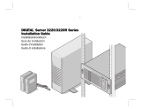
Back
Power connector connects to the server power cord. The other end of the
power cord plugs into an AC outlet or power strip.
Voltage selector switch sets the voltage for your area, either 115V or 230V.
Mouse port connects to a PS/2
®
(Personal System/2
®
) -compatible mouse.
Keyboard port connects to a PS/2-compatible keyboard.
USB ports connect to external Plug-n-Play devices that are automatically
configured when they are plugged into the server through one of these ports.
USB keyboards and mice are not supported. Use only PS/2 versions.
Serial port connects to serial devices.
Parallel port connects to a printer or other parallel device.
Serial port
Keyboard port
Power connector
USB ports
Voltage selector
switch
Parallel port
Release tab
Mouse port
Card retainer
thumbscrew
Video port
Kensington
lock slot
RJ-45 LAN port
Expansion
card slots
Release tab
Card retainer
Cover panel
thumbscrew

4 Features
Video port connects to the monitor interface cable.
RJ-45 LAN connector connects to the Ethernet network cable. The adjacent
indicator LEDs show LAN activity (yellow) and 100 Mbit speed (green).
Expansion card slots let you add additional cards to the system board.
Release tabs let you remove the cover panel.
Cover panel thumbscrew is used to securely fasten the cover panel to the
chassis.
Kensington lock slot lets you use a cable lock to secure the server and prevent
the cover panel from being removed.
Card retainer is used to secure expansion cards in place.
Card retainer thumbscrew is removed to open the card retainer.

Interior 5
Interior
Power supply is installed on the inside of the back panel and provides power
to the system board and all internal components.
System fan is installed beneath the power supply and vents heated air out
of the server.
System board is installed on the chassis frame stand-offs and connects to all
internal components with cable connectors.
Power supply release latch is used to secure the power supply in place.
Upper drive cage contains the diskette and CD drive and provides a mounting
location for an additional 5.25-inch and 3.5-inch drive.
Drive release latches are used to secure drives in place. There are three latches
on the upper drive cage and three on the lower drive cage. Locked and
unlocked positions are indicated by an open or closed padlock icon.
Hard drive is located in the lower drive cage and connects to the power supply
and system board.
Power
supply
System
board
System
fan
Power supply
release latch
Drive release
latch
Hard drive
Bezel tab
Lower drive
cage
Bezel
Upper drive
cage
Drive release
latch
Bezel tab

6 Features
Lower drive cage is located inside the chassis beneath the diskette drive and
contains the hard drive. It provides a mounting location for two additional
3.5-inch drives.
Bezel mounts to the front of the chassis.
Bezel tabs hold the bezel into place on the chassis.

System board 7
System board
A Keyboard port
B Mouse port
C Processor socket
D DIMM slots
E Main power connector
F Secondary IDE connector
G Primary IDE connector
A B
C
DE
F
G
I
J
H
N
M
LK
V
U
R
S
P
O
T
Q

8 Features
H Diskette drive connector
I Front panel connector
J Thumbscrew installation hole
K Front panel USB connector
L Hardware management connector
M Server configuration jumper block
N Battery
O 32-bit PCI slots
P 64-bit PCI slots
Q RJ-45 LAN connector
R Video port
S Processor fan connector
T Parallel port
U Serial port
V Back panel USB connector

Setting up your server 9
2
S
y
s
t
e
m
S
e
t
u
p
Settingupyourserver
Use the instructions on the poster that came with your server to set up your
hardware.
You can improve the safety of your working environment before setting up
your hardware by following these guidelines:
■ Use a clean, flat, and stable surface for your server. Allow at least 12 inches
at the rear of the server for cabling and air circulation.
■ Obtain a grounded (three-prong) AC surge-protected power strip. A
surge-protected power strip helps protect against AC power fluctuations.
■ Protect your server from extreme temperature and humidity. Do not
expose your server to direct sunlight, heater ducts, or other
heat-generating objects.
■ Keep your server away from equipment that generates magnetic fields,
such as unshielded stereo speakers. Even a telephone placed too close to
the server may cause interference.
■ Plug the server into a wall outlet or power strip that is easily accessible.
Important Keep the server boxes and packing material in case you
need to send the server to Gateway for repairs. If you
return your server in different packaging, your warranty
may be voided.

10 System Setup
Starting your server
Before you start your server for the first time:
■ Make sure that the voltage selector switch on the back of the server is
set to the correct voltage for your area. This switch is set at the factory
to the correct voltage (see “Back” on page 3 for the voltage selector switch
location).
■ Make sure all cables are firmly connected to the proper ports on the back
of the server.
■ Make sure the server and monitor are plugged into an AC outlet or power
strip and that the power strip is turned on.
To start the server:
1 Turn on any components connected to the server, such as a monitor,
printer or scanner.
2 Turn on the server. The power indicator light-emitting diode (LED) on
the front of the server remains lit (green) when the power is on.
If nothing happens when you turn on the server:
■ Make sure that the power cables are securely plugged in and that
your power strip (if you are using one) is plugged in and turned on.
■ Make sure the monitor is connected to the server, plugged into the
power strip or AC outlet, and turned on. You may also need to
adjust the brightness and contrast controls on the monitor.
Caution Make sure your server and peripherals are turned off and
unplugged from the power outlet when you connect
peripherals to the server, or you might damage the server
or the peripherals.

Starting your server 11
Understanding the Power-On Self-Test
When you turn on your server, the power-on self-test (POST) routine checks
the server memory and components. If POST finds any problems, the server
displays error messages. Write down any error messages that you see. If you
continue to have problems, these error messages may help Gateway Technical
Support diagnose the cause.
Press the T
AB key to see the startup POST messages. The default setting is quiet
mode (no startup information displayed).
Setting up the operating system
The first time you start your server, the operating system takes a few minutes
to set up. Refer to your operating system documentation for specific questions
regarding the operating system.
To complete the operating system setup for Windows 2000 Server:
1 After the server starts, the start-up wizard opens. Continue by clicking
Next.
2 Type the requested information in the appropriate text boxes. When you
have finished typing the information, continue by clicking
Next.
3 Continue following the instructions and selecting options in the start-up
wizard dialog boxes, clicking
Next to move through the dialog boxes, until
the wizard tells you to restart your server.
If you need to return to the previous dialog box to change any of your
entries, click
Back.
Important The server starts very quickly. If yourmonitor requires time
to warm up, you may not see the messages that are
displayedduringstartup.Ifyouarehavingproblems,you
may need to wait for the monitor to warm up, then restart
the server. If you are trying to enter Setup, press F1before
the monitor warms up.
Important Any ID or key numbers requested to complete the
operating system setup are on a sticker attached to the
server.

12 System Setup
4 Restart your server. The setup is complete.
Turning off your server
Every time you turn off your server, shut down the operating system first.
You may lose data if you do not follow the proper procedure.
To turn off your server in Windows 2000 Server:
1 Click Start, then select Shut Down, then Shut down.
2 Click OK. The operating system shutdowns and the server turns off.
3 Turn off the monitor and peripheral devices.
Important For other operating systems, refer to the appropriate
operating system software manual for setup instructions.
Warning When you turn the server off, some electric current still
flows through the server. Before opening the server case
or connecting or removing any peripherals, turn off the
server, then unplug the power cord and modem cord (if
installed) or you may get an electric shock.
Caution When you routinely turn off your server (daily or weekly),
do not unplug the server or use the On/Off switch on the
power strip. Regularly cutting off all power to your server
may cause premature battery failure.
Important For other operating systems, refer to the appropriate
operating system software manual for instructions.

Restarting your server 13
Restarting your server
If your server does not respond to keyboard or mouse input, you may have
to close programs that are not responding. If closing unresponsive programs
does not restore your server to normal operation, you may have to restart the
server.
To close unresponsive programs and restart Windows 2000 Server:
1 Press CTRL+ALT+DEL. A window opens that lets you close a program that
is not responding.
2 Click Task Manager, then select the program that is not responding.
3 Close the program by clicking End Task.
4 If the server does not respond, turn off the server power, wait ten seconds,
turn the power on again.
As a part of the regular startup process, a program to check the disk status
runs automatically. When the checks are finished, Windows starts.
Important If the server does not turn off immediately, you may need
to hold the power button down for a few seconds to turn
the server off.
Important For other operating systems, refer to the appropriate
operating system software manual for instructions.
/