Soundstream MC-140X Owner's manual
- Category
- Audio amplifiers
- Type
- Owner's manual
This manual is also suitable for
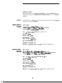
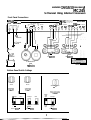
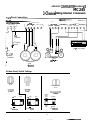
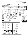
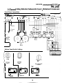
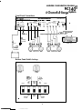
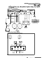
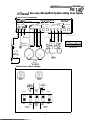
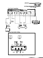
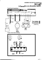
Soundstream MC-140X is a high-performance amplifier with a built-in electronic crossover, offering versatility and exceptional audio quality for various applications. With its 140 watts of power, it can be configured to drive multiple speakers in different setups, including two-channel stereo, three-channel (stereo plus mono), or four-channel (front and rear stereo) configurations. The built-in Staggered Asymmetrical Electronic Crossover provides precise control over the frequency response, allowing you to optimize the sound for your specific speakers and listening preferences.
Soundstream MC-140X is a high-performance amplifier with a built-in electronic crossover, offering versatility and exceptional audio quality for various applications. With its 140 watts of power, it can be configured to drive multiple speakers in different setups, including two-channel stereo, three-channel (stereo plus mono), or four-channel (front and rear stereo) configurations. The built-in Staggered Asymmetrical Electronic Crossover provides precise control over the frequency response, allowing you to optimize the sound for your specific speakers and listening preferences.


-
 1
1
-
 2
2
-
 3
3
-
 4
4
-
 5
5
-
 6
6
-
 7
7
-
 8
8
-
 9
9
-
 10
10
-
 11
11
-
 12
12
-
 13
13
-
 14
14
-
 15
15
-
 16
16
-
 17
17
-
 18
18


Soundstream MC-140X Owner's manual
- Category
- Audio amplifiers
- Type
- Owner's manual
- This manual is also suitable for
Soundstream MC-140X is a high-performance amplifier with a built-in electronic crossover, offering versatility and exceptional audio quality for various applications. With its 140 watts of power, it can be configured to drive multiple speakers in different setups, including two-channel stereo, three-channel (stereo plus mono), or four-channel (front and rear stereo) configurations. The built-in Staggered Asymmetrical Electronic Crossover provides precise control over the frequency response, allowing you to optimize the sound for your specific speakers and listening preferences.
Ask a question and I''ll find the answer in the document
Finding information in a document is now easier with AI
Related papers
-
Soundstream SVX-2 Owner's manual
-
 Soundstream Technologies SA-80 User manual
-
-
 Soundstream Technologies DlOO II User manual
-
-
-
 Soundstream Technologies MC-300 User manual
-
 Soundstream Technologies SSIO User manual
-
-


Other documents
-
Rockford Fosgate PM100X1 Quick Setup
-
 PYLE Audio LA 160 User manual
-
Blaupunkt PCA 250 User manual
-
 Rockford Fosgate Power 360 Installation guide
-
 Soundstream Technologies 404s User manual
-
Hifonics Colossus Pro 5K Owner's manual
-
 Maxxsonics GPV1100.2 User manual
-
Crunch PowerZone PZA Owner's manual
-
-
JL Audio M1000 Owner's manual


