Page is loading ...

UM10534
TEA1723DT GreenChip SP low standby power SMPS demo
board
Rev. 1 — 21 May 2012 User manual
Document information
Info Content
Keywords TEA1723DT, ultra-low standby power, constant output voltage, constant
output current, primary sensing, integrated high-voltage switch, integrated
high-voltage start-up, tablet charger, 5 V/2.1 A supply
Abstract This user manual describes an 11 W Constant Voltage/Constant Current
(CV/CC) universal input power supply for tablet adapters/chargers. This
demo board is based on the GreenChip SP TEA1723DT. GreenChip SP
TEA1723DT enables low no-load power consumption < 40 mW. The
TEA1723DT design ensures a low external component count for
cost-effective applications. In addition, the TEA1723DT provides
advanced control modes for optimal performance. The TEA1723DT
integrates the 700 V power MOSFET switch and SMPS controller.

UM10534 All information provided in this document is subject to legal disclaimers. © NXP B.V. 2012. All rights reserved.
User manual Rev. 1 — 21 May 2012 2 of 23
Contact information
For more information, please visit: http://www.nxp.com
For sales office addresses, please send an email to: [email protected]
NXP Semiconductors
UM10534
TEA1723DT GreenChip SP SMPS demo board
Revision history
Rev Date Description
v.1 20120521 first issue

UM10534 All information provided in this document is subject to legal disclaimers. © NXP B.V. 2012. All rights reserved.
User manual Rev. 1 — 21 May 2012 3 of 23
NXP Semiconductors
UM10534
TEA1723DT GreenChip SP SMPS demo board
1. Introduction
This user manual describes an 11 W Constant Voltage (CV) or Constant Current (CC)
universal input power supply for
tablet adapters and chargers. This demo board is based on
the TEA1723DT GreenChip SP integrated circuit.
The TEA1723DT GreenChip SP provides ultra-low no-load power consumption without
using additional external components. Designs are cost-effective using the TEA1723DT
GreenChip SP because only a few external components are needed in a typical
application. In addition, the TEA1723DT provides advanced control modes for optimal
performance. The TEA1723DT integrates the 700 V power MOSFET switch and SMPS
controller.
Remark: All voltages are in V (AC) unless otherwise stated
2. Safety Warning
The complete demo board application is AC mains voltage powered. Avoid touching the
board when power is applied. An isolated housing is obligatory when used in uncontrolled,
non-laboratory environments. Always provide galvanic isolation of the mains phase using
a variable transformer. The following symbols identify isolated and non-isolated devices.
WARNING
Lethal voltage and fire ignition hazard
The non-insulated high voltages that are present when operating this product, constitute a
risk of electric shock, personal injury, death and/or ignition of fire.
This product is intended for evaluation purposes only. It shall be operated in a designated test
area by personnel qualified according to local requirements and labor laws to work with
non-insulated mains voltages and high-voltage circuits. This product shall never be operated
unattended.
a. Isolated. b. Non-isolated
Fig 1. Isolated and non-isolated symbols
019aab173
019aab174

UM10534 All information provided in this document is subject to legal disclaimers. © NXP B.V. 2012. All rights reserved.
User manual Rev. 1 — 21 May 2012 4 of 23
NXP Semiconductors
UM10534
TEA1723DT GreenChip SP SMPS demo board
3. TEA1723DT features
• Enables low no-load power consumption < 40 mW
• Low component count for a cost-effective design
• Advanced control modes for optimal performance
• SMPS controller with integrated power MOSFET switch
• 700 V high-voltage power switch for global mains operation
• Primary sensing at end-of-conduction for accurate output voltage control
• Avoids audible noise in all operation modes
• Jitter function for reduced EMI
• Energy Star 2.0 compliant
• Universal mains input
• Isolated output
• Highly efficient >78 %
• OverTemperature Protection (OTP)
4. Technical specification
Table 1. Input and output specification
Parameter Condition Value Remark
Input
Input voltage - 90 V to 265 V universal AC mains
Input frequency - 47 Hz to 63 Hz
Average power consumption no-load 33 mW average of 115 V and 230 V
Output
Output voltage - 5 V -
Maximum output current - 2.1 A -
Maximum output power - 11 W -

UM10534 All information provided in this document is subject to legal disclaimers. © NXP B.V. 2012. All rights reserved.
User manual Rev. 1 — 21 May 2012 5 of 23
NXP Semiconductors
UM10534
TEA1723DT GreenChip SP SMPS demo board
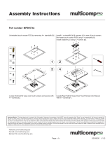
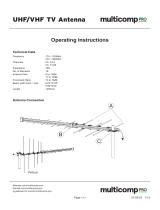
a. Top view.
b. Bottom view.
Fig 2. TEA1723DT 11 W demo board

UM10534 All information provided in this document is subject to legal disclaimers. © NXP B.V. 2012. All rights reserved.
User manual Rev. 1 — 21 May 2012 6 of 23
NXP Semiconductors
UM10534
TEA1723DT GreenChip SP SMPS demo board
5. Performance data
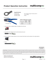
5.1 No-load input power consumption
Test condition: The no-load input power is measured after a 20 minute warm-up time.
5.2 Output voltage and efficiency
Test condition: The efficiency and VI power characteristics are measured after a
20 minute warm-up time.
Table 3
, Figure 4 and Figure 5 show the efficiency figures and VI characteristics
measured of the GreenChip SP TEA1723DT demo board.
Table 2. No-load input power consumption
Condition Output voltage Power consumption
115 V at 60 Hz 5 V 31.7 mW
230 V at 50 Hz 5 V 34.7 mW
Fig 3. No-load input power consumption
,QSXW9ROWDJH9
DDD
1RORDGSRZHU
P:
Table 3. Efficiency and VI characteristics at 115 V and 230 V
V
CC
Parameter Values
115 V I
out
(A) 0 0.04 0.1 0.2 0.4 0.6 0.8 1 1.2 1.4 1.6 1.8 2 2.1
V
out
(V) 5.09 5.06 5.03 4.98 4.96 4.97 4.97 4.99 5.01 5.03 5.04 5.06 5.08 4.97
P (W) 0.023 0.37 0.74 1.35 2.54 3.83 5.09 6.42 7.72 9.04 10.4 11.7 13.1 13.5
(%) 54.7 68 73.8 78.1 77.9 78.1 77.7 77.9 77.9 77.7 77.6 77.6 77.4
230 V I
out
(A) 0 0.04 0.1 0.2 0.4 0.6 0.8 1 1.2 1.4 1.6 1.8 2 2.1
V
out
(V) 5.06 5.04 5.03 4.97 4.96 4.96 4.96 4.99 5.01 5.02 5.04 5.05 5.07 5.08
P (W) 0.0256 0.41 0.84 1.43 2.63 3.82 5.04 6.33 7.6 8.86 10.1 11.4 12.7 13.4
(%) 49.2 59.9 69.5 75.4 77.9 78.7 78.8 79.1 79.3 79.6 79.6 79.7 79.8

UM10534 All information provided in this document is subject to legal disclaimers. © NXP B.V. 2012. All rights reserved.
User manual Rev. 1 — 21 May 2012 7 of 23
NXP Semiconductors
UM10534
TEA1723DT GreenChip SP SMPS demo board
5.3 Dynamic loading from 0 A to 0.5 A
Test condition: The dynamic loading is tested at a load step of 0 A to 0.5 A. The
TEA1723DT detects the load step only after the next switching cycle because of the
primary sensing feature.
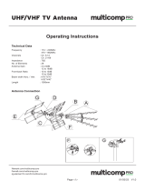
(1) 90 V.
(2) 115 V.
(3) 230 V.
(4) 265 V.
Fig 4. VI characteristics at 90 V, 115 V, 230 V and 265 V
(1) Efficiency at 115 V.
(2) Efficiency at 230 V.
Fig 5. Efficiency at 115 V and 230 V
O
RXW
$
DDD
9
RXW
9
O
RXW
$
DDD
Ș

UM10534 All information provided in this document is subject to legal disclaimers. © NXP B.V. 2012. All rights reserved.
User manual Rev. 1 — 21 May 2012 8 of 23
NXP Semiconductors
UM10534
TEA1723DT GreenChip SP SMPS demo board
The load step is measured at V
mains
= 230 V and the output capacitor C5 value is 680 F.
The burst frequency is 1270 Hz.
5.4 Dynamic loading from 0.5 A to 0 A
Test condition: The dynamic loading is tested at a load step of 0 A to 0.5 A. The
TEA1723DT detects the load step only after the next switching cycle because of the
primary sensing feature.
The load step is measured at V
mains
= 230 V and the output capacitor C5 value is 680 F.
(1) CH1 = V
DRAIN
.
(2) CH2 = I
O
.
(3) CH3 = V
O
.
Fig 6. Load step from 0 A to 0.5 A

UM10534 All information provided in this document is subject to legal disclaimers. © NXP B.V. 2012. All rights reserved.
User manual Rev. 1 — 21 May 2012 9 of 23
NXP Semiconductors
UM10534
TEA1723DT GreenChip SP SMPS demo board
After the load step 0.5 A to 0 A, the output voltage rises to 5.1 V. The transition takes
about 1 ms when the controller switches from CV to CVB because of the large electrolytic
output capacitor C5 (680 F).
5.5 Short-circuit of the output
The demo board output can be short-circuited without damaging of any component.
Test condition: Figure 7
shows the converter behavior when the output is short circuited.
During a short-circuit of the output, the VCC voltage (CH3) switches between
V
CC(startup)
= 17 V and V
CC(stop)
= 8.5 V levels. The average output current during
converter switching is 1.2 A.
(1) CH1 = V
DRAIN
.
(2) CH2 = I
O
.
(3) CH3 = V
O
.
Fig 7. Load step from 0.5 A to 0 A

UM10534 All information provided in this document is subject to legal disclaimers. © NXP B.V. 2012. All rights reserved.
User manual Rev. 1 — 21 May 2012 10 of 23
NXP Semiconductors
UM10534
TEA1723DT GreenChip SP SMPS demo board
5.6 Output voltage ripple performance
Test condition: Output voltage ripple is measured using an oscilloscope probe connected
to the demo board output. A probe tip was used with a very small GND connection. A
100 nF capacitor between output voltage and GND is used to reduce high frequency
noise. The output voltage ripple was measured at full load and at V
mains
= 230 V.
Figure 8
shows the output voltage ripple at 2.1 A load at 230 V. Using output capacitor C5
680 F, the output ripple voltage is 205 mV.
(1) CH1 = V
DRAIN
.
(2) CH2 = V
CC
.
(3) CH3 = I
O
.
(4) CH4 = V
O
.
Fig 8. Short-circuit of the output

UM10534 All information provided in this document is subject to legal disclaimers. © NXP B.V. 2012. All rights reserved.
User manual Rev. 1 — 21 May 2012 11 of 23
NXP Semiconductors
UM10534
TEA1723DT GreenChip SP SMPS demo board
5.7 Conducted EMI measurement results
The EMI is measured with the secondary GND connected to the protected mains earth
GND. Y-capacitor (C10 = 2.2 nF; 2 kV) is added and only one input coil L1 = 1.5 mH is
used. EMI is measured on the neutral phase and on the line phase at V
mains
= 230 V and
at full load. The frequency range is 150 kHz to 30 MHz.
Remark: Improved transformer design will enhance TEA1723DT EMI performance
significantly.
(1) CH1 = V
DRAIN
.
(2) CH4 = V
O
on board. Scale = 100 mV/division.
Fig 9. Output voltage ripple

UM10534 All information provided in this document is subject to legal disclaimers. © NXP B.V. 2012. All rights reserved.
User manual Rev. 1 — 21 May 2012 12 of 23
NXP Semiconductors
UM10534
TEA1723DT GreenChip SP SMPS demo board
Remark: Improved transformer design will enhance TEA1723DT EMI performance significantly.
Fig 10. Line 230 V, full load and negative output connected to protected earth
Remark: Improved transformer design will enhance TEA1723DT EMI performance significantly.
Fig 11. Neutral 115 V, full load and negative output connected to protected earth

UM10534 All information provided in this document is subject to legal disclaimers. © NXP B.V. 2012. All rights reserved.
User manual Rev. 1 — 21 May 2012 13 of 23
NXP Semiconductors
UM10534
TEA1723DT GreenChip SP SMPS demo board
Remark: Improved transformer design will enhance TEA1723DT EMI performance significantly.
Fig 12. Line 115 V, full load and negative output connected to protected earth
Remark: Improved transformer design will enhance TEA1723DT EMI performance significantly.
Fig 13. Neutral 230 V, full load and negative output connected to protected earth

UM10534 All information provided in this document is subject to legal disclaimers. © NXP B.V. 2012. All rights reserved.
User manual Rev. 1 — 21 May 2012 14 of 23
NXP Semiconductors
UM10534
TEA1723DT GreenChip SP SMPS demo board
6. Schematic and Bill Of Materials (BOM)
6.1 TEA1723DT 11 W demo board schematic
6.2 Bill of Materials
Fig 14. TEA1723DT 11 W demo board schematic
DDD
)%
&
S)
9
&
Q)
9
&
)
9
5
ȍ
'
30///
*1'
*1'
*1'
9&&
6285&(
7($'7
'5$,1
,&
7
7UDQVIRUPHU
:XUWK
:
&
Q)
N9
&
S)
9
&
)
9
'
1
N9
5
VHQVH
ȍ
5
)%
Nȍ
5
)%
Nȍ
&
)
9
5
Nȍ
5
ȍ
5
Nȍ
/
P+
5)
-
-
1
/
ȍ
'
1
N9
'
1
N9
'
1
N9
'
1
N9
9$&WR
9$&
5
ȍ
&
&
)
9
&
)
9
Q)
9
'
6%5863
$
9
5
Nȍ
-
9
Table 4. Bill of materials
Part Description Part Number Manufacturer
C1 capacitor; 10 F; 400 V; 10 mm 16 mm EKMQ401ELL100MJ16S Chemi-Con
C2 capacitor; 10 F; 400 V; 10 mm 16 mm EKMQ401ELL100MJ16S Chemi-Con
C3 capacitor; 10 F; 50 V; 5 mm 11 mm ECA1HHG100 Panasonic
C4 capacitor; 2.2 nF; 50 V; 0805 C0805C222K5RACTU KEMET
C5 capacitor; 680 F; 10 V; 8 mm 11.5 mm UHM1A681MPD Nichicon
C6 not mounted - -
C7 capacitor; 10 pF; 0805 - -
C8 capacitor; 10 nF; 0805 X7R -
C9 not mounted - -
C10 capacitor; 2.2 nF; 2 kV DEBB33D222KA2B Murata
C11 capacitor; 470 pF; 500 V; 0805 CC0805JRNPOBBN471 Yageo
C12 capacitor; 22 F; 10 V; 1206 GRM31CR71A226KE15L Murata
D1 diode; 1N4007; 1 kV; DO-41; 1 A 1N4007 Multicomp
D2 diode; 1N4007; 1 kV; DO-41; 1 A 1N4007 Multicomp
D3 diode; 1N4007; 1 kV; DO-41; 1 A 1N4007 Multicomp
D4 diode; 1N4007; 1 kV; DO-41; 1 A 1N4007 Multicomp
D5 diode; 1N4007; 1 kV; DO-41; 1 A 1N4007 Vishay
D7 diode; PMLL4148; SOD80C glass PMLL4148L NXP Semiconductors

UM10534 All information provided in this document is subject to legal disclaimers. © NXP B.V. 2012. All rights reserved.
User manual Rev. 1 — 21 May 2012 15 of 23
NXP Semiconductors
UM10534
TEA1723DT GreenChip SP SMPS demo board
D8 diode; SBR10U45SP5; 45 V; PowerDI5; 10 A SBR10U45SP5-13 Diodes Inc
IC1 controller; TEA1723DT; S07 TEA1723DT NXP Semiconductors
L1 inductor; 1.5 mH; DIP - Murata
R1 resistor; 10 k; 1206 - -
R3 resistor; 100 k; 1206 - -
R4 resistor; 180 ; 1206 - -
R5 resistor; 2.4 ; 1206 - -
R6 resistor; 12 ; 0805 - -
R7 resistor; 5.6 k; 0805 - -
R8 resistor; 39 k; 0805 - -
R9 resistor; 33 ; 0805 - -
R10 resistor; 1.5 k; 0805 - -
R11 resistor; 2.4 ; 1206 - -
R12 resistor; 2.2 ; 1206 - -
R13 resistor; 39 k; 0805 - -
R14 resistor; 200 k; 0805 - -
RF1 fused resistor; 10 ; 3 W; ULW310RJA1 Welwyn Components
T1 transformer; 0.9 mH; EE20/10/6 horizontal - Würth Elektronik
W1 jumper wire; DIP - -
Table 4. Bill of materials
…continued
Part Description Part Number Manufacturer

UM10534 All information provided in this document is subject to legal disclaimers. © NXP B.V. 2012. All rights reserved.
User manual Rev. 1 — 21 May 2012 16 of 23
NXP Semiconductors
UM10534
TEA1723DT GreenChip SP SMPS demo board
7. Circuit description
The TEA1723DT GreenChip SP demo board consists of a single-phase full-wave rectifier
circuit with sections for filtering, switching, output and feedback. The circuit diagram is
shown in Figure 14 on page 14
and the component list is shown in Table 4 on page 14.
7.1 Rectification section
The bridge diodes BD1 form the single-phase full-wave rectifier. Capacitors C1 and C2
are reservoir capacitors for the rectified input voltage. Resistor RF1 limits inrush current
and acts as a fuse. Terminals 1 and 2 connect the input to the AC mains network.
Swapping these two wires has no effect on the operation of the converter.
7.2 Filtering section
Inductors L1 and L2 in combination with capacitors C1 and C2, form -filters to attenuate
the conducted differential mode EMI noise.
7.3 GreenChip SP section
The TEA1723DT device IC1 contains the power MOSFET switch, oscillator, CV/CC
control, start-up control and protection functions. Its integrated 700 V MOSFET allows
sufficient voltage margins for universal input AC applications, including line surges.
The auxiliary winding on transformer T1 generates the supply voltage and primary
sensing information for the TEA1723DT. Diode D7 and capacitor C3 half-wave rectified
the voltage. C3 is charged using the current limiter resistor R6. The voltage on C3 is the
supply voltage for the VCC pin.
RCD-R clamp (which consists of R4, C9, D5 and R3) limits drain voltage spikes caused by
any leakage inductance from the transformer.
7.4 Output section
Diode D7 is a Schottky barrier type diode and capacitors C5/C6 rectify the voltage from
secondary winding of transformer T1. Using a Schottky diode results in higher efficiency of
the demo board.
C5 and C6 must have a sufficiently low ESR to meet the output voltage ripple requirement
without adding an LC post filter.
Resistor R9 and capacitor C4 dampen the high frequency ringing and reduce the voltage
stress on diode D8. Resistor R10 provides a minimum load to maintain output control in
the no-load condition.
7.5 Feedback section
The TEA1723DT controls the output using current and frequency control for CV/CC
regulation. The auxiliary winding on Transformer T1 senses the output voltage. The FB
pin senses the reflected output voltage using feedback resistors R
FB1
and R
FB2
.

UM10534 All information provided in this document is subject to legal disclaimers. © NXP B.V. 2012. All rights reserved.
User manual Rev. 1 — 21 May 2012 17 of 23
NXP Semiconductors
UM10534
TEA1723DT GreenChip SP SMPS demo board
8. PCB layout
Figure 16 shows the layout of the PCB.
a. Top silk b. Bottom silk
c. Bottom layer
Fig 15. Board layout

UM10534 All information provided in this document is subject to legal disclaimers. © NXP B.V. 2012. All rights reserved.
User manual Rev. 1 — 21 May 2012 18 of 23
NXP Semiconductors
UM10534
TEA1723DT GreenChip SP SMPS demo board
9. Transformer specifications
9.1 Transformer schematic design and winding construction
The transformer used in the TEA1723DT demo board has size EE20 with bobbin
EE20/10/6 horizontal, 14-pin. The secondary side of the transformer is connected in
parallel in the TEA1723DT demo board, see Figure 16
.
• Würth-Midcom 760871112
9.2 Electrical characteristics
Fig 16. Transformer schematic design
PD[
:(
315HY[[
<<::
PDUNLQJSLQ
UHYLVLRQFRGH
PD[
PD[
DDD
17V3PP
VSUHDGRYHUIXOOOD\HU
PP PP
OD\HUWDSH
OD\HUWDSH
OD\HUWDSH
OD\HUWDSH
17V3PP
OD\HUV=ZLQGLQJZLWKOD\HULQVXODWLRQ
61&7V3PP
OD\HU
17V3PP7,:
VSUHDGRYHUIXOOOD\HU
1
9
1
9$
1
9
$
6
QF
Table 5. Electrical characteristics
Description Pin Specifications Comments
Primary inductance 1 to 3 0.9 mH 10 % -
Leakage 1 to 3 50 µH secondary side short-circuited

UM10534 All information provided in this document is subject to legal disclaimers. © NXP B.V. 2012. All rights reserved.
User manual Rev. 1 — 21 May 2012 19 of 23
NXP Semiconductors
UM10534
TEA1723DT GreenChip SP SMPS demo board
9.3 Core, air gap and bobbin
• Core: EE20/10/6 (3C90)
• Size of the air gap depends on the A
L
value of the ungapped core.
• Bobbin: EE20/10/6 horizontal, 14-pin
Fig 17. EE20/10/6 bobbin footprint
DDD

UM10534 All information provided in this document is subject to legal disclaimers. © NXP B.V. 2012. All rights reserved.
User manual Rev. 1 — 21 May 2012 20 of 23
NXP Semiconductors
UM10534
TEA1723DT GreenChip SP SMPS demo board
10. Attention points
When testing the CC mode of the TEA1723DT, use an electronic DC-load in resistive
mode, not in current mode.
The current in CC mode has a small fold back characteristic (see Figure 4
). When current
mode of an electronic DC-load is used, the output voltage drops immediately to zero when
the maximum current is exceeded. Once the output voltage and the input voltage of the
DC-load is zero, many DC-loads cannot adjust the current. Using the resistive mode of the
electronic DC-load avoids this problem.
Remark: This TEA1723DT controller behavior is not incorrect. Only test it in the correct
way.
/