Page is loading ...

April
1979
FORM:
OM1517
Effective
With
Serial
No.
HJ213624
MODEL
SWINGARC
DUAL
12
SWINGARC
DUAL
16
OWN
E
RS
MANUAL
hullER
1.,
MILLER
ELECTRIC
MFG.
CO.
718
S.
BOUNDS
ST.
P.O.
Box
1079
APPLETON,
WI
54912
USA
ADDITIONAL
COPY
PRICE
75
CENTS
NWSA
CODE
NO. 4579
PRINTED
IN
U.S.A.

b~
LIMITED
WARRANTY
EFFECTIVE:
JANUARY
1,
1979
This
warranty
supersedes
all
previous
MILLER
warranties
and
is
ex
clusive
with
no
other
guarantees
or
warranties
expressed
or
implied.
.
LIMITED
WARRANTYSubject
to
the
terms
and
conditions
As
a
matter
of
general
policy
only,
Miller
may
honor
claims
hereof,
Miller
Electric
Mfg.
Co.,
Appleton,
Wisconsin
warrants
to
submitted
by
the
original
user
within
the
foregoing
periods.
its
Distributor/Dealer
that
all
new
and
unused
Equipment
furnished
~
by
Miller
is
free
from
defect
in
workmanship
and
material
as
of
the
In
the
case
of
Millers
breach
of
warranty
or
any
other
duty
time
and
place
of
delivery
by
Miller.
No
warranty
is
made
by
Miller
with
respect
to
the
quality
of
any
goods,
the
exclusive
remedies
with
respect
to
engines,
trade
accessories
or
other
items
manu-
therefor
shall
be,
at
Millers
option,
(I)
repair
or
(2)
replacement
or,
factured
by
others.
Such
engines,
trade
accessories
and
other
where
authorized
in
writing
by
Miller
in
appropriate
cases,
(3)
the
items
are
sold
subject
to
the
warranties
of
their
respective
manu-
reasonable
Cost
of
repair
or
replacement
at
an
authorized
Miller
ser
facturers,
if
any.
At
the
present
time,
the
manufacturers
warranty
on
VICC
Station
or
(4)
payment
of
or
credit
for
the
purchase
price
(less
the
Mag-Diesel
engine
on
DEL-200
is
limited
to
six
months
and
on
reasonable
depreciation
based
upon
actual
use)
upon
return
of
the
all
other
engines
to
one
year.
goods
at
Customers
risk
and
expense.
Upon
receipt
of
notice
of
apparent
defect
or
failure,
Miller
shall
instruct
the
claimant
on
the
Except
as
specified
below,
Millers
warranty
does
not
apply
to
warranty
claim
procedures
to
be
followed.
components
having
normal
useful
life
of
less
than
one
(1)
year,
such
ANY
EXPRESS
WARRANTY
NOT
PROVIDED
HEREIN
AND
as
spot
welder
tips,
relay
and
contactor
points,MILLERMATIC
parts
ANY
IMPLIED
WARRANTY
GUARANTY
OR
REPRESENTA
~
that
come
in
contact
with
the
welding
wire
including
nozzles
and
lION
AS
TO
PERFORMANCE,
AND ANY
REMEDY
FOR
nozzle
insulators
where
failure
does
not
result
from
defect
in
BREACH
OF
CONTRACT
WHICH,
BUT
FOR
THIS
PROVISION,
workmanship
or
material.
MIGHT
ARISE
BY
IMPLICATION,
OPERATION
OF
LAW,
CUS
TOM
OF
TRADE
OR
COURSE
OF
DEALING
INCLUDING
ANY
Miller
shall
be
required
to
honor
warranty
claims
on
warranted
IMPLIED
WARRANTY
OF
MERCHANTABILITY
OR
OF
FITNESS
Equipment
in
the
event
of
failure
resulting
from
a
defect
within
the
FOR
PARTICULAR
PURPOSE,
WITH
RESPECT
TO
ANY
AND
following
periods
from
the
date
of
delivery
of
Equipment
to
the
.
ALL
EQUIPMENT
FURNISHED
BY
MILLER
IS
EXCLUDED
)
original
user:
AND
DISCLAIMED
BY
MILLER.
I.
Arc
welders,
power
sources
and
components
- .
.
-
1
year
EXCEPT
AS
EXJRESSLY
PROVIDED
BY
MILLER
IN
WRIT-
)
2.
Original
main
power
rectifiers
3
years
ING
MILLER
PRODUCTS
ARE
INTENDED
FOR
ULTIMATE
(labor
-
1
year
only)
PURCHASE
BY
COMMERCIAL/INDUSTRIAL
USERS
AND
FOR
3.
A1Iweldsnggunsandfeeder(g~ais
90days
OPERATION
BY
PERSONS
TRAINED
AND
EXPERIENCED
IN
4.
All
other
Millermatic
Feeders
1
year
THE
USE
AND
MAINTENANCE
OF
WELDING
EQUIPMENT
AND
5.
Replacement
or
repair
parts,
exclusive
of
labor
:
.
-
60
days
NOT
FOR
CONSUMERS
OR
CONSUMER
USE.
MILLER
WAR-
6.
Batteries
6
months
RANTIES
DO
NOT
EXTEND
TO,
AND
NO
RESELLER
IS
provided
that
Miller
is
notified
in
writing
within
thirty
(30)
days
of
AUTHORIZED
TO
EXTEND
MILLERS
WARRANTIES
TO,
the
date
of
such
failure.
ANY
CONSUMER.
..
,,
~
-...-,~,
J~
--.
~1,
.....
-.....
.

ERRATA
SHEET
After
this
manual
was
printed,
refinements
in
equipment
design
occurred.
This
sheet
lists
exceptions
to
data
appearing
later
in
this
manual.
AMENDMENT
TO
SECTION
2
INSTALLATION
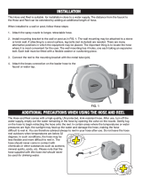
Amend
Section
2-6C.
Inlet
Wire
Guide
I~.1l~
An
extension
liner
(082
050)
and
inlet
wire
guide
(082
036)
are
provided
with
mode/s
effective
with
Serial
No.
JA420762
for
use
with
small
diameter
wire.
The
liner
will
handle
wire
up
to
5/64
diameter.
1.
For
.030-5/64
wire.
a.
Insert
liner
(082
050)
into
inlet
w
guide
(082
036)
and
secure
with
set
screw.
b~
Loosen
the
inlet
wire
guide
securing
screw
(
I~1IsTt~
Wire
guides
should
be
installed
so
that
the
tip
of
the
guide
is
as
close
to
the
drive
roll
as
possible
without
touching.
c.
Insert
guide
assembly
into
drive
assembly.
Secure
by
tightening
screw
(3).
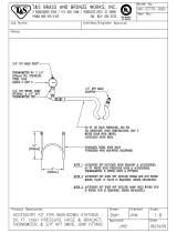
2.
For
3/32-l
/8
wire.
a.
Remove
anti-wear
guide(s)
(045
233)
from
inlet
wire
guide.
b.
Loosen
the
inlet
wire
guide
securing
screw
(3).
I~Is~I~
Wfre
guides
should
be
installed
so
that
the
tip
of
the
guide
is
as
close
to
the
drive
roll
as
possible
without
touching.
c.
Insert
tt~e
inlet
wire
guide
(1)
into
drive
assembly
as
illustrated
in
Figure
2-4.
Secure
by
tightening
screw
(3).
d.
Install
anti-wear
guide(s)
onto
inlet
wire
guide
and
secure
with
set
screw.
I~Isfl~
Behind
the
drive
gear
is
a
spring
washer(s).
To
obtain
proper
alignment
of
the
drive
roll
on
the
drive
gear
with
the
wire
guides
rotate
the
drive
gear
securing
bolt
(11)
thereby
moving
the
drive
roll
in
or
out
to
the
desired
posi
tion.
The
drive
roll
on
the
pressure
gear
will
locate
itself
on
the
wire
when
the
gear
cover
is
rep/aced
and
the
gears
mesh
together.
Amend
Section
2-7.
WATER
CONTROL
KIT
Add
IMPORTANT
block
at
beginning
of
Section.
If
a
recirculating
coolant
system
is
used,
do
not
make
connections
from
the
coolant
pump
to
the
Water
valve
but
rather
connect
directly
to
the
gun
water
hoses.
Failure
to
comply
may
result
in
damage
to
the
coolant
pump
and/or
gun.
Amend
SectiOn~
2~8D.
Switch
Control
Two
four-contact
receptacles
extend
out
of
the
motor
end
of
the
boom
for
connecting
the
gun
switch
plugs
to
the
control.
Connect
the
Left
Gunto
the
gun
switch
receptacle
labeled
LEFT
TRIGGER,
and
the
Right
Gun
to
the
other
gun
switch
receptacle
by
inserting
the
plugs
fully
into
the
receptacles
and
rotating
the
locking
rings.
When
one
welding
power
source
is
utilized,
both
electrode
wires
will
be
electrically
energized
when
either
gun
switch
is
closed.
Amend
Section
2-14.
CONTACTOR
CONTROL
CONNECTIONS
(Figure
2-8)
______________
The
contactor
control
circuitry
that
is
to
be
used
in
conjunction
with
this
control/feeder
must
be
of
the
type
that
operates
on
115
volts
60
Hertz
power.
This
is
necessary
because
the
control
will
supply
115
volts
ac
through
the
contactor
control
cable
whenever
the
gun
switch
is
closed.
IMPORTANT
CAUTION
IMPORTANT
OM-1517
Page
A

A.
Using
One
Welding
Power
Source
1
The
contactor
control
circuitry
in
this
control/feeder
is
connected
to
operate
both
guns
from
one
welding
power
source.
Insert
the
plug
on
one
contactor
control
cable
fully
into
the
Left
Contactor
Control
receptacle
and
rotate
the
plug
clockwise.
Connect
the
remaining
end
of
the
contactor
control
cable
to
the
contact~
control
receptacle
on
the
welding
power
source.
Store
the
remaining
contactor
control
cable.
CAUTION
Both
electrode
wires
will
be
electrically
energized
when
either
gun
switch
is
closed;
B.
Using
Two
Welding
Power
Sources
Through
minor
modification,
the
contactor
control
circuitry
of
the
control/feeder
can
be
adapted
to
operate
two
welding
power
sources,
that
is,
the
left
gun
switch
governing
contactor
control
to
one
welding
power
source
and
the
right
gun
switch
governing
contactor
control
to
the
other.
Two
contactor
control
cables
are
supplied
with
the
unit
for
making
connections
to
the
contactor
control
circuitries
in
the
welding
power
sources.
CAUTION
__________
Placing
the
POWER
switch
in
the
OFF
position
does
not
remove
power
from
all
of
the
controls
internal
circuitry.
Completely
terminate
all
electrical
power
to
the
control
by
removing
the
115
volts
ac
plug
from
its
power
supply,
and
ensure
that
machinery
lockout
procedures
have
been
employed
on
the
welding
power
sources
input
line
(see
Instruction
Manual
on
welding
power
source)
before
attempting
any
inspection
or
work
inside
the
unit.
1.
Remove
the
wrapper
from
the
control
box
on
the
control/feeder
2..
Locate
terminal
strip
IT
on
the
bottom
panel
of
the
control.
3.
Disconnect
lead
No.
39
from
terminal
A
on
terminal
strip
iT
and
reconnect
it
to
terminal
B.
4.
Replace
wrapper.
5..
Insert
the
plug
on
the
contactor
control
cable
fully
into
the
Left
Contactor
Control
receptacle
and
rotate
the
plug
clockwise;
connect
the
remaining
end
of
the
cable
to
the
contactor
control
circuitry
in
the
appropriate
welding
power
source.
Insert
the
plug
on
the other
contactor
control
cable
fully
into
the
Right
Contactor
Control.
recep
tacle
and.
rotate
the
plug~clockwise;
connectthe
remaining
end
of
the
cable
to
the
contactor
control
circuitry
in
the
other
welding
power
source~
~
-~
~
-..~.-.,.
~
~
-
~-~
.~
-
-.
-.
-~.~---
~
OM-1517
Page
B

o~
-J -u
as
as
C)
F
CRS!.
RIGHT
p~O12
3
3
-1-
~
162
~j
I
I
L
J
~
Ce
Tt
32
3,
RIGHT
INCH
SW
~~~Tl4
I
/
VI
I
CR
CR1
CAs
a
Z
0
C
m
~
2
C)
-~
-I
Li
-I
0
C
ii
Cl)
x
00
-.4
2
C)
IISV
AC
3/
I~IPLGR
DII
VE
RI
A
PIG?
PC?
CR0.
SILVER
4
PURGE-LEFT
SIDE
CR1
~
~
CR9
6
CR2
TOR~~
1
LEFTp~2
?
~
DC
,0
18
a
~47
a
148
45
R
I
R
L_~J
~
RC3
PIGS
PLGI2
lIST,
FOR
111111
______-~<_~-<
CONTACIOR
-
LEFT
SIDE
SILVER
CS1
GAS
ILEFT
SIDE
SOLENOID
___
WATER
I
L.<2<
~OLENOIGJ
-<1<
OPTIONAL
ESTRA
PLGH
Caa~
PURGE-RIGHT
SIDE
L~
60
PART
OF
LEFT
RURNOACK
PART
OF
RIGHT
BURN8HCK
HLGI4
PLG2
RCZ
2>WfiT
~
1.
>
WIDE
SLOT
TRIGGER
LEFT
SIDE
PLG,5
WI8113
I
RCa
PIGR
~
~
~
I1SV
FOR
C
ON
T
V
CTOR
RIGHT
SIDE
I
SILVER
CS
GAS
<4<
RIGHT
SIDE
L<
2<
<1<
RC1O
PLCIO
*
OPTIONAL
aCts
RMT
-
A>
8>
STD.
RIGHT
C>-~-
REMOTE
F>
2
HC8
SlIT.
_!~_
0
CRs
I
<-C
40
HI
I
I
LEFT
~
J~h~~R1C.3
:
03
I
REMOTE
0>
1SPEED
4~
<<I
I
>*
L((
I
F>
J
~
C~
LI
08
54f*21f
T
<<
-
I
f~1
j
*CRV
I
I
I
CI
RT
~
I
~
C3
22
__
1
I
~-,
a
I
~
C,~
2
~
I
I
/L~
H
I
I
I
0
H
I
1
aJ
04
]%C9
I
I
/~~J
LjJ
I
i
D~
9
~I
I
23
02
05
I
1
2
0
(I
181
HIGVT
c~2
D~
ri
WIRE
I
194
SPEED
.L
A
Cm
02
I
I
C7rn
________
A
]
I
Ct~
I
F
I
<~
_I_
I
1f-T1.
I
I
t1YI
I
CO1
~13
I
29
1
I
~I
___________________________________________________
III
I
4A2
<
&
I
A4~
41.APLGI
Fl
I
~.
HCSL
CI~U~!O~R~
rU1
I
K~)~CW
-
I
WIRE
DRIVE
I
L
~
Circuit
Diagram
No.
C-047
894
I9VT
aLE
__________
WIDE
SLOT
CR1
~
j
TRIGGER
RIGHT
SIDE
69
38
3?
59
1835
22
10
72
33
65
34
4
1
o
q
p
0
q
p
e
0
q
p
q
p
0
0
IT
A
ot
0
E
F
CII
2
IlL
UN
P
391
nO
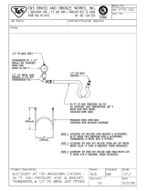
figure
6-1.
Circuit
Diagram
for
Models
Effective
With
Serial
No.
HK300259

Quantity
Models
Item
Dia.
Part
Replaced
No.
Mkgs.
No.
With
Description
12
16
12
073 839
056
112
FITTING,
hose
-
ferrule
0.475
1D
x
23/32
6
6
27
073
839
056
112
FITTING,
hose-ferrule
0.475
ID
x23/32
2
2
34
604
525
604
525
CORD,
portable
(order
by
ft)
(qty
chg)
16
ft
20
ft
110
RC3,9
039
885
039
602
RECEPTACLE,
twistlock2P2W2O
amp
250
volts
2
2
145
R15
030
853
028
276
RESISTOR,carbon0.5watt2200
ohm
1
1
Pg
7
C2,3
031
694
044
602
CAPACITOR,
poly
film
0.47
uf
400
volts
dc
2
2
180
079029
079029
NUT(qtychg)
1
605
884
NUT,
hex
-
half
3/4-16
1
186
073
664
024
605
BEARING,
ball
1
194
073695
047224
KNOB,Tbar
1
1
048 336
STOP,
cover
2
2
010
193
TUBING,steel3/8ODxl8gawalIxl/4
2
2
045
233
GUIDE,
anti-wear
1 1
604
612
.
SCREW,
set-
socket
hd8-32
x
1/8
1
1
082
036
GUIDE,
inlet
-
wire
(Eff
w/JA420762)
2 2
082
050
LINER,
monocoil
-
inlet
wire
(Effw/JA420762)
2
2
604
612
SCREW,
set-sockethd8-32x
1/8
(Effw/JA420762)
2 2
051
297
ADAPTER
(add
to
itemS)
1
1
047
171
LINER,monocoilxl3
1
1
023
562
CLAMP,
hose
5/16-7/8
clamp
dia
1
1
602
204
WASHER,
lock
-
external
tooth
No.
10
1
1
BE
SURE
TO
PROVIDE
MODEL
AND
SERIAL
NUMBERS
WHEN
ORDERING
REPLACEMENT
PARTS.
OM-1517
Page
D

TABLE
OF
CONTENTS
Section
No.
Page
No.
SECTION
1
INTRODUCTION
1-1.
General
1
1
-
2.
Receiving-Handling
1
1
-
3.
Description
1
1-4.
Safety
1
SECTION
2
INSTALLATION
2
-
1.
Location
And
Assembly
1
2
-
2.
Drive
Motor
3
2
-
3.
Installation
of
Wire
Support
3
2
-
4.
Reinstallation
of
Hub
Assembly
3
2
-
5.
Installation
of
Wire
Reel
3
2
-
6.
Drive
Roll
and
Wire
Guide
Installation
3
2
-
7.
Water
Control
Kit
Connections
4
2
-
8.
Welding
Gun
Connections
5
2
-
9.
Shielding
Gas
Connections
5
2-10.
Boom
Adjustments
6
2-11.
Motor
Control
Connection
6
2-12.
Switch
Control
Connections
6
2-13.
Weld
Cable
Connection
6
2-14.
Contactor
Control
Connections
6
2-15.
115
Volts
AC
Connections
7
2-16.
Installation
of
Spool-Type
Wire
7
2-17.
Installation
of
Reel-Type
Wire
7
2-18.
Adjustment
of
Hub
Tension
7
2-19.
Welding
Wire
Threading
7
SECTION
3
FUNCTION
OF
CONTROLS
3
-
1.
Power
Switch
8
3
-
2.
Wire
Speed
Controls
8
3
-
3.
Remote
Control
Receptacles
and
Switches
8
3-4.
Purge
Buttons
8
3
-
5.
Inch
Switches
8
3
-
6.
Reset
Circuit
Breaker
8
3-
7.
Burnback
Controls
8
SECTION
4
SEQUENCE
OF
OPERATION
4
-
1.
Gas
Metal-Arc
Welding
(GMAW)
9
4
-
2.
Shutting
Down
9
SECTION
5MAINTENANCE
5-
1.
Inspection
and
Upkeep
9
5
-
2.
Cleaning
of
Drive
Rolls
9
SECTION
6
TROUBLESHOOTING
PARTS
LIST


SECTION
1
-
INTRODUCTION
Model
Dual 12
Dual
16
Speed
Range
70-750
I.P.M.
Boom
Length
12
ft.
I
16
ft.
Swing
360
Vertical
Lift
Horizontal
To
600
Above
Maximum
Height
(With
4
Ft
Post)
At_Full_Lift_Of_Boom
17
ft.
21
ft.
.
Counterbalance
(Patented)
Compression
Spring
Is
Designed
To
Bal
ance
Boom
At
Any
Angle.
Pressure
Ad~ustment
Is
Provided
To
Hold
The
Boom
At
Any
Desired
Angle
Or
To
Limit
The
Vertical
Lift
At
40,
500,
or
60.
Weight
(Pounds)
Net
Ship
I
Net
Ship
205
325
j
290
410
Figure
1-1.
Specifications
1-1.
GENERAL
This
manual
has
been
prepared
especially
for
use
in
familiar
izing
personnel
with
the
design,
installation,
operation,
main
tenance,
and
troubleshooting
of
this
equipment.
All
informa
tion
presented
herein
should
be
given
careful
consideration
to
assure
optimum
performance
of
this
equipment.
1
-2.
RECEIVING-HANDLING
Prior
to
installing
this
equipment,
clean
all
packing
material
from
around
the
unit
and
carefully
inspect
for
any
damage
that
may
have
occurred
during
shipment.
Any
claims
for
loss
or
damage
that
may
have
occurred
in
transit
must
be
filed
by
the
purchaser
with
the
carrier.
A
copy
of
the
bill
of
lading
and
freight
bill
will
be
furnished
by
the
carrier
on
request
if
occasion
to
file
claim
arises.
When
requesting
information
concerning
this
equipment,
it
is
essential
that
Model
Description
and/or
Stock
Number
and
Serial
(or
Style)
Numbers
of
the
equipment
be
supplied.
1
-
3.
DESCRIPTION
This
unit
is
a
boom
mounted
wire
control/feeder.
The
control/feeder
is
of
the
constant
wire
feed
speed
type
which
feeds
wire
alternately
from
two
welding
guns.
It
is
designed
to
be
used
in
conjunction
with
1
or
2
constant
potential
welding
power
sources.
1
-
4.
SAFETY
Before
the
equipment
is
put
into
operation,
the
safety
sec
tion
at
the
front
of
the
wetding
power
source
or
welding
generator
manual
should
be
read
completely.
This
will
help
avoid
possible
injury
due
to
misuse
or
improper
welding
applications.
The
following
definitions
apply
to
CAUTION,
IMPORTANT,
and
NOTE
blocks
found
throughout
this
manual:
CAUTION__j
Under
this
headin;,
ins
tallation,
oper~g,
and
main
tenance
procedures
or
practices
will
be
found
that
if
not
carefully
followed
may
create
a
hazard
to
per
sonnel.
I
Under
this
heading,
Installation,
operating,
and
main.
tenance
procedures
or
practices
will
be
found
that
if
not
carefully
followed
may
result
in
damage
to
equip
ment.
The
boom
is
a
patented
design
allowing
both
vertical
lift
and
swing.
Cables
are
routed
through
the
boom
from
the
feeder
control
to
the
wire
drive
assembly.
The
control/feeder
is
a
heavy
duty
wire
feeding
unit
combining
both
the
wire
feeder
and
the
control.
It
contains
all
the
controls
and
equipment
needed
to
supply
welding
wire
and
shielding
gas
to
the
welding
guns.
I
I
H..
Under
this
heading,
explanatory
statements
will
be
found
that
need
special
emphasis
to
obtain
the
most
efficient
operation
of
the
equipment.
SECTION
2
-
INSTALLATION
2-
1.
LOCATION
AND
ASSEMBLY
(Figure
2-1)
A. Location
LIMPORTANT
1
A
suitable
location
for
this
unit
will
allow
room
for
the
boom
to
swing
horizontally
in
the
desired
arc,
and
to
pivot
upward
to
the
desired
angle.
Proper
placement
will
also
provide
sufficient
clearance
from
obstruction
at
the
wire
support
end
of
the
unit
when
the
boom
swings.
The
structure
to
which
the
unit
is
being
installed
should
be
of
sufficient
Construction
to
support
the
weight
of
the
Unit
when
the
boom
is
in
the
horizontal
position.
B.
Assembly
1.
Existing
Support
(Customer
Supplied)
In
selecting
the
pipe
used
to
support
the
unit
the
model
utilizing
a
12
foot
boom
requires
a
2-1/2
inch
diameter,
Schedule
40
pipe
(wall
thickness
of
.203
inches).
The
model
with
a
16
foot
boom
requires
a
5
inch
diameter,
Schedule
40
pipe
(wall
thickness
of
.258
inches).
a.
Uncrate
and
remove
all
packing
material
from
the
unit.
b.
Mount
pipe
post
(14)
to
the
desired
structure.
.
I
I
OM-1517
Page
1

Figure
2-1.
Base
And
Boom
Assembly
CAUTION
The
Structure
to
which
the
pipe
post
is
mounted
must
be
of
sufficient
Construction
to
support
the
weight
of
the
unit
when
the
boom
is
in
the
horizontal
position.
c.
Proceed
to
Subsection
B2,
Steps
c
through
k.
2.
Post
Support
(Optional)
a.
Uncrate
and
remove
all
packing
material
from
the
unit.
b.
Mount
post
support
(14)
to
the
desired
structure.
!
The
structure
to
which
the
post
support
is
mounted
must
be
of
sufficient
construction
to
support
the
weight
of
the
unit
when
the
boom
is
in
the
horizontal
position.
c.
Remove
yoke
pin
(1),
nut
(10)
washers
(9
&
17)
and
bolt
(18)
from
the
yoke
(3)
and
swivel
plates
(16).
d.
Place
bearing
(13)
on
top
of
post
(14)
and
insert
swivel
(8)
into
post
(14).
a.
Place
the
boom
base
plate
(19)
in
between
the
two
swivel
plates.
f.
Slide
washer
(17)
onto
bolt
(18)
and
insert
bolt
(18)
through
hole
(15).
Slide
washer
(9)
onto
bolt
(18)
and
install
nut
(10)
onto
bolt
(18).
Tighten
nut
(10);
then
back
off
nut
(10)
1/2
turn.
g.
Insert
pin
(1)
through
yoke
(3),
hole
(2).
and
install
cotter
pin
(4)
through
pin
(1).
h.
Connect
the
welding
guns
to
the
drive
assembly
as
instructed
in
the
Owners
Manual
for
the
desired
welding
guns.
i.
Grasp
bar
(20)
and
pull
boom
down
slightly.
The
boom
should
be
pulled
down
only
far
enough
to
remove
the
pressure
which
is
applied
to
the
safety
collar
(11).
j.
Remove
the
safety
collar
(11).
k.
The
boom
should
now
balance
in
any
position
from
horizontal
to
60
degrees
above
horizontal.
If
the
boom
does
not
balance
properly,
proceed
to
Section
2-10.
NOTE
]
The
post
support
(14)
is
provided
with
a
fitting
for
lubricating
the
swivel
periodically,
to
prevent
pre
mature
wear
and
to
ease
turning
during
operation.
Excessive
greasing
of
support
fitting
is
not
required
or
recommended.
I
I
3.
Base
Support
(Optional)
I
NOTE]
If
an
optional
base
support
was
purchased
with
the
unit,
mounting
holes
are
provided
for
fastening
the
base
support
to
the
floor.
I
EA71
I
When
an
optional
base
support
is
used,
the
base
must
be
securely
mounted
to
the
floor.
As
a
minimum,
1/2
dia.,
S.A.E.
grade
5
bolts,
with
adequate
corrosion
protection
should
be
used
to
secure
the
base,
If
the
unit
is
to
be
mounted
in
an
extremely
damp
environ
ment,
mounting
bolts
made
of
a
non-corrosive
mater
ial
with
a
strength
equivalent
to
S.A.E.
grade
5
steel
should
be
used.
a.
Uncrate
and
remove
all
packing
material
from
the
Unit.
b.
Fasten
base
support
to
the
floor.
c.
Complete
Steps
c
through
k
Subsection
B2.
I
NOTE]
The
base
support
is
provided
with
a
fitting
for
lubricating
the
swivel
periodically,
to
prevent
pre
mature
wear
and
to
ease
turning
during
operation.
Excessive
greasing
of
support
fitting
is
not
required
or
recommended.
4.
Swingpak
Base
(Optional)
J
a.
Uncrate
and
remove
all
packing
material
from
the
Swingpak
base.
12
13
14
U
.
TB-081
753
U
I
U
Do
not
remove
safety
collar
(11)
until
instructed
to
do
so.
The
swivel
base
(8)
contains
high
pressure
springs
to
counter
balance
the
weight
at
the
weld
head.
I
I
I
Page
2

IMPORTANT
The
installation
of
the
welding
power
source
onto
the
Swingpak
base
should
precede
mounting
of
the
Swing-
arc
unit
in
order
to
prevent
tipping
of
the
frame
under
the
weight
of
the
boom.
b.
Uncrate
and
remove
all
packing
material
from
the
Swingarc
unit.
c.
Complete
Steps
c
through
k,
Subsection
82.
NOTE
The
Swingpak
base
is
provided
with
a
fitting
for
lubricating
the
swivel
periodically,
to
prevent
pre
mature
wear
and
to
ease
turning
during
operation.
Excessive
greasing
of
support
fitting
is
not
required
or
recommended.
2-2.
DRIVE
MOTOR
The
drive
motor
is
provided
with
a
vent
screw
which
must
be
removed
prior
to
the
operation
of
the
control/feeder.
The
vent
screw
can
be
removed
through
the
hole
provided
in
the
motor
shroud
(see
Figure
2-6).
2-3.
INSTALLATION
OF
WIRE
SUPPORT
(Figure
2-1)
1.
Remove
the
securing
screws
(5)
and
lock
washers
(6)
from
the
swivel
base
(8).
2.
Lift
the
wire
support
(7)
in
place
over
the
holes
in
the
swivel
base
(8).
3.
Insert
securing
screws
(5)
with
lock
washers
(6)
and
tighten.
2-4.
REINSTALLATION
OF
HUB
ASSEMBLY
(Figure
2-2)
11
12
TB-081
754
2.
Rotate
hex
nut
(10)
onto
support
shaft
(1).
Hex
nut
should
be
rotated
only
until
a
slight
drag
is
felt
while
turning
hub
(4).
3.
Depress
the
two
spring
loaded
stops
(11)
on
the
retaining
ring
(12)
and
slide
the
retaining
ring
(12)
into
proper
position
on
the
hub
(4).
Release
the
two
stops
(11).
J
2-
5.
INSTALLATION
OF
WIRE
REEL
(Optional)
(Figure
2-3)
Figure
2-3.
Reel
Installation
The
following
procedures
for
the
installetion
of
the
wire
reels
are
applicable
to
the
left
and/or
right
sides.
1.
Remove
the
retaining
ring
(5).
2.
Slide
the
wire
reel
(1)
onto
the
hub
(6).
Rotate
the
wire
reel
(1)
until
the
hub
guide
pin
(7)
is
seated
in
the
reel
(1).
3.
Depress
the
two
spring-loaded
stops
(4)
on
the
retaining
ring
(5)
and
slide
the
retaining
ring
(5)
into
proper
position
on
the
hub
(6).
Release
the
two
stops
(4).
2-6.
DRIVE
ROLL
AND
WIRE
GUIDE
INSTALLATION
(Figure
2-4)
Upon
initial
installation,
or
as
a
result
of
changes
in
wire
size
and
type,
it
is
necessary
to
install
the
required
drive
rolls
and
wire
guides.
Figure
2-2.
Wire
Support
And
Hub
Assembly
If
it
should
become
necessary
to
replace
part
or
all
of
the
hub
assembly(s),
reinstall
the
new
hub
assembly(s)
as
follows:
1.
Slide
the
following
items
onto
the
spindle
support
shaft
(1)
in
order
given:
A.
Fiber
Washer
(2)
8.
Flat
Washer
(3)
C.
Hub
(4)
D.
Flat
Washer
(5)
E.
Fiber
Washer
(6)
F.
Keyed
Washer
(7)
G.
Spring
(8)
H.
Flat
Washer
(9)
Base
selection
of
drive
rolls
upon
the
following
recommended
usages:
1.
V-Groove
rolls
for
hard
wire.
2.
U-Groove
rolls
for
soft
and
soft
shelled
cored
wires.
3.
U-Cog
rolls
for
extremely
soft
shelled
wires
(usually
hard
surfacing
types).
4.
Split
V-Knurled
rolls
for
hard
shelled
cored
wires
(self-shielding
and
CO2
shielded
types).
5.
Drive
roll
types
may
be
mixed
to
suit
particular
requirements
(example:
V-knurled
roll
in
combination
with
U-groove).
Having
selected
the
appropriate
drive
rolls
and
wire
guides
proceed
to
the
installation
instructions
for
the
type
of
drive
roll
to
be
used.
TB-081
755
U
U
U
I
OM-1517
Page
3

Figure
2-4.
Drive
Rolls
Installation
A.
One
Piece
Drive
Rolls
(Figure
2-4)
NOTE
Drive
rolls
(8
&
13)
are
of
the
double
usage
type.
When
the
grooves
become
worn,
reverse
each
drive
roll,
locating
the
unused
groove
in
position
to
feed
the
wire.
I
I
1.
Loosen
the
pressure
adjustment
wing
nut
(item
2,
Figure
2-4)
and
pivot
it
free
of
the
cover.
2.
Pivot
gear
cover
(4)
away
until
it
is
in
an
open
position.
3.
Loosen
and
remove
the
three
securing
screws
(7
&
12)
on
each
gear
(5
&
9).
4.
Separately
align
the
holes
on
each
pair
of
split
drive
rolls
(6
&
10)
and
insert
a
securing
screw
(7
&
12).
5.
Slide
a
pair
of
drive
rolls
(10)
with
securing
screw
(12)
Onto
drive
gear
(9)
in
line
with
one
of
the
threaded
holes.
6.
Insert
remaining
screws
and
tighten.
1.
Loosen
the
pressure
adjustment
wing
nut
(item
2,
Figure
2-4)
and
pivot
it
free
of
the
cover.
2.
Pivot
gear
cover
(4)
away
until
it
is
in
an
open
position.
3.
Loosen
and
remove
the
three
securing
screws
(7
&
12)
on
each
gear
(5
&
9).
4.
Slide
one
drive
roll
(13)
onto
drive
gear
(9)
with
holes
aligned.
Insert
securing
screws
(12)
and
tighten.
7.
Repeat
Steps
4
through
6
for
installation
of
drive
rolls
Onto
the
pressure
gear
(5).
C.
Inlet
Wire
Guide
(Figure
2-4)
1.
Loosen
the
inlet
wire
guide
securing
screws
(3).
m
Wire
guides
should
be
installed
so
that
the
tip
of
the
guide
is
as
close
to
the
drive
roll
as
possible
without
touching.
2.
Insert
the
inlet
wire
guides
(1)
into
drive
assembly
as
illustrated
in
Figure
2-4.
Secure
by
tightening
screws
(3).
I
Fl
Behind
the
drive
gear
is
a
spring
washer(s).
To
obtain
proper
alignment
of
the
drive
roll
on
the
drive
gear
with
the
wire
guides
rotate
the
drive
gear
securing
bolt
(11)
thereby
moving
the
drive
roll
in
or
out
to
the
desired
position.
The
drive
roll
on
the
pressure gear
will
locate
itself
on
the
wire
when
the
gear
cover
is
replaced
and
the
gears
mesh
together.
I
2-7.
WATER
CONTROL
KIT
(Optional)
CONNECTIONS
A.
Installation
Of
Water
Hoses
Water
coolant
is
supplied
to
either
one
gun
or
both
guns
utilizing
one
water
solenoid
and
the
same
input,
Output,
and
return
hoses.
The
solenoid
is
energized
when
the
POWER
switch
is
placed
in
the
ON
position.
Connect
a
hose
from
the
water
supply
to
the
Water
input
fitting
at
the
rear
of
the
control.
This
fitting
has
a
left-hand
thread.
The
water
supply
hose
routed
through
the
boom,
connects
to
the
Water
fitting
at
the
front
of
the
control.
NOTE
16
To
ensure
proper
gripping
action
of
U-Cog
drive
rolls,
both
rolls
should
be
installed
showing
slots
on
the
side
or
both
should
show
the
side
without
slots.
Also,
it is
necessary
to
line
up
the
blunted
teeth
on
the
pressure
gear
roll
directly
over
the
spaces
between
the
teeth
on
the
drive
gear
roll
as
illustrated
in
Figure
2-5.
I
U
5.
Slide
remaining
drive
roll
(8)
onto
pressure
gear
(5)
with
holes
aligned.
Insert
securing
screws
(7)
and
tighten.
B.
Split
Drive
Rolls
(Figure
2-4)
NOTE
J
TB-081
810
U
.
Drive
rolls
(6
&
10)
are
of
the
double
usage
type.
When
the
knurled
groove
of
the
drive
rolls
becomes
worn,
the
split
halves
may
be
reversed
so
that
the
unused
edges
will
now
provide
a
new
knurled
groove.
I
I
U
I
Gear
Roll
TA-081
756
Figure
2-5.
U-Cog
Drive
Rolls
Installation
Page
4

When
water
is
required
for
one
g~n
only,
connect
the
adapter
to
the
appropriate
weld
terminal
on
the
drive
assembly
and
connect
the
water
return
hose
to
this
adapter.
If
water
is
required
for
both
guns,
connect
the
return
hose
Y
assembly
to
an
adapter
at
each
weld
terminal.
The
water
return
hose
is
routed
through
the
boom.
Connect
this
hose
to
an
appropriate
disposal.
B.
Electrical
Reconnection
Of
Water
Solenoid
The
control
is
shipped
connected
to
supply
water
when
the
POWER
switch
is
in
the
ON
position.
The
water
solenoid
circuitry
can
be
modified
to
supply
water
when
the
appro
ptiate
gun
trigger
is
depressed.
1.
Shut
unit
down
and
disconnect
from
line
voltage.
CAUTION
Placing
the
POWER
switch
in
the
OFF
position
does
not
remove
power
from
all
of
the
controls
internal
circuitry.
Completely
terminate
all
electrical
power
to
the
control
by
removing
the
115
volts
ac
plug
from
its
power
supply,
and
ensure
that
machinery
lockout
procedures
have
been
employed
on
the
welding
power
sources
input
line
(see
Instruction
Manual
on
welding
power
source)
before
attempting
any
inspec
tion
or
work
inside
the
unit.
2.
Remove
control
box
wrapper.
3.
Locate
terminal
strip
iT
on
bottom
panel
of
control
4.
Right
Side
Only:
To
supply
water
on
the
right
side
when
the
Right
Gun
trigger
is
depressed,
move
lead
No.
6
from
terminal
P
on
terminal
strip
iT
to
terminal
M.
Left
Side
Only:
To
supply
water
on
the
left
side
when
the
Left
Gun
Trigger
is
depressed,
more
lead
No.
6
from
terminal
P
on
terminal
strip
iT
to
terminal
B.
Either
side:
To
supply
water
on
either
side
when
the
appropriate
gun
trigger
is
depressed,
move
lead
No.
6
from
terminal
P
on
terminal
strip
iT
to
terminal
A.
5.
Replace
wrapper.
2-8.
WELDING
GUN
CONNECTIONS
A.
Outlet
Wire
Guides
(Figure
24)
NOTE
The
outlet
guide
is
provided
as
part
of
each
gun
assembly.
1.
Loosen
the
gun/feeder
connector
securing
knob(s)
(16).
NOTE
Wire
guides
should
be
installed
so
that
the
tip
of
the
guide
is
as
close
to
the
drive
roll
as
possible
without
touching.
2.
Inserf
the
gun/feeder
connector(s)
(14)
from
the
gun(s)
which
includes
the
installed
outlet
guide(s),
into
the
grive
assembly
opposite
the
respective
inlet
wire
guide(s)
(1)
as
illustrated
in
Figure
2-4.
3.
Tighten
the
gun/feeder
connector
securing
knob(s)
(16).
B.
Weld
Cables
(Figure
2-6)
Two
holes
are
provided
in
the
drive
assembly
for
connecting
the
boom
weld
cables
and
the
corresponding
gun
weld
cables
(see
Figure
2-6).
Connect
the
Left
Gun
weld
cable
(if
so
equipped)
to
the
boom
weld
cable
on
the
left
side
of
the
drive
assembly
and
the
Right
Gun
weld
cable
(if
so
equipped)
to
the
boom
weld
cable
on
the
right
side
of
the
drive
assembly
using
the
supplied
hardware.
C.
Shielding
Gas
The
shielding
gas
hose
from
each
gun
is
to
be
connected
to
the
appropriate
gas
hose
which
extends
out
of
the
motor
end
of
the
boom.
Connect
the
gas
hose
from
the
Left
Gun
to
the
hose
labeled
LEFT
GAS
and
the
gas
hose
from
the
Right
Gun
to
the
other
gas
hose.
NOTE
Integral
gas
input
fittings
are
provided
on
the
drive
assembly
for
guns
utilizing
this
type
of
connection
(see
Figure
2-6).
If
the
gas
hoses
which
extend
out
of
the
motor
end
of
the
boom,
are
provided
with
fittings,
cut
the
fittings
off
and
push
the
hoses
onto
the
appropriate
barbed
fittings
on
the
drive
assembly.
See
the
appropriate
welding
gun
Owners
Manual
for
instructions
on
making
this
connection.
D.
Switch
Control
Two
four-contact
receptacles
extend
out
of
the
motor
end
of
the
boom
for
connecting
the
gun
switch
plugs
to
the
control.
Connect
the
Left
Gun
to
the
gun
switch
receptacle
labeled
LEFT
TRIGGER,
and
the
Right
Gun
to
the
other
gun
switch
receptacle
by
inserting
the
plugs
fully
into
the
receptacles
and
rotating
the
locking
rings.
When
the
Left
Gun
switch
is
closed,
the
contactor
in
the
welding
power
source
connected
to
the
Left
control
will
energize, shielding
gas
will
flow
and
wire
will
feed.
When
the
Right
Gun
switch
is
closed,
the
contactor
in
the
welding
power
source
connected
to
the
Right
control
will
energize,
shielding
gas
will
flow
and
wire
will
feed.
~contactorcontroIcirc~tryinthecontrol/fder
has
been
modified
to
operate
one
welding
power
source
both
electrode
wires
will
be
electrically
ener
gized
when
either
gun
switch
is
closed
(see
Section
2-14B).
E.
Water
(If
Applicable)
If
water
coolant
is
required
for
one
gun
only,
connect
the
gun
water
input
hose
to
the
water
output
hose
at
the
motor
end
of
the
boom.
(If
water
is
required
for
both
guns,
the
water
output
hose
from
the
control
divides
at
the
motor
end
of
the
boom
to
accept
connections
from
both
gun
water
input
hoses.)
Connect
the
water
return
hose
from
the
gun
to
the
adapter
at
the
appropriate
weld
terminal
on
the
drive
assembly.
Reducing
bushings
are
provided
to
accept
5/8-18
L.H.
fittings.
If
the
reducing
bushings
are
removed,
7/8-14
L.H.
fittings
can
be
accomodated.
Vent
Screw
Access
Hole
Figure
2-6.
Gun
Weld
Cable
Connections
TA-081
811
I
I
I
.
OM-1517
Pages

2-9.
SHIELDING
GAS
CONNECTIONS
A
divided-hose
assembly
is
supplied
with
the
Unit
for
making
connections
to
the
Shielding
Gas
input
fittings
at
the
rear
of
the
control
from
one
shielding
gas
source.
These
fittings
have
a
right-hand
thread.
NOTE
I
..
I
If
a
different
shielding
gas
is
required
for
each
welding
gun,
a
separate
hose
can
be
connected
from
each
shielding
gas
source
to
the
appropriate
input
fitting
at
the
control.
I
The
gas
hoses,
routed
through
the
boom,
connect
to
the
appropriate
Shielding
Gas
output
fittings
at
the
front
of
the
control.
2-10.
BOOM
ADJUSTMENTS
(Figure
2-7)
A.
Weight
Lift
Adjustment
CAUTION
Nut
istment
Rod
TA-081
757
I
Ensure
that
during
all
adjustment
procedures,
full
threads
on
the
adjustment
rod
are
maintained
through
the
yoke.
If
full
threads
are
not
maintained,
the
boom
may
suddenly
drop
down
and
cause
injury
to
person
nel
or
damage
to
equipment.
The
amount
of
weight
which
the
boom
can
retract
into
the
upright
position
when
released
can
be
varied
by
adjusting
the
jam
nut
and
adjustment
rod
located
at
the
base
of
the
boom.
If
heavier
guns
are
installed
on
the
end
of
the
boom
thereby
making
it
necessary
to
increase
the
amount
of
weight
that
the
boom
can
lift,
loosen
the
jam
nut
and
rotate
the
adjustment
rod
so
that
the
adjustment
rod
threads
into
the
yoke.
When
the
proper
adjustment
is
obtained,
tighten
the
jam
nut
against
the
base
of
the
yoke.
If
lighter
guns
are
used
with
the
Swingarc,
rotate
the
adjustment
rod
so
that
the
adjustment
rod threads
out
of
the
yoke.
B.
Locking
Knob
By
rotating
the
Locking
knob,
located
on
the
side
of
the
swivel
plate,
in
a
clockwise
direction,
the
boom
may
be
held
in
any
desired
position.
Rotating
the
Locking
Knob
in
a
counterclockwise
direction
will
permit
the
boom
to
free
travel.
Changing
the
position
of
the
Locking
Knob
to
the
other
threaded
holes
provided
along
the
side
of
the
swivel
plate,
limits
the
lift
of
the
boom
to
50
degrees
or
40
degrees
respectively
during
free
travel.
2-11.
MOTOR
CONTROL
CONNECTION
(Figure
2-8)
NOTE
A
four-contact
connector
is
provided
on
the
rear
panel
of
the
control.
Insert
the
four-pin
plug
from
the
control
end
of
the
boom
into
this
connector.
2-12.
SWITCH
CONTROL
CONNECTIONS
(Figure
3-1)
Two
two-pole,
twistlock
receptacles
are
provided
on
the
front
panel
of
the
control
for
making
switch
control
connections.
The
switch
control
cables
extend
out
of
the
control
end
of
the
boom.
Insert
the
switch
control
ptug,
labeled
LEFT
TRIGGER,
into
the
Switch
Control
receptacle
on
the
Left
control
and
the
other
switch
control
plug
into
the
Switch
Control
receptacle
on
the
Right
control
and
rotate
the
plugs
clockwise.
2-13.
WELD
CABLE
CONNECTION
Two
weld
cables
extend
Out
of
the
control
end
of
the
boom
for
making
secondary
connections
to
the
welding
power
sources.
The
end
of
each
weld
cable
is
equipped
with
a
terminal
for
a
1/2
stud.
Connect
weld
cables
to
the
desired
POSITIVE
output
terminal
on
the
applicable
welding
power
source.
1.
r~n
If
one
welding
power
source
is
used,
connect
the
weld
cables
from
the
control/feeder
to
the
welding
power
source
High
and
Low
POSITIVE
output
terminals
as
desired.
2-14.
CONTACTOR
CONTROL
CONNECTIONS
(Figure
2-8)
flTANT
The
contactor
control
circuitry
that
is
to
be
used
in
conjunction
with
this
control/feeder
must
be
of
the
type
that
operates
on
115
volts
60
Hertz
power.
This
is
necessary
because
the
control
will
supply
115
volts
ac
through
the
contactor
control
cable
whenever
the
gun
switch
is
closed.
I
I
A.
Using
Two
Welding
Power
Sources
Two
contactor
control
cables
are
supplied
with
the
unit
for
making
connections
to
the
contactor
control
circuitries
in
the
welding
power
sources.
The
control/feeder
is
shipped
con
nected
to
operate
two
welding
power
sources,
that
is.
the
Left
Gun
governing
contactor
control
to
one
welding
power
source
and
the
Right
Gun
governing
contactor
control
to
the
other.
Insert
the
plug
on
the
contactor
control
cable
fully
into
the
Left
Contactor
Control
receptacle
and
rotate
the
plug
clockwise;
connect
the
remaining
end
of
the
cable
to
the
contactor
control
circuitry
in
the
appropriate
welding
power
source.
Insert
the
plug
on
the
other
contactor
control
cable
fully
into
the
Right
Contactor
Control
receptacle
and
rotate
Yoke
Control
Fuse
TA-081
758
Figure
2-8.
Rear
Panel
Connections
Figure
2-7.
Boom
Adjustments
Examine
the
Motor
Control
plug
and
connector
carefully
to
determine
proper
alignment
of
the
pin
arrangement
with
the
contacts.
Page
6

the
plug
clockwise;
connect
the
remaining
end
of
the
cable
to
the
contactor
control
circuitry
in
the
other
welding
power
source.
B.
Using
One
Welding
Power
Source
Through
minor
modification,
the
contactor
control
circuitry
in
this
control/feeder
can
be
adapted
to
operate
one
welding
power
source
from
both
guns.
If
only
one
welding
power
source
is
to
be
used
to
supply
weld
current
to
both
guns,
it
will
be
necessary
to
perform
the
following
wiring
change
in
the
control
unit
contactor
control
circuitry.
I.
_~,
Placing
the
POWER
switch
in
the
OFF
position
does
not
remove
power
from
all
of
the
controls
internal
circuitry.
Completely
terminate
all
electrical
power
to
the
control
by
removing
the
115
volts
ac
plug
from
its
power
supply,
and
ensure
that
machinery
lockout
procedures
have
been
employed
on
the
welding
power
sources
input
line
(see
Instruction
Manual
on
welding
power
source)
before
attempting
any
inspec
tion
or
work
inside
the
unit.
1.
Remove
the
wrapper
from
the
control
box
on
tne
control/feeder.
2.
Locate
terminal
strip
iT
on
the
bottom
panel
of
the
control.
3.
Disconnect
lead
No.
39
from
terminal
B
on
terminal
strip
iT
and
reconnect
it
to
terminal
A
on
terminal
strip
iT.
4.
Replace
the
wrapper.
5.
Insert
the
plug
on one
contactor
control
cable
fully
into
the
Left
Contactor
Control
receptacle
and
rotate
the
plug
clockwise.
(Store
the
remaining
contactor
control
cable.)
6.
Connect
the
remaining
end
of
the
cable
to
the
contactor
control
receptacle
on
the
welding
power
source.
2-15.
115
VOLTS
AC
CONNECTIONS
(Figure
2-8)
The
control
will
be
electrically
hot
internally
and
ready
to
operate
as
soon
as
the
115
volts
ac
plug
is
connected
to
the
115
volts
ac
source.
A
115
volts
power
cable
is
supplied
with
the
unit.
Insert
the
plug
fully
into
the
115
VOLTS
AC
receptacle
on
the
rear
panel
of
the
control
and
rotate
the
plug
clockwise.
Connect
the
remaining
end
of
the
power
cable
to
the
115
VOLTS
AC
receptacle
on
the
welding
power
source
or
to
a
115
volts
ac,
60
Hertz
power
supply.
2-16.
INSTALLATION
OF
SPOOL-TYPE
WIRE
(Figure
2-2)
1.
Remove
the
retaining
ring
(12).
2.
Slide
the
spool
of
wire
onto
the
hub
(4)
so
that
the
wire
will
feed
off
the
top
of
the
spooi.
The
spool
turns
in
a
clockwise
direction.
3.
Rotate
the
spool
until
the
hole
in
the
spool
aligns
with
the
pin
in
the
hub
(4).
Slide
the
spool
onto
the
hub
until
it
seats
against
the
back
flange
of
the
hub.
4.
Depress
the
two
spring-loaded
stops
(11)
on
the
retaining
ring
(12)
and
slide
the
retaining
ring
(12)
into
proper
position
on
the
hub
(4).
Release
the
two
stops
(11).
2-17.
INSTALLATION
OF
REEL-TYPE
WIRE
(Figure
2-3)
1.
Loosen
the
four
wing
nuts
(3)
on
the
fingers
(2)
of
the
wire
reel
(1).
2.
Pull
the
four
fingers
(2)
out
until
they
can
be
rotated
toward
the
center
of
the
reel
(1).
3.
Install
the
wire
onto
the
reel
(1)
over
the
four
fingers
(2).
Ensure
that
the
wire
feeds
off
the
top
of
the
reel
(1).
The
reel
(1)
turns
in
a
clockwise
direction.
CAUTION
4.
Rotate
the
four
fingers
(2)
back
to
their
proper
posi
tion.
Tighten
the
four
wing
nuts
(3).
2-18.
ADJUSTMENT
OF
HUB
TENSION
(Figure
2-2)
Check
the
hub
tension
by
slowly
pulling
the
wire
toward
the
feed
roll.
The
wire
should
unwind
freely,
but
the
hub
tension
should
be
sufficient
to
keep
the
wire
taut
and
prevent
backlash
when
the
wire
feeding
ceases.
If
adjust
ment
is
required,
loosen
or
tighten
the
hex
nut
(10)
on
the
end
of
the
spindle
support
shaft
(1)
accordingly.
2-19.
WELDING
WIRE
THREADING
I
I
.
Prior
to
threading
the
welding
wire
through
the
gun,
ensure
that
weld
power
is
not
available
at
the
weld
head.
I
I
I
1.
Install
the
wire
(reel-type
or
spool-type)
as
in
structed
in
Section
2-16
or
2-17
on
the
desired
side.
2.
Cut
off
any
portion.
of
the
free
epd
of
the
wire
which
is
not
straight.
Ensure
that
the
cut
end
is
free
from
rough
surfaces
to
permit
proper
feeding.
3.
Route
the
wire
through
the
wire
guide
tube
on
the
side
of
the
boom,
over
the
wire
pulley,
and
to
the
drive
assembly.
4.
Loosen
the
wing
nut
on
the
drive
roll,
pressure
adjustment,
pivot
the
pressure
adjustment
free
of
the
cover,
and
pivot
the
pressure
gear
assembly
away
until
it
is
in
an
open
position.
5.
Feed
the
wire
through
the
inlet
wire
guide,
past
the
drive
rolls,
and
on
into
the
outlet
wire
guide.
Feed
approximately
4
inches
of
wire
into
the
out
let
wire
guide.
m
I
If
when
the
gear
cover
is
closed,
the
U-Cog
drive
rolls
are
not
aligned
properly
(see
Section
2-6),
pivot
the
gear
cover
away
from
the
drive
gear
and
rotate
the
pressure
gear
one
tooth.
-
6.
Pivot
the
gear
cover
closed
making
sure
the
teeth
on
the
pressure
gear
mesh
with
the
teeth
on
the
drive
gear.
The
welding
wire
must
also
be
in
the
grooves
of
the
drive
rolls.
7.
Pivot
the
pressure
adjustment
wing
nut
until
the
washer
on
the
pressure
adjustment
is
seated
on
top
of
the
gear
cover.
8.
Turn
the
pressure
adjustment
wing
nut
in
a
clock
wise
direction
until
the
drive
rolls
are
tight
against
the
welding
wire.
Do
not
overtighten.
Further
adjustment
to
attain
desired
clamping
pressure
can
be
mqde
after
the
welding
power
source
and
the
controt/feeder
are
put
into
operation.
9.
Draw
the
gun
cable
out
straight.
10.
Repeat
Steps
1-9
on
the
opposite
side.
11.
Energize
the
welding
power
source
(if
the
115
VOLTS
AC
receptacle
on
the
welding
power
source
is
utilized).
12.
Place
the
control
POWER
switch
in
the
ON
posi
tion.
13.
Depress
the
Left
INCH
switch,
This
will
run
the
welding
wire
through
the
Left
Gun
without
placing
weld
current
on
the
wire.
Release
the
Left
IF4CH
switch
when
welding
wire
extends
approximately
one
inch
out
of
the
gun
tip.
14.
Depress
the
Right
INCH
switch
until
welding
wire
extends
approximately
one
inch
out
of
the
Right
Gun
tip.
Weld
current
will
not
be
present
on
the
wire.
OM-1517
Page
7

SECTION
3-
FUNCTION
OF
CONTROLS
Left
Remote
Control
Switch
Left
Remote
Control
__
Receptacle
Power
Switch
Reset
Circuit
Right
Inch
~
~l~ke~/t/
Switch
_.....Rlght
Remote
Control
Switch
Right
Remote
Control
Receptacle
Wire
Speed
Control
_lfRight
Switch
Control
Receptacle
Figure
3-1.
Control
Components
3-1.
POWER
SWITCH
(Figure
3-1)
Placing
the
POWER
switch
on
the
control
in
the
ON
position
will
apply
115
volts
ac
to
the
unit
and
thereby
place
it
in
an
operational
condition,
ready
to
feed
wire
and
permit
shielding
gas
to
flow
from
either
gun.
Placing
the
POWER
switch
in
the
OFF
position
will
shut
the
control/feeder
down.
rdhh1~~
Placing
the
POWER
switch
in
the
OFF
position
does
not
remove
power
from
all
of
the
controls
internal
circuitry.
Completely
terminate
all
electrical
power
to
the
control
by
removing
the
115
volts
ac
plug
from
its
power
supply,
and
ensure
that
machinery
lockout
procedures
have
been
em
ployed
on
the
welding
power
sources
input
line
(see
Instruction
Manual
on
welding
power
source)
before
attempting
any
inspection
or
work
inside
the
unit,
3-2.
WIRE
SPEED
CONTROLS
(Figure
3-1)
The
WIRE
SPEED
controls
provide
the
means
of
deter
mining
the
rate
at
which
welding
wire
is
fed
into
the
weld,
Rotating
the
LEFT
WIRE
SPEED
control
in
a
clockwise
direction
will
increase
the
rate
at
which
wire
is
fed
from
the
Left
Gun.
Rotating
the
RIGHT
WIRE
SPEED
control
in
a
clockwise
direction
will
increase
the
rate
at
which
wire
is
fed
from
the
Right
Gun.
The
scales
which
surround
the
WIRE
SPEED
controls
are
calibrated
in
increments
of
ten
ranging
from
0
to
100
percent.
Due
to
this
percentage
calibration,
it
should
be
noted
that
if
these
scales
are
used
to
select
the
wire
feed
speed
settings,
only
a
percentage
of
the
range
in
use
is
being
selected
and
not
an
actual
wire
feed
speed
rate.
When
a
WIRE
SPEED
control
is
set
at
0,
wire
will
feed
at
the
slowest
speed;
when
set
at
100,
the
wire
will
feed
at
the
fastest
speed.
3-3.REMOTE
CONTROL
RECEPTACLES
AND
SWITCHES
(Figure
3-1)
The
Remote
Control
receptacles
and
switches
are
provided
for
use
in
conjunction
with
certain
optional
controls.
When
an
optional
control
is
connected
across
a
Remote
Control
receptacle,
the
corresponding
switch
must
be
in
the
REMOTE
position.
If
no
optional
controls
are
uti
lized,
the
Remote
Control
switches
must
be
in
the
STAN
DARD
position.
3-4.
PURGE
BUTTONS
(Figure
3-1)
The
PURGE
buttons,
located
on
the
front
panel
of
the
control,
are
momentary
contact
switches.
The
Left
PURGE
button
will
energize
the
Left
Gas
Solenoid
and
purge
the
shielding
gas
line
of
the
Left
Gun.
The
Right
PURGE
button
will
energize
the
Right
Gas
Solenoid
and
purge
the
shielding
gas
line
of
the
Right
Gun.
The
PURGE
buttons
also
allow
the
shielding
gas
regulator(s)
to
be
adjusted
without
energizing
the
welding
circuit.
3-5.
INCH
SWITCHES
(Figure
3-1)
The
INCH
switches,
located
on
the
front
panel
of
the
control,
are
spring
loaded
toggle
switches.
When
activated.
either
switch
completes
the
circuit
to
the
motor
without
having
to
depress
the
corresponding
gun
trigger
switch.
The
Left
INCH
switch
permits
inching
of
the
Left
wire
at
the
LEFT
WIRE
SPEED
control
setting
and
the
RIGHT
INCH
switch
permits
inching
of
the
right
wire
at
the
RIGHT
WIRE
SPEED
control
setting,
without
energizing
the
welding
circuits
or
the
corresponding
shielding
gas
valves.
3-6.
RESET
CIRCUIT
BREAKER
(Figure
3-1)
A
circuit
breaker,
located
on
the
upper
portion
of
the
control
front
panel,
provides
protection
to
the
feeder
motor.
In
the
event
the
motor
should
be
placed
in
an
overload
condition,
the
breaker
would
trip
and
suspend
all
output.
Should
this
breaker
trip,
the
RESET
button
would
have
to
be
manually
depressed
in
order
to
reset
the
circuit
breaker.
3
-
7.
BURNBACK
CONTROLS
(Optional)
The
burnback
circuitries
in
this
control
provide
a
means
of
keeping
the
welding
wires
from
sticking
to
the
work.
piece
after
the
corresponding
gun
switches
are
released.
The
Left
BURNBACK
control
keeps
weld
current
present
on
the
left
welding
wire
and
the
Right
BURNBACK
control
keeps
weld
current
present
on
the
right
welding
wire
from
0
to
15
cycles
after
the
corresponding
wire
has
stopped
feeding.
This
delay
action
permits
the
welding
wires
to
burn
back
to
a
point
where
they
neither
stick
to
the
workpiece
nor
the
contact
tubes.
If
welding
wire
sticks
to
the
contact
tube,
rotate
the
corresponding
BURNBACK
control
to
a
more
counterclockwise
position.
If
welding
wire
sticks
to
the
workpiece.
rotate
the
cor
responding
BURNBACK
control
to
a
more
clockwise
posi
tion.
Left
Purge
Button.~~,,,\_
Left
Inch
Switch
N
Purge
Button
Left
Switch
Control
Receptacle
Left
Shielding
,....__..____...____.f~3
\
Left
Wire
Gas
Fitting
Speed
Control
Right
Shielding
Gas
Fitting
TA-081
759
I
I
.
Page
8

SECTION
4
-
SEQUENCE
OF
OPERATION
4-1.
GAS
METAL-ARC
WELDING
(GMAW)
1.
Make
all
necessary
connections
as
instructed
in
Section
2 of
this
manual.
2.
Rotate
the
WIRE
SPEED
controls
to
the
desired
set
tings.
3.
If
a
remote
control
is
to
be
used
on
either
or
both
sides,
make
connection
to
the
appropriate
Remote
Control
receptacle(s)
and
place
the
corresponding
Re
mote
Control
switch(s)
in
the
REMOTE
position,
If
no
remote
controls
are
used,
place
both
Remote
Con
trol
switches
in
the
STANDARD
position.
4.
Place
the
POWER
switch
on
the
control
in
the
ON
position.
5.
Energize
the
welding
power
sources(s).
L
6.
Turn
on
the
shielding
gas
at
the
source(s).
4
-
2.
SHUTTING
DOWN
I
1.
Turn
off
the
shielding
gas
at
the
source(s).
2.
Place
the
POWER
switch
on
the
control
in
the
OFF
position.
3.
Turn
off
all
associated
equipment.
CAUTION
U..
-I
If
welding
is
performed
in
a
confined
area,
failure
to
turn
off
the
shielding
gas
supply
could
result
in
a
build-up
of
gas
fumes,
thereby
endangering
per
sonnel
reentering
the
welding
area.
SECTION
5-
MAINTENANCE
5-1.
INSPECTION
AND
UPKEEP
Usage
and
shop
conditioF~s
will
determine
the
frequency
and
type
of
maintenance.
Inspect
equipment
as
follows:
1.
Make
surg
welding
power
source
is
shut
down.
2.
Inspect
gun
for
broken
areas,
cracks
and
loose
parts:
tighten,
repair,
and
replace
as
required.
3.
Carefully
remove
any
weld
spatter
or
foreign
matter
which
may
accumulate
around
the
nozzle
orifice.
Use
a
hardwood
stick,
never
a
metal
tool.
4.
Repair
or
replace,
as
required,
all
hose
and
cable;
give
particular
attention
to
frayed
and
cracked
insulation
and
areas
where
it
enters
equipment.
5.
Remove
grease
and
grime
from
components;
moisture
from
electrical
parts
and
cable.
~~i~l;
~4~
6.
Blow
Out
the
gun
wire
guide
liner
with
compressed
air
when
changing
wire.
This
will
remove
any
metal
chips
and
dirt
that
may
have
accumulated.
5-
2.
CLEANING
OF
DRIVE
ROLLS
Occasionally
it
will
become
necessary
to
clean
the
wire
groove
on
the
drive
rolls.
This
cleaning
operation
can
be
performed
with
a
wire
brush.
To
clean
the
wire
grooves
it
will
be
necessary
to
first
remove
the
drive
roll(s)
(see
Section
2-6
for
removal
and
installation
instructions).
re
to
p
rope
rly
in
the
d
rive
rolls
can
result
in
a
build-up
of
wire
particles
which
will
decrease
the
efficiency
of
the
wire
feeding
oper
ation.
8.
Hold
the
tip
of
the
desired
gun
approximately
1/2
inch
from
the
workpiece.
9.
Depress
the
trigger
on
the
gun
handle.
Gas
will
start
to
flow
and
wire
will
start
to
feed
if
drive
roll
pres
sure
is
properly
adjusted
to
prevent
slippage.
If
wire
slippage
is
noticed,
tighten
the
drive
roll
pressure
ad
justment
wing
nut
1/2
turn
clockwise.
Repeat
until
slippage
stops.
Do
not
overtighten
wing
nut.
~
I
7.
Depress
the
PURGE
buttons
for
one
minute.
The
welding
wire
and
all
metal
parts
in
contact
with
it
are
energized
while
welding.
Do
not
touch
the
welding
wire
or
any
metal
part
making
contact
with
it.
CAUTION
I
I
I..
Prior
to
welding,
it
is
Imperative
that
proper
pro
tective
clothing
(welding
coat
and
gloves)
and
eye
protection
(glasses
and/or
welding
helmet)
be
put
on.
Failure
to
comply
may
result
in
serious
or
permanent
bodily
damage.
I
I
OM-1517
Page
9

SECTION
6
-
TROUBLESHOOTING
CAUTION
-lazardous
voltages
are
present
on
the
internal
cir
cuitry
of
this
Unit
as
long
as
power
is
connected.
Disconnect
power
before
attempting
any
inspection
or
work
on
the
inside
of
the
unit.
Troubleshooting
of
internal
circuitry
should
be
performed
by
qualified
personnel
Only.
The
following
chart
is
designed
to
diagnose
and
provide
remedies
for
some
of
the
troubles
that
may
develop
in
this
unit.
It is
assumed
that
proper
installation
has
been
made,
according
to
Section
2
of
this
manual,
and
that
the
Unit
has
been
functioning
properly
until
this
trouble
de
veloped.
Use
this
chart
in
con~unction
with
the
circuit
diagram
while
performing
troubleshooting
procedures.
If
the
trouble
is
not
remedied
after
performing
these
procedures,
the
nearest
Factory
Authorized
Service
Station
should
be
contacted.
In
all
cases
of
equipment
malfunction,
the
manufacturers
recommendations
should
be
strictly
followed.
TROUBLE
PROBABLE
CAUSE
SUGGESTED
CHECK
AND/OR
REMEDY
Depressing
gun
switch
will
not
energize
control/feeder.
Electrode
wire
is
not
energized
and
shielding
gas
does
not
flow.
ON-OFF
POWER
switch
in
wrong
position
or
defective.
Place
switch
to
ON
position.
Replace
defective
POWER
switch.
115
volts
input
fuse
Fl
open.
Replace
fuse
F
1.
115
volts
ac
input
plug
is
not
secure
in
receptacle,
Insert
plug
fully
into
115
vac
receptacle
and
rotate
plug
1/2
turn
clockwise.
Plug
from
gun
switch
is
not
secure
in
switch
control
cable,
Insert
plug
fully
into
switch
control
cable
and
rotate
locking
ring.
Plug
from
switch
control
cable
is
not
secure
in
Switch
Control
receptacle.
Insert
plug
fully
into
Switch
Control
receptacle
and
rotate
plug
1/2
turn
clockwise.
Circuit
breaker
CB1
tripped.
Manually
reset
Circuit
breaker
by
depressing
the
button
on
the
front
panel
of
the
control
labeled
RESET.
Wire
feeds,
shielding
gas
flows.
but
electrode
wire
is
not
energized.
115
vac
Contactor
Control
plug
is
not
secure
in
contactor
receptacle
on
welding
power
source.
Insert
plug
fully
into
receptacle
and
rotate
plug
1/2
turn
clockwise.
Contactor
Control
cable
leads
not
secure
on
contactor
plug
terminals.
Secure
leads
to
plug
terminals.
Defect
in
welding
power
source.
See
TROUBLESHOOTING
Section
in
welding
power
source
instruction
manual.
Wire
feeds
erratically.
Pressure
on
drive
rolls
is
insufficient,
Rotate
pressure
adjustment
wing
nuts
clockwise
in
1/4
turn
increments
until
wire
slippage
stops.
Drive
roll
is
too
large
for
wire
size
being
used.
Change
to
proper
size
drive
roll.
See
Section
2-6.
Worn
drive
roll.
Replace
drive
roll.
See
Section
2-6.
Dirt
in
drive
roll.
Clean
drive
roll
as
instructed
in
Section
5-2.
1f
it
becomes
necessary
to
replace
any
fuse
in
the
control/feeder,
ensure
that
a
fuse
of the
proper
size
is
used.
Page
10

~~1
I
I
I I
I
I
I
I
I
I
I
I
I
I
ci
~1
D
I
I
I
I
I
I
I
I
C
C
0)
3
U
0
z
E
to
a
a)
to
0
4-
U
a
U
E
to
a)
to
0
4-
U
U
I
cb
0)
a
CI
~0
t
~
.oz
901
I,
C
z
0
0
1~M
14W
OM-1517
Page
11

/