Page is loading ...


TABLE OF CONTENTS
1. INTRODUCTION ............................................................................................ 4
ACRONYMS AND DEFINITIONS ............................................................................... 5
CONGRATULATIONS ............................................................................................. 6
SAFETY ............................................................................................................... 6
PRINCIPLES OF REVERSE OSMOSIS ....................................................................... 7
UNIT SPECIFICATIONS .......................................................................................... 8
OPERATING SPECIFICATIONS ................................................................................ 9
2. INSTALLATION AND COMMISSIONING .................................................... 14
INSTALLATION KIT .............................................................................................. 15
DIMENSIONS ...................................................................................................... 16
MOUNTING ........................................................................................................ 19
ELECTRICAL REQUIREMENTS .............................................................................. 20
PLUMBING AND PIPING CONNECTIONS ................................................................. 21
SYSTEM LAYOUT AND SCHEMATICS ..................................................................... 24
COMPLETE INSTALL GUIDE ................................................................................. 26
NEW SYSTEM STARTUP ...................................................................................... 32
SEA XCHANGE COMMISSIONING REPORT FORM ................................................... 34
3. OPERATION AND MAINTENANCE ............................................................ 36
CONTROLLER OVERVIEW .................................................................................... 37
NORMAL OPERATION ......................................................................................... 38
FRESH WATER FLUSH ........................................................................................ 42
STORAGE OR WINTERIZATION OF UNIT ................................................................ 43
M
EMBRANE REMOVAL AND REPLACEMENT ........................................................... 44
H
IGH PRESSURE PUMP OIL CHANGE ................................................................... 47
4. TROUBLESHOOTING ................................................................................. 50
REVERSE OSMOSIS TROUBLESHOOTING .............................................................. 51
ABNORMAL PRODUCT FLOW ............................................................................... 52
P
RESSURE SWITCH ADJUSTMENT ........................................................................ 53
D
IVERSION VALVE (BY-PASS) ............................................................................. 55
5. PARTS .......................................................................................................... 56
SE SERIES PARTS LIST ..................................................................................... 57
SE DRAWINGS .................................................................................................. 62
6. MANUFACTURER’S INDEX ........................................................................ 74
WATERMAKER SYSTEM CONTROLLER .................................................................. 76
GENERAL HIGH PRESSURE PUMP ....................................................................... 88
PRICE® BOOSTER PUMP .................................................................................... 94
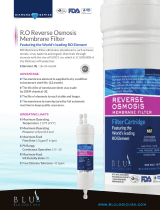
DOW FILMTEC™ MEMBRANES .......................................................................... 110
BURKERT DIVERSION VALVE ............................................................................. 114
7. WARRANTY INFORMATION ..................................................................... 120
OWNER’S LIMITED WARRANTY .......................................................................... 121
SE Models 2 4/24/2017

This Page Intentionally Left Blank
SE Models 3 4/24/2017

PART 1: INTRODUCTION
SE Models 4 4/24/2017

ACRONYMS AND DEFINITIONS
ACRONYM/SYMBOL
DEFINITION
FWF
FRESH WATER FLUSH
RO
REVERSE OSMOSIS
PSI
POUNDS PER SQUARE INCH
GPM
GALLONS PER MINUTE
GPD
GALLONS PER DAY
TDS
TOTAL DISSOLVED SOLIDS
PPM
PARTS PER MILLION
TCF
TEMPERATURE CORRECTION FACTOR
LP SWITCH
LOW PRESSURE SWITCH
HP SWITCH
HIGH PRESSURE SWITCH
Φ
PHASE
SE Models 5 4/24/2017

CONGRATULATIONS
Your Dometic SeaXchange SE-Series Reverse Osmosis System is a durable piece of
equipment that, with proper care, will last for many years. This User’s Manual outlines
installation, operation, maintenance, and troubleshooting details vital to the sustained
performance of your system.
SAFETY
The safety section of this User’s Manual outlines the various safety headings used
throughout this manual’s text and are enhanced and defined below:
NOTE: INDICATES STATEMENTS THAT PROVIDE FURTHER INFORMATION AND
CLARIFICATION.
NOTE: PRIOR TO OPERATING OR SERVICING YOUR REVERSE OSMOSIS
SYSTEM, THIS USER’S MANUAL MUST BE READ AND FULLY UNDERSTOOD.
KEEP THIS AND OTHER ASSOCIATED INFORMATION FOR FUTURE REFERENCE
AND FOR NEW OPERATORS OR QUALIFIED PERSONNEL NEAR THE SYSTEM.
CAUTION: INDICATES STATEMENTS THAT ARE USED TO IDENTIFY
CONDITIONS OR PRACTICES THAT COULD RESULT IN EQUIPMENT OR OTHER
PROPERTY DAMAGE.
DO NOT UNDER ANY CIRCUMSTANCE; REMOVE ANY CAUTION,
WARNING, OR OTHER DESCRIPTIVE LABELS FROM THE SYSTEM.
WARNING: INDICATES STATEMENTS THAT ARE USED TO IDENTIFY
CONDITIONS OR PRACTICES THAT COULD RESULT IN INJURY OR LOSS OF LIFE.
FAILURE TO FOLLOW WARNINGS COULD RESULT IN SERIOUS INJURY OR EVEN
DEATH.
SE Models 6 4/24/2017

PRINCIPLES OF REVERSE OSMOSIS
REVERSE OSMOSIS
How Fresh Water Is Produced
Reverse Osmosis or “RO” is a process where freshwater water is produced by
pumping saltwater through a semi-permeable membrane.
Osmosis
Osmosis is a naturally occurring process where a weak solution will cross a semi-
permeable membrane to mix with a highly concentrated solution. For example a
freshwater solution will naturally want to mix with a saltwater solution.
Reverse Osmosis
To reverse this process work is put into the system using a pump. The pump
causes pressure to build up on the saltwater side of the membrane. This pressure
forces water across the semi-permeable membrane. The membrane is designed
to allow the water molecules to pass while preventing the salt and other solids from
doing so. Fresh water is collected on the other side of the membrane as a result.
SE Models 7 4/24/2017

UNIT SPECIFICATIONS
SE MODEL
350
600-1
600-2
800
Configuration
1 Vessel
1 Vessel
2 Vessel
2 Vessel
Feed Water Source
Sea Water
Sea Water
Sea Water
Sea Water
Rated production gpd
(gpm)
350(0.24) 600(0.41) 600(0.41) 800(0.55)
Rejection and Flow Rates
Nominal Salt
Rejection %
99.4% 99.4% 99.4% 99.4%
Minimum Feed Flow
gpm (lpm)
2.5 (9.5) 2.5 (9.5) 2.5 (9.5) 2.5 (9.5)
Minimum Concentrate
Flow gpm (lpm)
2.26 (8.3) 2.1 (7.9) 2.1 (7.9) 1.94 (7.3)
Connections
Feed inch
¾” Hose
¾” Hose
¾” Hose
¾” Hose
Product inch
3/8” QC 9.5mm
3/8” QC 9.5mm
3/8” QC 9.5mm
3/8” QC 9.5mm
Concentrate inch
1/2” QC 12.7mm
1/2” QC 12.7mm
1/2” QC 12.7mm
1/2” QC 12.7mm
Membranes
Membrane Per Vessel
1
1
1
1
Membrane Quantity
1
1
2
2
Membrane Size
2521
2540
2521
2540
Pumps
High Pressure Pump
Type
Piston
Piston
Piston
Piston
HP motor amps
14.0/7.0
14.0/7.0
14.0/7.0
14.0/7.0
High Pressure Motor
HP (kw)
1.5
1.5
1.5
1.5
Booster motor amps
7.2/4.3
7.2/4.3
7.2/4.3
7.2/4.3
Booster Pump RPM
@ 60
1750 1750 1750 1750
Electrical
Voltage
115/230V 60Hz
1Φ
115/230V 60Hz
1Φ
115/230V 60Hz
1Φ
115/230V 60Hz
1Φ
Amp Draw
21.2/11.3
21.2/11.3
21.2/11.3
21.2/11.3
System Dimensions
L x W x H inch (cm)
25.75”x16.99”x
14.09”
(65.4x43.2x35.8)
25.75”x16.99”x
14.09”
(65.4x43.2x35.8)
44.85”x16.99”x
14.09”
(113.9x43.2x35.8)
44.85”x16.99”x
14.09”
(113.9x43.2x35.8)
Weight lb. (kg)
117.5 (53.3)
120.5 (54.65)
125 (56.7)
131 (59.4)
SE Models 8 4/24/2017

OPERATION SPECIFICATIONS
BEFORE STARTING
The reverse osmosis process causes the concentration of impurities. The impurities may
precipitate (fall out of solution) when their concentration reaches saturation levels when
operated beyond rated production. This precipitation can scale or foul the membranes.
In order to prevent this, your SE unit should never be operated over the rated production
listed in the UNIT SPECIFICATIONS chart (page 8) and also should not be run above
850psi pump pressure. Water temperature and inlet water ppm are variables that affect
flow rate and pump pressure
CAUTION: THE RATED PRODUCTION WILL HAVE TO BE CORRECTED FOR
TEMPERATURE OF THE SEA WATER WHEN DETERMINING RATED FLOW FOR
YOUR UNIT. SEE ‘TEMPERATURE CORRECTION FACTORS FOR WATER
PRODUCTION’ CHART (PAGE 12-13) FOR AN EXAMPLE ON CORRECTING THE
RATED FLOW RATE.
PRE-FILTRATION
SE-Series systems are supplied with a 25-micron (part number 252404292) and 5-micron
(part number 252404291) HIGH CAPACITY sediment filters. These filters are made from
Typar™ filter media and contain 30% more media than most 2.5” x 10” pleated sediment
cartridges To prevent damage to the system, we recommend using the sediment filters
supplied with this system. Change the pre-filters once the pressure gauge labeled
FILTER OUT is 15psi or lower.
BOOSTER PUMP
SE-series systems are supplied with a stainless steel centrifugal pump. The pump must
be located below the water line to maintain a positive suction head for priming purposes.
Refer to page 94 for the booster pump manual.
THE BOOSTER PUMP MUST NEVER BE RUN DRY. OPERATING THE PUMP
WITHOUT SUFFICIENT FEED WATER WILL DAMAGE THE PUMP.
SE Models 9 4/24/2017

OPERATION SPECIFICATIONS
HIGH PRESSURE PUMP
The pump used on the SE-Series systems is a piston type constructed of stainless steel.
Follow these guidelines to ensure proper operation of the pump:
• Refer to the WM series General Pump in manufacturer’s index for recommended
maintenance (page 88).
• The pump must NEVER be run dry. Operating the pump without sufficient feed
water will damage the pump.
• ALWAYS use the required filters when operating the unit. The high pressure pump
is susceptible to damage from sediment and debris.
• If any damage occurs to your system’s pump, a re-build kit is available. Contact
your local dealer or distributor and inform them of your system’s model and pump
size.
• Follow the instructions in the FWF section on page 42.
MEMBRANES
SE-Series reverse osmosis systems come pre-loaded with DOW FILMTEC™ sea water
membranes unless otherwise specified. For the best longevity of membranes, use the
manufacturer’s recommended prefilters, operate it within it limits, and ensure the system
is performing its regular FWF. Membrane element guidelines can be found in the Dow
FILMTEC™ on page 110.
DIVERSION VALVE
The diversion valve controls the product water after the membranes. If the controller
determines that the salinity of the water is acceptable, (based on the salinity set point) it
will energize the diversion valve solenoid, causing the water to flow to the vessels tank.
If the electrical portion of the solenoid fails or the controller fails to energize the solenoid,
a manual bypass on the diversion valve may be utilized if the product water is found to
be acceptable. Refer to picture on page 55 and the Diversion Valve Manual on page 114.
SYSTEM CONTROLLER
The controller is a logic based pc board that can analyze and control the electrical
components within the system. Its primary functions are to monitor safety switches (high
and low pressure), perform the program sequence of operations to optimize the start,
normal operation, and shutdown sequence. Refer to the Watermaker System Controller
Manual on page 76.
SE Models 10 4/24/2017

OPERATION SPECIFICATIONS
PRODUCT WATER
Dometic SeaXchange SE-Series Reverse Osmosis Systems are designed to produce
product water at the capacities indicated. For example, the SE 800 produces 800 gallons
per day or 0.55 gallons per minute (800gpd ÷ 24hrs/day ÷ 60mins/hr=0.55gpm) of product
water at the listed operating test conditions.
Rejection
The amount of total dissolved solids (TDS) rejected by the membrane is expressed
as a percentage. For example, a 99.4% rejection rate means that 99.4% of total
dissolved solids do not pass through the membrane. To calculate the % rejection,
use the following formula:
% Rejection = [(Feed TDS – Product TDS) / Feed TDS] x 100
Example:
99.4% = [(35,000-210)/35,000] x 100
Recovery
The amounts of product water recovered for use is expressed as a percentage. To
calculate % recovery, use the following formula:
% Recovery = (Product Water Flow Rate / Feed Water Flow Rate) x 100
Example:
36% = (1.52/4.22) x 100
NOTE: ALL TDS FIGURES MUST BE EXPRESSED IN THE SAME UNITS,
TYPICALLY PARTS PER MILLION (PPM) OR MILLIGRAMS PER LITER (MG/L).
SE Models 11 4/24/2017

OPERATION SPECIFICATIONS
TEMPERATURE CORRECTION FACTORS FOR WATER PRODUCTION
To find your SE-series unit’s rated flow at a given temperature, refer to the chart to find
the Temperature Correction Factor (TCF). Divide the rated product flow at 77°F by the
TCF. The result is the corrected product flow at current water inlet temperature. The
water temperature can be found on the main screen. See the example on the next
page.
SE Models 12 4/24/2017

OPERATION SPECIFICATIONS
TEMPERATURE CORRECTION FACTORS FOR MEMBRANE (FORMULA)
If a system is rated to produce 1.25 gpm of product water @ 77˚ F. The same system will
produce more water at a higher temperature. It will also produce less water at a lower
temperature. Use the temperature correction table to obtain the correct flow.
Corrected Flow Rate = (Measured Rated Flow) ÷ (TCF @ Feed Water Temp.)
Example:
1.25 gpm @ 59˚ F (1.25÷1.42=.88 gpm)
1.25 gpm @ 77˚ F (1.25÷1=1.25 gpm)
1.25 gpm @ 84˚ F (1.25÷0.89=1.4 gpm)
NOTE: Fahrenheit/Celsius conversion: F = (°C x 9/5) + 32
SE Models 13 4/24/2017

PART 2: INSTALLATION AND COMMISSIONING
SE Models 14 4/24/2017

INSTALLATION KIT
ITEMS INCLUDED WITH EACH SYSTEM
MAIN INSTALLATION ITEMS
□
252404258 – stainless steel booster pump and motor assembly
□ 252404295 - 2.5” x 10” carbon block filter
□ 252404172 - 2.5”x 10” double pre-filter assembly
□ 252404326 – 2.5” filter housing wrench
□ 252404202 – 20’ of ¾“ white double walled hose. (Not to be used on the suction side of feed pump.
Always use wire reinforced hose from the seacock to the suction side of the feed pump.)
□ 252404004 – 50’ of ¼ ” Spot Zero white nylon tubing (for FWF)
□ 252404003 – 50’ of ½” Spot Zero white nylon tubing (for overboard)
□ 252404002 - 50’ of 3/8” Spot Zero white nylon tubing (for product)
□ 252404099 – (2) 3/8” x ½” connectors
□ 252404114 – (2) 3/8” tee
□ 252404109 – (3) 3/8”QC x 3/8”QC 90° elbow
□ 252404118 – (18) 3/8” red locking clip
□ 254404094 – (3) ½” elbow tube
□ 252404093 –(1) ½” connector male
□ 252404115 – (2) ½” tee
□ 252404115 – (10) ½” red locking clip
□ (10) – Blue clamp aid safety covers
□ (8) – Stainless steel 5/16” x 1” lag bolts
□ (8) – Stainless steel 5/16” flat washers
CONSUMABLE ITEMS
□ 252404192 – 2.5” x 10” 25 micron pre-filter
□ 252404191 – 2.5” x 10”5 micron pre-filter
□ 252404015 – 21oz. bottle CAT pump oil
□ 252404179 – SW30 2540 membrane
□ 252404178 – SW30 2521 membrane
OPTIONAL ITEMS
□ 252404298 – high capacity prefilter (4.5” X 20”)
□ 252404317 – high capacity prefilter assembly
□ 252404225 – remote control and 50’ cable
□ 252404121 – spare fitting kit
□ 252404040 – hand held TDS meter
□ Membrane and vessel array upgrade
NOTE: Items listed are 1 unit supplied unless noted within parentheses.
SE Models 15 4/24/2017

DIMENSIONS
SE Models 16 4/24/2017

DIMENSIONS
SE Models 17 4/24/2017

DIMENSIONS
SE Models 18 4/24/2017

MOUNTING
The freestanding system should be bolted down and securely fastened. Refer to mounting
template below.
FEET/HOLE LOCATIONS
SE Models 19 4/24/2017

ELECTRICAL REQUIREMENTS
ELECTRICAL
The SE-Series systems are available in 1Φ (phase).
• 115 volts at 21.2 amps (including booster pump)
• 230 volts at 11.3 amps (including booster pump)
• 60 Hertz available in both the 115 volt and 230 volt units
NOTE: IT’S RECOMMENDED THAT A QUALIFIED ELECTRICIAN WIRE YOUR
SYSTEM IN ACCORDANCE WITH ALL APPLICABLE CODES, RULES, AND
REGULATIONS.
WARNING: TO REDUCE THE RISK OF ELECTRICAL SHOCK, THE
INCOMING POWER SUPPLY MUST INCLUDE A PROTECTIVE GROUND.
SE Models 20 4/24/2017
/