
Installation and Care Guide
Bath with Airjets
Retain serial number for reference:
Conserver le numéro de série pour référence:
Guarde el número de serie para referencia:_____________________
Français, page ″Français-1″
Español, página ″Español-1″
1198327-2-C

Installation Instructions
WARNING: When using electrical products, basic precautions should always be followed,
including the following:
WARNING: Risk of electric shock. Connect only to a circuit protected by a Ground-Fault
Circuit-Interrupter (GFCI)*.
Building materials and wiring should be routed away from the blower body and other heat-producing
components of the unit.
Install to permit access for servicing.
A pressure wire connector marked ″Earth/Ground″ is provided within the wiring compartment. To reduce
the risk of electric shock, connect this connector to the grounding terminal of your electric service or supply
panel with copper wire equivalent in size to the circuit conductor supplying this equipment.
Pressure wire connectors are provided on the exterior of the junction box or control within this unit to permit
connection of a bonding conductor between this unit and all other exposed metal in the vicinity, as needed to
comply with local requirements.
An equipment grounding terminal is provided in the field wiring compartment. To reduce the risk of electric
shock, this terminal must be connected to the grounding means provided in the electric supply panel with a
conductor equivalent in size to the circuit conductors supplying this equipment.
Grounding is required. The unit should be installed by a qualified service representative, and grounded.
WARNING: Risk of injury or property damage. Please read all instructions thoroughly before
beginning installation.
WARNING: Risk of electric shock. A qualified electrician should make all electrical connections.
WARNING: Risk of electric shock. Disconnect power before servicing.
NOTICE: Follow all local plumbing and electrical codes. In Canada, install this unit in accordance with
the Canadian Electrical Code, Part 1.
*Outside North America, this device may be known as a Residual Current Device (RCD).
Product Information
Electrical Requirements
The installation must have a Class A Ground-Fault Circuit-Interrupter (GFCI)*. The GFCI protects against
line-to-ground shock hazards. Use a 220 - 240 V, 15A, 50/60 Hz dedicated service for the bath.
*Outside North America, this device may be known as a Residual Current Device (RCD).
Product Notices
WARNING: Risk of personal injury or property damage. Unauthorized modification may cause
unsafe operation or affect performance of the bath. Do not relocate the blower motor, or make other
modifications to the bath system in the absence of kit or other published instructions, as this could
adversely affect the performance and safe operation of the product. Kohler Co. shall not be liable
under its warranty or otherwise for personal injury or damage caused by any such unauthorized
modification. Refer to the ″Prepare the Blower - Remote Site″ section for blower motor relocation
requirements, recommendations, and section coverage information.
NOTICE: Keep the area around the blower motor clean and free of sawdust, insulation, dirt, or other
small loose debris. Such material could plug the blower motor air intake and reduce the air flow through
the blower.
1198327-2-C 2 Kohler Co.

Product Information (cont.)
Features
Factory assembled components include a blower motor, air harness, control, butterfly valves, chromatherapy
lights (certain models), electrical harnesses, and an illuminated user keypad. Other than power wiring and
plumbing connections, no assembly is required.
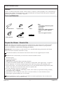
Tools and Materials
Prepare the Blower - Remote Site
NOTE: This bath can be installed as received or with the blower motor relocated to another location.
Refer to the appropriate sections throughout this manual for instructions related to your particular
installation. Read this section before relocating your blower.
IMPORTANT! Do not relocate or alter the PVC tee or coiled flexible tubing connected to the blower.
Follow the blower relocation instructions exactly.
All material needed for the relocation of the blower motor must be supplied by the installer.
Additional tools and materials you will need to relocate the blower motor:
•
Electrician pliers
•
Assorted screwdrivers
•
Adjustable wrench
•
Drill and bits to install the blower mounting fasteners
•
18 AWG non-metallic sheathed cable, two conductors with ground, with support clips, as required
•
One 4″ (102 mm) x 2″ (51 mm) electrical junction box with cover, gasket, and mounting screws
•
Three strain reliefs - one must fit the blower motor cover with standard National Pipe Thread (NPT)
threads. The other two must fit the holes in the new junction box.
•
Six wire connectors (wire nuts or equivalent)
•
1-1/2″ PVC or other rigid pipe with fittings, unions, PVC cement (or equivalent fastening method),
and support clips, as required
•
Four fasteners (such as flathead wood screws or concrete anchors) to secure the blower motor
•
Solid copper 8-gauge bonding wire, 36″ (914 mm)
Relocate the blower as close as possible to the bath to maximize performance. Do not relocate the
blower more than 15’ (4.5 m) from the bath.
Silicone Sealant
Pencil
Level
Safety Glasses
Tape Measure
Pipe Wrench
Plus:
• Conventional woodworking tools
and materials
• Drop Cloth
• Construction adhesive (optional)
• Cement* or mortar (optional)
• 2x4s
*
Do not use gypsum cement.
Kohler Co. 3 1198327-2-C

Prepare the Blower - Remote Site (cont.)
•
Position the blower 1-1/2″ (38 mm) above the floor. Do not mount the blower motor with the
blower motor discharge pointing up.
•
Use 1-1/2″ PVC or equivalent rigid piping.
•
The piping installation must meet the requirements of local plumbing or building codes. Ensure that
the installation does not reduce the fire rating of any walls. Piping must be supported at intervals
along the length in accordance with local codes.
•
Ensure that the blower motor location is clean and free of dust or debris.
•
Install an access panel for blower motor maintenance.
•
The 18 AWG minimum power cable to the blower motor must meet the requirements of all
applicable electrical or building codes. Ensure that the installation does not reduce the fire rating of
any walls.
•
The power cord must be supported at intervals along its length in accordance with local codes.
Power cords must not rest on surfaces or floors that are subject to flooding.
1198327-2-C 4 Kohler Co.

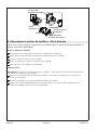
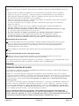
1. Prepare the Site
NOTICE: Measure your product for site preparation. Note the model number located on the blower, then
visit the product page at www.kohler.com for more information.
NOTICE: Provide adequate ventilation and a minimum 15 cubic feet (.4 cubic meters) air space in the
installed location for cooling the motor and to supply sufficient air for the blower. Do not install the
blower motor closer than 1″ (25 mm) from the wall or other objects.
NOTICE: Provide generous, unrestricted access to the blower. You must provide access for servicing the
blower and controls. The access must be located immediately next to the blower.
NOTICE: Do not lift the bath by the piping or blower, or use the piping or blower for structural support
of the bath. To avoid damage to the bath, lift at the sides of the bath.
NOTICE: Do not support the weight of the bath by the rim. Allow for a 1/16″ (2 mm) gap between the
finished material and the underside of the bath rim.
NOTICE: Ensure adequate clearance for faucets and valves.
NOTICE: Allow at least 2″ (51 mm) clearance between the edge of the bath rim and the finished wall.
NOTICE: For under-mount installation, go to www.kohler.com for information on the optional
under-mount kit for your bath model. Follow the installation instructions included with the under-mount
kit.
NOTE: Drop-in, alcove, under-mount, or corner installation is possible, depending on the product chosen.
Carefully unpack and inspect the new bath for damage before installation. If there is damage do not
install the bath; contact your dealer.
Make sure the flooring offers adequate support for your bath, and verify that the subfloor is flat and
level.
Construct 2x4 stud framing.
Install an access panel for future blower servicing. The access panel must be at least 34″ (864 mm)
wide by 15″ (381 mm) high.
Install the rough plumbing.
Install the drain to the bath according to the drain manufacturer’s instructions.
Protect the bath surface by positioning a clean drop cloth in the basin bottom.
Access
Panel
Construct according
to the product dimensions.
Construct 2x4
stud framing
according to the
product dimensions.
Position the
rough plumbing.
Verify that the subfloor
offers adequate support,
and is flat and level.
Alcove Drop-In
Position
the rough
plumbing.
Verify that the subfloor
offers adequate support,
and is flat and level.
Kohler Co. 5 1198327-2-C

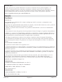
2. Install the Bath
NOTICE: Do not lift the bath by the piping or blower, or use the piping or blower for structural support
of the bath. To avoid damage to the bath, lift by the rim at the sides of the bath.
If the subfloor is not level, shim the bath support blocks or molded supports as necessary.
Option 1: Install Using Construction Adhesive
NOTE: Some models come with support blocks; some models have molded supports.
Apply a generous amount of high-quality construction adhesive to the bottom of the support blocks
or molded supports. With help, carefully lift the bath into position.
Option 2: Using a Cement or Mortar Bed
NOTE: Do not use gypsum cement or drywall compound for this application, as they will not provide an
acceptable, durable bond.
Set the bath in 1″ (25 mm) to 2″ (51 mm) of mortar cement.
Secure the Nailing-in Flanges (Alcove Units)
Drill a small pilot hole through the nailing-in flange at each stud. Add shims as needed.
Use large-head galvanized nails to secure the nailing-in flange to the studs.
Nail 1/4″ (6 mm) thick furring strips to the studs.
Install the Plumbing
Insert the drain tailpiece into the trap. Secure the drain tailpiece to the trap.
Stud
Cement or
Mortar Bed
Clear a space
for the blower.
Option 1
Furring
Strip
Nail
Option 2
Three Wall Alcove or Corner Installations
Support Blocks
Apply construction
adhesive.
Drill a small hole
through the nailing-in
flange at each stud.
1198327-2-C 6 Kohler Co.

Install the Bath (cont.)
Install the faucet valve.
Check the drain connections for leakage.
Kohler Co. 7 1198327-2-C

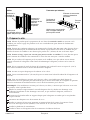
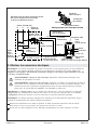
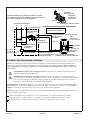
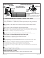
3. Make Electrical Connections
NOTE: The product model number is printed on a label on the blower side of the bath. This label also
identifies the electrical rating of the product. All baths come equipped with a wiring junction box and
are designed to operate between 220 V and 240 V at either 50 Hz or 60 Hz.
WARNING: Risk of electric shock. Disconnect the power before performing the following
procedures.
WARNING: Risk of electric shock. Connect the blower to a properly grounded Ground-Fault
Circuit-Interrupter (GFCI) or Residual Current Device (RCD). This will provide additional
protection against line-to-ground shock hazard. A 220-240 V, 15A, 50/60 Hz dedicated circuit is
required.
IMPORTANT! The load neutral is not used. There should be no connection to the load neutral terminal
on the Ground-Fault Circuit-Interrupter (GFCI) breaker. The green wire with the yellow stripe is the
equipment ground and needs to be connected to the neutral bus in the main circuit breaker box.
NOTE: The wiring harness includes an antenna for the optional remote control. Do not alter or damage
this antenna during installation.
Connect service to the junction box. The junction box contains blue, brown, and green with a yellow
stripe colored wires and a ground lug.
Follow local electrical codes. Bond in accordance with national and local codes.
Control Power
Junction Box
Blue (L1)
Wire Connector
Ground
(Green with
Yellow Stripes)
From Control
Brown (L2)
Wire Connectors
Electrician to provide
suitable strain relief.
* Connections to be Made
at the Circuit Breaker
Typical Wiring Connection for North America
Control
Blower Motor Cord
Control
Power Supply
External Power
Field Wiring
(From Junction Box
to GFCI Breaker)
* Equipment Ground
* Line Neutral
(White
Curly Wire)
Neutral Bus
(In Breaker Box)
240 V
120 V
120 V
*L2
240 V
*L1
Typical Two-Pole
Circuit Breaker
with GFCI
Breaker Box
L2
L1
N
120/240 VAC Source
Bond in accordance with national and
local codes. Open bonding lugs are
located at the top of the junction box.
No Connection
(Load Neutral)
1198327-2-C 8 Kohler Co.

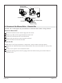
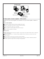
4. Disconnect the Blower Motor - Remote Site
NOTICE: This section applies only to installations in which the blower motor is being relocated.
Remove the Blower Motor
Disconnect the blower motor electrical plug from the control.
Remove any cable ties that support the blower motor cord.
Cut the PVC tube between the tee and the blower.
Remove and retain the four screws from the baseboard.
Remove the blower motor from the bath.
Prepare the Site
NOTE: Refer to the ″Prepare the Blower - Remote Site″ section for blower relocation details.
Prepare the site where the blower motor will be installed. The site must be within 15’ (4.5 m) of the
bath.
Install an access panel to service the blower motor.
Prepare the routing paths for the PVC piping and the new blower motor power cable. Follow all
applicable codes.
Baseboard
Control
To Blower Motor
Cover
Blower Motor
Mounting Screws
Blower Motor
Electrical Plug
Junction Box
Cut Pipe
Kohler Co. 9 1198327-2-C

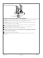
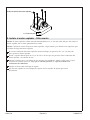
5. Mount the Blower Motor - Remote Site
NOTE: The blower motor must be mounted horizontally 1-1/2″ (38 mm) above the floor. Do not mount
the blower motor with the discharge pointing up.
NOTE: Refer to the ″Prepare the Blower - Remote Site″ section for other requirements for the blower
motor relocation.
At the new blower motor location, install a 1-1/2″ (38 mm) high block (not supplied) to support the
blower motor.
Install and support PVC or other 1-1/2″ rigid piping (not supplied) between the blower motor
location and the air harness.
Connect the new piping to the existing air harness without modifying the air harness. Align the new
pipe and secure the connection with PVC cement. Allow the PVC cement to cure according to the
manufacturer’s instructions.
Position the motor on the support block.
Fasten the blower motor to the new support block with the mounting screws previously retained.
Blower Motor Mounting Screws
1-1/2" (38 mm) Min
1198327-2-C 10 Kohler Co.

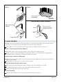
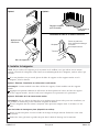
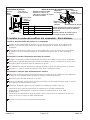
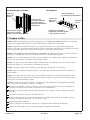
6. Terminate the Cable at the Blower - Remote Site
Route the Power Cable
Route 18 AWG or equivalent power cable (two conductors with ground) between the bath and
blower. Support and protect the cable. Follow local electrical codes.
Prepare the Blower for Remote Installation
Remove and retain the access cover screw from the back of the blower motor. As you are loosening
the screw, check periodically if the cover can be slid back on the electrical cable.
IMPORTANT! It is critical that the same wire combinations be maintained.
Mark the wires so they can be reconnected exactly the same.
When the cover is loose, use electrician pliers or equivalent to cut the electrical cable at the crimped
terminals.
Pull the free end of the electrical cord through the cover, insert, and strain relief nut.
Discard the existing strain relief nut and insert.
Reconnect the blower motor plug to the control.
Install a standard NPT threaded strain relief to the blower motor cover.
Connect the New Power Cable at the Blower Motor
USA: Mark the white conductors with red or black tape as required by the National Electric Code.
Route the new power cable leads through the blower motor access cover and strain relief.
Using wire nuts or other approved termination methods, terminate the conductors as follows:
•
Connect the black and white wires to the L1 conductor of the power cable.
•
Connect the tan and white wires to the L2 or N conductor of the power cable.
•
Connect the green with yellow stripe pigtail lead to the power cable ground conductor.
Reinstall the access cover on the blower motor using the screw previously removed.
Tighten the strain relief on the power cable at the blower motor.
Remove any dust or debris from the blower motor area.
Strain Relief
Remove screw, remove cover,
and cut existing cable about 4"
(102 mm) from the blower motor.
Plug
Blower Motor
Access Cover
Kohler Co. 11 1198327-2-C

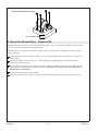
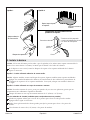
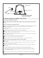
7. Install the Blower Cord at the Control - Remote Site
Install the Second Junction Box on the Control
Install a second junction box with external bonding lug, two strain reliefs, and a cover (not
supplied) on the blower adapter board on the control.
Connect a solid copper 8-gauge bonding wire from the bonding lug on the new junction box to the
spare bonding lug on the control. Follow all local electrical codes.
Reconnect the Blower Motor Power Cord
If required, reconnect the blower motor power cord at the control.
Route the blower motor power cord through a strain relief on the second junction box. Tighten the
strain relief.
At the end of the cut power cord, strip back the cable jacket about 3″ (76 mm).
Strip about 3/8″ (10 mm) of wire insulation from the remaining control wires.
Reconnect the Blower New Power Cable
Route the customer-supplied power cable from the blower through the other strain relief on the
second junction box. Tighten the strain relief.
Strip back the cable jacket about 3″ (76 mm).
For installations in the USA, mark the white wire with either red or black electrical tape as required
by the National Electric Code.
Use approved termination devices to terminate the conductors as follows:
•
Connect the black pigtail lead to the L1 conductor of the power cable.
•
Connect the blue pigtail lead to the L2 or N conductor of the power cable.
•
Connect the green with yellow stripe pigtail lead to the grounding or earthing conductor of the
power cable.
Install the cover on the new junction box.
8. Complete the Installation
Test Run the Bath
Fill the bath to a level at least 4″ (102 mm) above the top of the highest airjet.
Operate the bath for 5 minutes and check all piping connections for leaks. Check for leakage along
the front, sides, and back of the bath.
Wire Nut
Blue
Black
Strip back the jackets about
3" (76 mm) on the field cable
and on the blower motor pigtail.
From Control50 Hz
60 Hz
L1
L2
L1
N
GND GND
Green w/Yellow Stripe
Black
Blue
Ground (Green with
Yellow Stripe)
From Control
Cable to
Blower
Motor
New Field
Cable To
Blower Motor
Install junction box with cover
and bonding lug (not provided).
Route the cut end of the cord to
the new junction box. Add strain relief.
Blower Adapter
Board
Second
Junction Box
Blower
Motor Pigtail
Second Junction Box
Control Power Junction Box
1198327-2-C 12 Kohler Co.

Complete the Installation (cont.)
For additional information on bath operation, see the ″Operating Instructions″ section.
Finish the Installation
Install water-resistant wallboard and all finished wall, deck, and floor materials. Ensure a 1/16″ (2
mm) gap between the bath rim and the finished material.
Apply silicone sealant to seal all areas where the bath and finished wall or deck meet.
Install the faucet trim.
Clean-up After Installation
When cleaning up after installation, do not use abrasive cleansers, as they may scratch and dull the
bath surface. Use warm water and a liquid detergent to clean the surface of the bath.
Remove stubborn stains or paint with turpentine or paint thinner. Do not allow cleaners containing
petroleum distillates to remain in contact with any bath surface for long periods of time. Remove
plaster by carefully scraping with a wood edge. Do not use metal scrapers, wire brushes, or other
metal tools. Use a powder-type detergent on a damp cloth to provide mild abrasive action to any
residual plaster.
Important Safety Instructions
READ AND FOLLOW ALL INSTRUCTIONS
SAVE THESE INSTRUCTIONS
INSTRUCTIONS PERTAINING TO A RISK OF FIRE, ELECTRIC SHOCK, OR INJURY TO PERSONS
WARNING: When using electrical products, basic precautions should always be followed,
including the following:
DANGER: Risk of accidental injury or drowning. To reduce the risk of injury, do not permit
children to use this unit unless they are closely supervised at all times.
WARNING: Risk of personal injury. To avoid injury, exercise care when entering or exiting the
bath.
WARNING: Risk of electric shock. Do not permit electric appliances (such as a hair dryer, lamp,
telephone, radio, or television) within 5’ (1.5 m) of this bath.
WARNING: The use of alcohol, drugs, or medication can greatly increase the risk of fatal
hyperthermia. Prolonged immersion in hot water may induce hyperthermia. Hyperthermia occurs
when the internal temperature of the body reaches a level several degrees above the normal body
temperature of 98.6°F (37°C). The symptoms of hyperthermia include an increase in the internal
temperature of the body, dizziness, lethargy, drowsiness, and fainting. The effects of hyperthermia
include: (a) failure to perceive heat, (b) failure to recognize the need to exit the bath, (c)
unawareness of impending hazard, (d) fetal damage in pregnant women, (e) physical inability to
exit the bath, and (f) unconsciousness resulting in the danger of drowning.
WARNING: Risk of fetal injury. Pregnant or possibly pregnant women should consult a physician
before using the bath.
WARNING: Risk of hyperthermia or drowning. Do not use the bath immediately following
strenuous exercise.
Kohler Co. 13 1198327-2-C

Important Safety Instructions (cont.)
WARNING: Risk of hyperthermia or drowning. Water temperature in excess of 100°F (38°C) may
cause injury. Test and adjust the water temperature before use.
WARNING: Risk of personal injury. Never drop or insert any object into any opening.
Use this bath only for its intended purpose as described in this guide. Do not use attachments not
recommended by Kohler Co.
The bath must be connected only to a supply circuit that is protected by a Ground-Fault Circuit-Interrupter
(GFCI)*. Such a GFCI should be provided by the installer and should be tested on a routine basis. To test the
GFCI, press the test button. The GFCI should interrupt power. Press the reset button. Power should be
restored. If the GFCI fails to operate in this manner, the GFCI is defective. If the GFCI interrupts power to
the bath without the test button being pressed, a ground current is flowing, indicating the possibility of an
electric shock. Do not use this bath. Disconnect the bath and have the problem corrected by a qualified
service representative before using.
* Outside North America, this device may be known as a Residual Current Device (RCD).
1198327-2-C 14 Kohler Co.

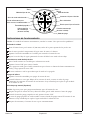
Operating Instructions
NOTE: If the unit does not function properly, please refer to the “Troubleshooting” section.
Start the Unit
Fill the bath at least 4″ (102 mm) above the top of the airjets.
Use your hand to test the water temperature before entering the bath.
Press the power icon on the user keypad to start the air system.
Adjust the air flow rate by pressing the up or down icon.
Select an Air Flow Mode
Rotate the outer ring on the keypad to select a mode.
Press the ″OK″ icon to activate the mode.
To turn a mode off, rotate the outer ring until the icon flashes green, then press the ″OK″ icon.
The icon will turn blue, indicating the mode is off.
Stop the Bath
Press the power icon to turn the air system off.
When the bath drains below the level sensors, an automatic 2 minute purge cycle occurs. The air
system operates at low speed to blow residual water out of the air harness.
Manual Purge Cycle (Optional)
NOTE: Follow these steps to manually purge residual water from the air system.
After stopping the air system and draining the bath, rotate the outer ring to the purge icon.
When the purge icon flashes blue, press the ″OK″ icon.
The purge icon flashes green as the manual purge begins. The air system operates at low speed to
blow residual water out of the air harness.
After 2 minutes, the air system stops automatically.
Care and Cleaning
For best results, keep the following in mind when caring for your KOHLER bath with airjets:
•
Always test your cleaning solution on an inconspicuous area before applying to the entire surface.
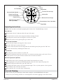
Air Flow Mode
Activates Mode Selected
Power On/Off
Indicator Bar
Decrease Flow or Surge
Increase Flow or Surge
Zone 1
Zone 2
Zone 3
Surge Mode
Purge Mode
Chromatherapy Cycle (if provided)
Chromatherapy Specific
Color (if provided)
Rotate Outer Ring to
Access Desired Mode
Kohler Co. 15 1198327-2-C

Care and Cleaning (cont.)
•
Wipe surfaces clean and rinse completely with water immediately after applying cleaner. Rinse and
dry any overspray that lands on nearby surfaces.
•
Do not allow cleaners to soak on surfaces.
•
Use a soft, dampened sponge or cloth. Never use an abrasive material such as a brush or scouring
pad to clean surfaces.
•
The ideal cleaning technique is to rinse thoroughly and blot dry any water from the surface after
each use.
•
Use a soft nylon brush on slip-resistant surfaces. Be sure to use a water-soluble cleaner (dissolves
100% in water).
•
Do not use powdered cleaners unless the cleaner is fully dissolved in water. Solid substances can
block the airjets.
•
Do not use full strength bleach or ammonia cleaning solutions. Chemically active cleaning
solutions can damage the surface.
•
Do not use abrasive cleansers or solvents on airjet surfaces. Abrasive cleaners and solvents can
damage the airjet surface.
Maintaining the Airjets
If cleaning the airjets is necessary due to hard water deposits, wet a soft, non-abrasive cloth with
white vinegar and wipe the plugged airjet holes. Immediately rinse the area with clean water to
avoid long-term exposure of the vinegar to the airjet surface.
Fill the bath with water to the top row of airjets. Drain the bath and press the purge button.
Cleaning Your User Keypad and Remote Control
Use a soft cloth to wipe the keypad and remote control after each use. If the surface becomes dirty,
use a non-abrasive soap and warm water to clean.
For detailed cleaning information and products to consider, visit www.kohler.com/clean. To order Care &
Cleaning information, call 1-800-456-4537.
Warranty
ONE-YEAR LIMITED WARRANTY
KOHLER plumbing products are warranted to be free of defects in material and workmanship for one year
from date of installation.
Kohler Co. will, at its election, repair, replace or make appropriate adjustment where Kohler Co. inspection
discloses any such defects occurring in normal usage within one (1) year after installation. Kohler Co. is not
responsible for removal or installation costs. Use of in-tank toilet cleaners will void the warranty.
To obtain warranty service contact Kohler Co. either through your Dealer, Plumbing Contractor, Home
Center or E-tailer, or by writing Kohler Co., Attn.: Customer Care Center, 444 Highland Drive, Kohler, WI
53044, USA, or by calling 1-800-4-KOHLER (1-800-456-4537) from within the USA and Canada, and
001-800-456-4537 from within Mexico, or visit www.kohler.com within the USA, www.ca.kohler.com from
within Canada, or www.mx.kohler.com in Mexico.
IMPLIED WARRANTIES INCLUDING THAT OF MERCHANTABILITY AND FITNESS FOR A
PARTICULAR PURPOSE ARE EXPRESSLY LIMITED IN DURATION TO THE DURATION OF THIS
WARRANTY. KOHLER CO. AND/OR SELLER DISCLAIM ANY LIABILITY FOR SPECIAL,
INCIDENTAL OR CONSEQUENTIAL DAMAGES. Some states/provinces do not allow limitations on how
long an implied warranty lasts, or the exclusion or limitation of special, incidental or consequential damages,
so these limitations and exclusions may not apply to you. This warranty gives you specific legal rights. You
may also have other rights which vary from state/province to state/province.
This is Kohler Co.’s exclusive written warranty.
1198327-2-C 16 Kohler Co.

Warranty
For Mexico
KOHLER CO.
It is recommended that at the time of purchase, you verify that all accessories and components are complete
in this package.
This Kohler product is warranted to be free of defects in material and workmanship for one (1) year from the
date of purchase as shown on the invoice or receipt.
1. Kohler Co. will only service its commercialized products through its authorized distributors.
2. To obtain warranty service, please present the invoice and corresponding warranty.
3. Through its authorized distributors, Kohler Co. promises to repair the defective product or provide a new
replacement or an equivalent model (in those cases that the model has been discontinued) when the product
is beyond repair, without any charge to the consumer.
4. The time of repair will not exceed six (6) weeks commencing on the date the product is received.
5. It is recommended that the consumer save the invoice or receipt as additional protection, as it may
substitute the warranty in the case that there is a discrepancy in the validity of the warranty.
EXCEPTIONS AND RESTRICTIONS
The Warranty will not be valid in the following cases:
1. When the product is not operated in accordance with the instructions concerning use and operation set
forth in the owner’s manual or installation instructions, and when the recommendations and warnings
included are not observed.
2. When the product has been modified or dismantled partially or totally; or has been used in a negligent
fashion and as a consequence has suffered damages attributable to the consumer, individual, or hardware not
authorized by Kohler Co.
3. This warranty does not cover the damages as a result of disaster such as fire or acts of God, including
flooding, earthquake, or electric storms, etc. To obtain a list of distributors in your area where you can
exercise your rights under this warranty, please call 001-800-456-4537.
KOHLER CO., KOHLER, WI 53044 U.S.A.
IMPORTER:
COMERCIALIZADORA INTERCERAMIC, S.A. DE C.V.
AV. CARLOS PACHECO NO. 7200, COL. MADERA 65
CHIHUAHUA, CHIH., MEXICO C.P. 31060
TEL: 52 (614) 429-11-11
IMPORTER:
GAMA MATERIALES Y ACEROS, SA DE CV
AVE LOS ANGELES NO. 1800
COL VALLE DEL NOGALAR, SAN NICOLAS DE LOS GARZA
N.L. MEXICO
R.F.C. GMA901220U11
TEL: 81-1160-5500
Kohler Co. 17 1198327-2-C

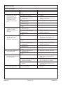
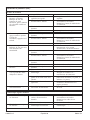
Troubleshooting
NOTICE: This section is for general aid only. A Kohler Co. Authorized Service Representative or qualified
electrician should correct any electrical problems. For warranty service, call 1-800-4KOHLER from within
the USA and Canada, or 001-800-456-4537 from within Mexico.
NOTE: The product model number is printed on a label on the blower side of the bath.
NOTE: For service parts information, visit your product page at www.kohler.com/serviceparts.
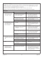
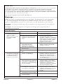
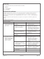
Bath System
Symptoms Probable Causes Recommended Action
1. User keypad does not
illuminate when Power
icon is pressed or the
outer ring is rotated.
A. No power to control. A. Check wiring and connect power.
B. Ground-Fault Circuit-Interrupter
(GFCI) or Residual Current
Device (RCD) tripped.
B. Reset GFCI or RCD. If it trips
again, refer to ″Ground-Fault
Circuit-Interrupter (GFCI) or
Residual Current Device (RCD)
trips when bath is turned on.″
C. Wiring harness from user
keypad to control is loose,
disconnected or damaged.
C. Check wiring for proper
connections. Replace the wiring
harness if necessary.
D. User keypad does not work. D. Replace the user keypad.
E. Control does not work. E. Replace the control.
2. Ground-Fault
Circuit-Interrupter (GFCI)
or Residual Current
Device (RCD) trips when
bath is turned on.
A. Electrical harness is wet or
damaged.
A. Check for wet connections. Dry the
connections and repair the leak.
Check for insulation or connector
damage. Replace the harness if
damaged.
B. Electrical wiring to the bath
junction box is wet or damaged;
or the power amperage is
inadequate.
B. Have a qualified electrician
diagnose and correct the problem
in accordance with applicable
building and electrical codes; or
increase the power amperage to 20
A.
C. Electrical wiring to the bath
power cord is wet or damaged.
C. Have a qualified electrician
diagnose and correct the problem
in accordance with applicable
building and electrical codes.
D. Blower motor is shorted
internally.
D. Replace the blower motor.
E. Control is shorted internally. E. Replace the control.
3. User keypad is
illuminated, but does not
respond to icons or outer
ring.
A. Control program is locked. A. Reset GFCI or RCD.
B. P5 plug assembly harness from
user keypad to control is loose,
disconnected, or damaged.
B. Check wiring for proper
connections. Replace the wiring
harness if necessary.
C. User keypad does not work. C. Replace the user keypad.
D. Control does not work. D. Replace the control.
4. Blower motor will not
start.
A. Power cord from blower motor
to control is loose, disconnected,
or damaged.
A. Check wiring for proper
connections.
B. Blower motor does not work. B. Replace the blower motor.
C. Control does not work. C. Replace the control.
5. Blower motor stops
r
unning and will not
immediately restart.
Keypad is illuminated.
A. Blower motor overheated and
protection device activated.
A. Check for blockage at air inlet.
Remove blockage and allow motor
to cool. Refer to ″User keypad is
illuminated, but does not respond
to icons or outer ring.″ and ″Blower
motor will not start.″
1198327-2-C 18 Kohler Co.

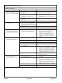
Troubleshooting (cont.)
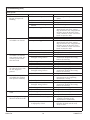
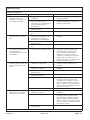
Bath System
Symptoms Probable Causes Recommended Action
6. Blower motor starts, some
but not all airjets are
bubbling.
A. Blower motor speed is too low. A. Increase speed set point to blower
motor.
B. Blower air inlet is blocked. B. Clear blower air inlet.
C. Blower motor does not work. C. Replace the blower motor.
D. Blower motor discharge is
blocked.
D. Clear blockage.
E. Airjets are clogged. E. Use a small between-the-teeth
dental brush and white vinegar.
Dip the brush in the vinegar, brush
the hole, rinse the brush in clean
water, and then use the wet rinsed
brush to rinse the hole.
F. Some zones are closed. F. Operate all zones.
7. Blower motor runs but no
air bubbles are formed.
A. Blower air inlet is blocked. A. Clean blower air inlet.
B. Airjets are clogged. B. Use a small between-the-teeth
dental brush and white vinegar.
Dip the brush in the vinegar, brush
the hole, rinse the brush in clean
water, and then use the wet rinsed
brush to rinse the hole.
C. Blower motor does not work. C. Replace the blower motor.
D. Control does not work. D. Replace the control.
8. Blower motor operates,
air bubbles are formed,
zone controls work, but
variable speed feature
does not work.
A. Blower air inlet is blocked. A. Clear blower air inlet.
B. Loose, disconnected, or
damaged wiring harness.
B. Check wiring for proper
connections. Replace the wiring
harness if necessary.
C. User keypad does not work. C. Replace the user keypad.
D. Blower motor does not work. D. Replace the blower motor.
E. Control does not work. E. Replace the control.
9. Blower motor won’t turn
off when the Power icon
on user keypad is
pressed.
A. User keypad does not work. A. Replace the user keypad.
B. Loose, disconnected, or
damaged wiring harness.
B. Check wiring for proper
connections. Replace the wiring
harness if necessary.
C. Control does not work. C. Replace the control.
10. A zone does not produce
air bubbles but another
zone operates normally.
A. Zone is not selected. A. Select the zone according to the
instructions in the ″Operating
Instr
uctions″ section.
B. Butterfly valve does not work. B. Replace the butterfly valve.
C. Loose, disconnected, or
damaged wiring harness.
C. Check wiring for proper
connections. Replace the wiring
harness if necessary.
D. User keypad does not work. D. Replace the user keypad.
E. Control does not work. E. Replace the control.
11. Surge mode does not
work.
A. User keypad does not work. A. Replace the user keypad.
B. Control does not work. B. Replace the control.
12. Water spillage or damage
observed under the bath.
A. Drain or overflow leaking. A. Repair or replace the drain
assembly according to the
manufacturer’s instructions.
B. Wall, deck, and/or shower door
is improperly sealed.
B. Apply silicone sealant at the seams
between the bath and the wall,
deck, or door.
Kohler Co. 19 1198327-2-C

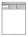
Troubleshooting (cont.)
Bath System
Symptoms Probable Causes Recommended Action
C. Cracked piping or air channels. C. Contact Kohler Co. using the
information on the back page.
13. Bath does not purge
automatically.
A. Level sensor wires are
disconnected.
A. Connect the level sensor wires.
Chromatherapy (some models)
Symptoms Probable Causes Recommended Action
14. Chromatherapy lights do
not work.
A. Loose, disconnected or damaged
wiring/connections.
A. Check wiring for proper
connections. Replace wiring if
necessary.
B. Control does not work. B. Replace control.
15. Chromatherapy does not
cycle.
A. Chromatherapy harness
assembly does not work.
A. Replace the chromatherapy harness
assembly.
1198327-2-C 20 Kohler Co.
Page is loading ...
Page is loading ...
Page is loading ...
Page is loading ...
Page is loading ...
Page is loading ...
Page is loading ...
Page is loading ...
Page is loading ...
Page is loading ...
Page is loading ...
Page is loading ...
Page is loading ...
Page is loading ...
Page is loading ...
Page is loading ...
Page is loading ...
Page is loading ...
Page is loading ...
Page is loading ...
Page is loading ...
Page is loading ...
Page is loading ...
Page is loading ...
Page is loading ...
Page is loading ...
Page is loading ...
Page is loading ...
Page is loading ...
Page is loading ...
Page is loading ...
Page is loading ...
Page is loading ...
Page is loading ...
Page is loading ...
Page is loading ...
Page is loading ...
Page is loading ...
Page is loading ...
Page is loading ...
Page is loading ...
Page is loading ...
Page is loading ...
Page is loading ...
-
 1
1
-
 2
2
-
 3
3
-
 4
4
-
 5
5
-
 6
6
-
 7
7
-
 8
8
-
 9
9
-
 10
10
-
 11
11
-
 12
12
-
 13
13
-
 14
14
-
 15
15
-
 16
16
-
 17
17
-
 18
18
-
 19
19
-
 20
20
-
 21
21
-
 22
22
-
 23
23
-
 24
24
-
 25
25
-
 26
26
-
 27
27
-
 28
28
-
 29
29
-
 30
30
-
 31
31
-
 32
32
-
 33
33
-
 34
34
-
 35
35
-
 36
36
-
 37
37
-
 38
38
-
 39
39
-
 40
40
-
 41
41
-
 42
42
-
 43
43
-
 44
44
-
 45
45
-
 46
46
-
 47
47
-
 48
48
-
 49
49
-
 50
50
-
 51
51
-
 52
52
-
 53
53
-
 54
54
-
 55
55
-
 56
56
-
 57
57
-
 58
58
-
 59
59
-
 60
60
-
 61
61
-
 62
62
-
 63
63
-
 64
64


Kohler K-1110-G-95 Installation guide
- Type
- Installation guide
- This manual is also suitable for
Ask a question and I''ll find the answer in the document
Finding information in a document is now easier with AI
in other languages
- français: Kohler K-1110-G-95 Guide d'installation
- español: Kohler K-1110-G-95 Guía de instalación
Related papers
-
Kohler K-9166-95 Installation guide
-
Kohler 1124-GLA-0 Installation guide
-
-
-
Kohler K-1357-GRA-0 Installation guide
-
Kohler 1446-NA Installation guide
-
-
-
Kohler K-1948-LAW-0 Installation guide
-
Kohler 5702-GW-0 Installation guide
Other documents
-
Scosche backSTAGE p2 User manual
-
Empava EMPV-JT011 User guide
-
Sterling 77301100-0 Installation guide
-
Eaton CHFN115GF Installation guide
-
Sterling Plumbing Sunfield™ Installation guide
-
-
-
-
Jacuzzi SALON Installation And Operating Instructions Manual
-
Hubbell Wiring Device-Kellems PD3026 Installation guide