
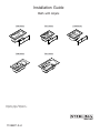
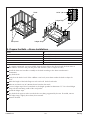
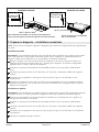
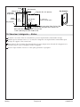
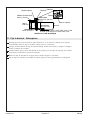
Installation Guide
Bath with Airjets
Français, page “Français-1”
Español, página “Español-1”
7726 Series 7727 Series 7728 Series
7730 Series 7731 Series
1139487-2-H

INSTALLATION INSTRUCTIONS
WARNING: When using electrical products, always follow basic precautions, including the
following:
DANGER: Risk of electric shock. To reduce the risk of electrical shock, connect the pump or
blower only to a properly installed Ground-Fault Circuit-Interrupter (GFCI). Do not remove the
plug grounding pin. Do not use a grounding adapter.
WARNING: Risk of injury or property damage. Please read all instructions thoroughly before
beginning the installation, including the following requirements.
WARNING: Risk of electric shock. A qualified electrician should make all electrical connections.
WARNING: Risk of electric shock. Disconnect power before servicing.
Building materials and wiring should be routed away from the pump or blower body and other
heat-producing components of the unit.
Grounding is required. The unit should be installed by a qualified service representative and grounded.
Install to permit access for servicing.
An equipment grounding terminal is provided in the field wiring compartment. To reduce the risk of electric
shock, this terminal must be connected to the grounding means provided in the electric supply panel with a
conductor equivalent in size to the circuit conductors supplying this equipment.
Install this unit in accordance with the Canadian Electrical Code, Part I.
NOTE: Follow all local plumbing, building, and electrical codes.
Product Information
Electrical Requirements
NOTE: If the supply cord is damaged, it must be replaced by the manufacturer, its service agent, or
similarly qualified persons in order to avoid a hazard.
The installation must include a Class A Ground-Fault Circuit-Interrupter (GFCI). The GFCI protects
against line-to-ground shock hazard. Use a 120 V, 15 A, 60 Hz dedicated service for the bath with
airjets.
Product Notices
WARNING: Unauthorized modification of the pump or blower may cause unsafe operation and
poor performance of the product. Do not relocate the pump or blower, or make other modifications
to the system, as this could adversely affect the performance and safe operation of the product.
Sterling shall not be liable under its warranty or otherwise for personal injury or damage caused by
any such unauthorized modification.
Factory-Assembled Features
Factory installed components include: blower with power supply cord, air switch transmitter, and
airjets.
Connections and Service Access
Before installation, verify proper access to the final connections.
1139487-2-H 2 Sterling

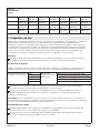
Table of Contents
INSTALLATION INSTRUCTIONS ..................................................... 2
Tools and Materials ............................................................... 3
Before You Begin ................................................................. 3
Roughing-In ..................................................................... 5
Prepare the Site ................................................................. 6
Rough-In the Plumbing – Alcove Installations ............................................ 7
Rough-In the Plumbing – Drop-In Installations ............................................ 8
Install a Mortar Cement Bed (recommended) ............................................ 9
Prepare the Bath – Alcove Installations ................................................ 10
Install the Optional Apron – Alcove Installations .......................................... 11
Prepare the Bath – Drop-In Installations ............................................... 12
Install the Electrical Outlet ......................................................... 13
Position the Bath ................................................................ 14
Secure the Bath – Alcove .......................................................... 15
Secure the Bath – Drop-In ......................................................... 16
Make Electrical Connections - Dedicated Circuit Models ................................... 17
Install the Drain ................................................................. 17
Complete the Finished Wall ........................................................ 18
Confirm Proper Operation .......................................................... 19
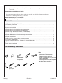
Tools and Materials
Before You Begin
CAUTION: Risk of personal injury. Do not select a large rim-mount faucet or large deck-mount
faucet for this product. These faucets may be inadvertently used as a means of support and are not
appropriate or safe for this installation. Select a wall-mount faucet or alternative deck-mount faucet.
CAUTION: Risk of property damage. Use clear 100% silicone sealant to the required areas when
instructed. Do not use latex-based sealant or other caulks. Do not add silicone sealant to any other
areas. The inappropriate type and application of sealant may trap moisture and could result in
mold, leakage, or mildew over the life of the product.
NOTICE: Risk of product damage. Do not lift the bath by the piping or blower. Do not use the piping or
blower for structural support of the bath. Lift the bath by the rim at multiple points.
NOTICE: Risk of product damage. Do not install the bath over open floor joists. The basin area requires
no additional support when the subfloor is level and square with the stud framing. Install the bath on an
adequately supported, level subfloor. Shimming is required if the subfloor is not level.
Plus:
Tin Snips
Clear 100%
Silicone Sealant
• Conventional woodworking
tools and materials
• Drop cloth
• Mortar cement (recommended)
• 1x4s, and 2x4s or 2x6s
• Hole saw
• Galvanized or plated non-tapered
flathead screws
• Furring Strips
Sterling 3 1139487-2-H

Before You Begin (cont.)
NOTICE: Risk of product damage. Select non-tapered flathead screws that are galvanized or plated,
consulting with local building codes for the required type of coating. The coating on the screws will
eliminate the occurrence of rust marks on your product.
Observe all applicable plumbing, electrical, and building codes.
This drop-in bath is designed for recessed, island, or alcove installations with an apron.
Accessories that require backing or support are not recommended for this installation.
Do not remove the old bath before you unpack and inspect the new unit.
For remodeling installations: (1) Measure the existing framework before removing the existing bath
to make sure that the new bath will fit in the existing framework. (2) Make sure that the drain
outlet and drain line is in the correct location. (3) Do not remove the existing bath until the new
bath is unpacked inspected for shortages or damage. Report any shortages or damage immediately.
Confirm adequate mounting and connection space for the water supply and drain installation.
Keep the liner (provided) in place until construction is complete.
If you encounter any installation or performance problems, please do not hesitate to contact Sterling
at 1-888-STERLING in the USA or 001-877-680-1310 in Mexico.
Sterling reserves the right to make revisions in the design of products without notice, as specified in
the Price Book.
1139487-2-H 4 Sterling

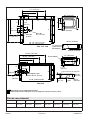
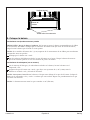
Roughing-In
ABCDE FG
7726 32″
(813 mm)
32-1/4″
(819 mm)
16″
(406 mm)
10″
(254 mm)
22″
(559 mm)
31-1/4″
(794 mm)
30-1/4″
(768 mm)
Ledger Strip Locations
Recommended Support Clip Location (5 Total)
17"
(432 mm)
Overflow Centerline
A
20-5/16"
(516 mm)
3/16"
(5 mm)
C
Without
Apron
72" (1829 mm)
11-3/4"
(298 mm)
7630, 7631
D
E
8"
(203 mm)
4"
(102 mm)
72-1/8" (1832 mm) Min
72-1/4" (1835 mm) Max
Drain Cutout
14-3/4" (375 mm)
57-3/8" (1457 mm)
28-3/4" (730 mm)
43-3/8" (1102 mm)
11-3/4"
(298 mm)
Ø 2" (51 mm) Drain
F
C
G
18-3/4"
(476 mm)
8-3/4"
(222 mm)
C
G
F
E
8"
(203 mm)
4" (102 mm)
Ø 2" (51 mm)
Drain
60-1/8" (1527 mm) Min
60-1/4" (153 mm) Max
Drain Cutout
17" (432 mm)
Overflow Centerline
16" (406 mm)
44" (1118 mm)
30" (762 mm)
60" (1524 mm)
A
8-3/4" (222 mm)
18-3/4" (476 mm)
20-5/16" (516 mm)
C
B
D
B
7726, 7727, 7728
Sterling 5 1139487-2-H

Roughing-In
(cont.)
7727 36″
(914 mm)
36-1/4″
(921 mm)
18″
(457 mm)
12″
(305 mm)
24″
(610 mm)
35-1/4″
(895 mm)
34-1/4″
(870 mm)
7728 42″
(1067 mm)
42-1/4″
(1073 mm)
21″
(533 mm)
15″
(381 mm)
27″
(686 mm)
41-1/4″
(1048 mm)
40-1/4″
(1022 mm)
7730 36″
(914 mm)
N/A 18″
(457 mm)
12″
(305 mm)
24″
(610 mm)
35-1/4″
(895 mm)
34-1/4″
(870 mm)
7731 42″
(1067 mm)
N/A 21″
(533 mm)
15″
(381 mm)
27″
(686 mm)
41-1/4″
(1048 mm)
40-1/4″
(1022 mm)
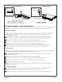
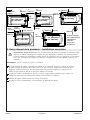
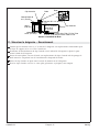
1. Prepare the Site
NOTICE: All dimensions shown in the ″Roughing-In″ section are nominal. The stud opening tolerance is
+1/8″ (3 mm)/-0. Carefully measure your fixture before determining enclosure size. Some shimming
between the stud frame and the fixture may be required. If a firewall is required, rough-in dimensions will
have to increase according to the thickness of the firewall material. Stud opening dimensions must be
measured toward the exposed side of the wall material. Dimensions given in the rough-in information are
crucial for proper installation. Construct the framing and plumbing accurately.
Plumbing
Install the drain line according to the drain manufacturer’s instructions. Locate the drain line and
trap using the dimensions given in the ″Roughing-In″ section.
Subfloor Construction
NOTICE: The bath must be level and resting on its feet. Therefore, constructing a subfloor that is level
and can support the load weight of the bath is crucial.
Floor support under bath
model:
7726 Must provide for a
minimum load of:
40 lbs/square foot (197 kg/square meter).
7727 40 lbs/square foot (193 kg/square meter).
7728 39 lbs/square foot (188 kg/square meter).
7730 41 lbs/square foot (200 kg/square meter).
7731 41 lbs/square foot (200 kg/square meter).
Construct a level subfloor made of plywood. If a material other than plywood is used, friction may
cause squeaking over time.
Verify the subfloor is level. If the subfloor is not level, install a mortar cement bed (recommended)
to level the subfloor. Refer to the ″Install a Mortar Cement Bed (recommended)″ section.
NOTE: If the subfloor is not level and a mortar cement bed will not be installed, you will be instructed in
the ″Prepare the Bath″ section to place a felt pad on the subfloor and add shims underneath the bath to
achieve level.
Framing Considerations
Plan the location of the bath to allow clearance for (1) drainage through the floor joists or slab and
(2) convenient plumbing installation.
Provide access to all plumbing connections to simplify future maintenance. Include access at the
back of the plumbing wall whenever possible.
If a shower door will be installed, refer to the shower door manufacturer’s instructions for any
special framing considerations such as double studding at the front corners of the framing.
1139487-2-H 6 Sterling

2. Rough-In the Plumbing – Alcove Installations
C
7726 16″ (406 mm)
7727 18″ (457 mm)
7728 21″ (533 mm)
7730 18″ (457 mm)
7731 21″ (533 mm)
NOTE: If plumbing will be installed on the unfinished stud wall, install the supplies after the bath is
installed.
Position the plumbing according to the roughing-in information. Cap the supplies and check for
leaks.
For above-the-floor drain installations: Cut the hole in the floor for the drain line. For
through-the-floor drain installations: Cut the hole in the floor for the drain assembly. The drain
connection should be made directly under the overflow drain. Leave room to connect the piping.
Install the water supplies according to the faucet manufacturer’s instructions. Cap the supplies and
check for leaks.
Strap the water supply connections to the stud framing.
Install the shower valving according to the manufacturer’s instructions. Do not install the trim at
this time.
Optional
Optional
Blocking
Blocking
Supply Valves
Water Supply
Shower Elbow
24"
(610 mm)
Min
8-3/4" (222 mm) for series 7726, 7727 and 7728
11-3/4" (298 mm) for series 7730 and 7731
C
Sterling 7 1139487-2-H

3. Rough-In the Plumbing – Drop-In Installations
CAUTION: Risk of personal injury. Do not select a large rim-mount faucet or large deck-mount
faucet for this product. These faucets may be inadvertently used as a means of support and are not
appropriate or safe for this installation. Select a wall-mount faucet or alternative deck-mount faucet.
NOTE: Do not install the trim at this time.
Before installing a rim- or deck-mount faucet, measure and cut a piece of 3/4″ exterior grade
plywood to act as a support under the bath rim. Cut a piece of plywood large enough to support
the faucet components and extend beyond the area where the faucet will be installed.
Install the water supply pipes at one of the specified faucet locations. Refer to the faucet
manufacturer’s instructions for proper installation.
Strap the supply lines to the stud framing.
Install the valves according to the faucet manufacturer’s instructions.
60" (1524 mm) x
32" (813 mm)
4" (102 mm)
3-1/8"
(79 mm)
3-1/8" (79 mm)
6-1/2"
(165 mm)
17-1/4"
(438 mm)
13"
(330 mm)
12"
(305 mm)
12"
(305 mm)
60" (1524 mm)
x 42" (1067 mm)
60" (1524 mm) x
36" (914 mm)
Install the faucet
to the rim and
plywood according
to the faucet
manufacturer's
instructions.
Faucet Location
Rim
72" (1829 mm) x
42" (1067 mm)
3"
(76 mm)
16"
(406 mm)
27" (686 mm)
72" (1829 mm) x
36" (914 mm)
14-1/2"
(368 mm)
23" (584 mm)
3"
(76 mm)
4" (102 mm)
3-1/8"
(79 mm)
1139487-2-H 8 Sterling

4. Install a Mortar Cement Bed (recommended)
NOTICE: For best results, we recommend that you install a bed of mortar cement on the subfloor. This
will not only provide solid support, but will also eliminate the potential for movement and noise when in
use.
NOTICE: Use sand mix mortar cement only. Do not use plaster, gypsum cement, drywall compound, or
mortar cement with pebbles/stones for this application. These are not suited for this application and/or
do not provide adequate structural support.
NOTE: The bath supports must rest directly on the subfloor. Constructing a level subfloor is critical for
proper installation.
Install the drain and overflow assembly to the bath according to the drain manufacturer’s
instructions.
Spread a 2″ (51 mm) layer of mortar cement on the subfloor, spreading it so that each area of the
bath that will contact the subfloor has mortar cement. Do not spread the mortar cement around the
drain area or where the blower will be located. Allow room for the mortar cement to expand from
the weight of the bath.
Immediately move the bath into position.
Verify that the bath is level and resting on all supports.
Clean the bath to reduce the risk of damaging the surface.
Spread a 2" (51 mm) layer of
mortar cement.
Sterling 9 1139487-2-H

5. Prepare the Bath – Alcove Installations
Series G
7726 30-1/4″ (768 mm)
7727 34-1/4″ (870 mm)
7728 40-1/4″ (1022 mm)
7730 34-1/4″ (870 mm)
7731 40-1/4″ (1022 mm)
If a mortar cement bed was not installed, align the drain hole in the felt pad with the drain hole in
the subfloor. Secure the felt pad into place with fasteners (such as staples or nails).
Install the drain and overflow assembly to the bath according to the drain manufacturer’s
instructions.
Dry fit the bath.
Verify that the bath is level. If the subfloor is not level, insert shims under the bath to adjust for
level.
Mark the height of the bath flange on each stud wall. Set the bath aside.
Measure and mark 1-9/16″ (40 mm) down from the first mark.
Cut two ledger strips from 1x4 material to the length specified in dimension ″G.″ Cut a third ledger
strip to fit the remaining width of the stud pocket.
Install the ledger strips.
Dry fit the bath again to make sure the bath is not being supported by the rim. If needed, remove
the ledger strips, slightly lower them, then reinstall.
Remove the bath.
Stud
Studs
Verify level.
Ledger Strip
Ledger Strips
G
1-9/16" (40 mm)
1139487-2-H 10 Sterling

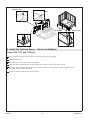
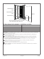
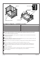
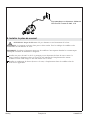
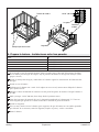
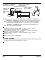
6. Install the Optional Apron – Alcove Installations
Series 7726, 7727, and 7728 Only
Place a protective barrier on the floor so the bath will not be scratched.
Turn the bath over.
Determine the correct side for the installation.
Align the three alignment tabs on the apron frame with the slots on the bath rim (1).
Press the alignment tabs into the slots on the bath rim. If necessary, gently tap the alignment tabs
into place using a rubber mallet (2).
Install the apron panels into the apron frame.
1
2
Slot
Alignment Tab
Apron Panel
Apron Frame
Sterling 11 1139487-2-H

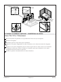
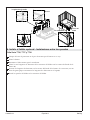
7. Prepare the Bath – Drop-In Installations
NOTICE: Do not allow the deck to support the bath by the rim. The bath must be supported by its feet.
Recessed Installation
NOTE: A recessed installation requires a cutout in the floor with decking on all four sides. A framework
and subfloor must be added below the deck. The deck positions the bath while the framework and
subfloor supports the bath.
Carefully lay out and cut the rough deck material, allowing the width and length of the opening to
be 1″ (25 mm) smaller than the bath. Refer to the applicable diagram in the ″Roughing-In″ section.
Allow clearance to install the drain assembly and the water supply piping.
Construct an 18″ (457 mm) x 15″ (381 mm) access panel at the blower end of the fixture.
Construct a level subfloor no lower than 18-3/4″ (476 mm) below the rough deck.
Construct the 2x4 or 2x6 framework on top of the level subfloor. The finished deck should allow
1/16″ (2 mm) clearance for sealant between the rough deck and the lower rim of the bath.
Island Installation
NOTE: An island installation requires a built-up, four-sided surround typically made of brick or concrete.
The surround positions the bath while the floor supports the bath.
Carefully lay out the masonry work. Consider whether the finished tile will be flush with the bath
or installed under the rim.
Allow clearance to install the drain assembly and the water supply piping.
Construct an 18″ (457 mm) x 15″ (381 mm) access panel at the blower end of the fixture.
Construct a level subfloor no lower than 18-3/4″ (476 mm) below the masonry island.
Construct the island of brick or concrete.
Add tile or other finishing material, leaving a 1/16″ (2 mm) clearance for sealant between the island
and the rim of the bath.
All Drop-in Installations
If a mortar cement bed was not installed, place a pad (not provided) with a cut drain hole on the
subfloor, then secure the felt pad into place with fasteners (such as staples or nails).
Verify that the bath is level. If the bath is not level, insert shims under the bath to adjust for level.
Island Installation
Construct opening to be 1" (25 mm)
smaller than the bath in both directions.
Construct according to
the rough-in illustration.
Recessed Installation
18-3/4" (476 mm) Max
18-3/4" (476 mm) Max
1/16"
(2 mm) Gap
1/16"
(2 mm) Gap
1139487-2-H 12 Sterling

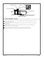
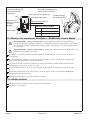
8. Install the Electrical Outlet
CAUTION: Risk of personal injury. Do not turn on the power until instructed to do so.
NOTE: The bath is equipped with a cord and plug. All blower and control wiring has been completed at
the factory.
NOTE: Refer to the label near the blower. This label identifies the electrical rating and model number of
the bath.
Install a GFCI-protected, 120 V, 15 A grounded outlet behind the bath and within 24″ (610 mm) of
the location of the blower. No other load should be on this circuit.
Install a bonding (grounding) conductor at the future location of the blower in accordance with any
applicable local codes.
GFCI-protected 120 V, 15 A grounded outlet
Sterling 13 1139487-2-H

9. Position the Bath
Alcove Installations
CAUTION: Risk of product damage. Do not lift or move the bath by the apron or apron braces. Verify
that the apron braces are attached before installing the bath, then lift the bath by the rim at multiple
points.
NOTE: 6’ (1.8 m) bath models require construction of an apron for alcove installations.
Verify that the bath is level.
With the apron braces attached, lift the bath into position. Position the bath so the outside edge is
flush with the framing.
Drop-In Installations (not shown)
With the drain and overflow assembly attached to the bath, lift the bath in the recess or island.
Verify that the bath is level and there is a 1/16″ (2 mm) gap between the rough deck or island and
bath rim.
NOTE: To adjust for level: Remove the bath. Place shims under the bath feet. Position the bath in the
recess or island and recheck for level. Repeat until the bath is level.
NOTE: The maximum distance between shimmed feet is 22″ (559 mm).
Shim if necessary.
Studs
Verify level.
1139487-2-H 14 Sterling

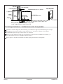
10. Secure the Bath – Alcove
Refer to the ″Roughing-In″ section for recommended clip locations.
Verify the studs are within 1/8″ (3 mm) of the bath at the recommended support clip locations.
Shim if necessary.
Slide the bottom of each attachment clip into the space between the bath flange and stud until the
tab touches the bath.
Secure the attachment clips with galvanized or plated flathead screws.
Subfloor
8-3/4" (222 mm) for series 7726, 7727 and 7728
11-3/4" (298 mm) for series 7730 and 7731
5-1/4" (133 mm) for series 7726, 7727 and 7728
5-15/16" (151 mm) for series 7730 and 7731
Attachment Clip
Ledger Strip
Stud Wall
Attachment Clip
Ø 2" (51 mm)
Drain
18-3/4"
(476 mm)
3/16"
(5 mm)
Flange
Ø 2-1/2" (64 mm) Overflow
17" (432 mm)
Overflow Height
Tab
Sterling 15 1139487-2-H

11. Secure the Bath – Drop-In
Verify that the studs are within 1/8″ (3 mm) of the bath at the recommended support clip or screw
locations. Shim if necessary.
Position the bottom lip of the attachment clip under the edge of the bath and place the tab against
the bath flange.
Drill pilot holes through the flange at the attachment clip locations to protect the flange from
cracking when the fasteners are installed.
Slide the attachment clip into place between the center of the stud and the bath.
Secure the attachment clips with galvanized or plated non-tapered flathead screws.
5-1/4" (133 mm) for series 7726, 7727 and 7728
5-15/16" (135 mm) for series 7730 and 7731
Attachment Clip
Screw
Attachment Clip
Flange
Flange
3/4" (19 mm) Plywood
Section at Drain End
Ø 2" (51 mm)
Drain
18-3/4"
(476 mm)
17"
(432 mm)
Ø 2-1/2" (64 mm) Overflow
16-1/2" (419 mm)
13/16" (21 mm)
1139487-2-H 16 Sterling

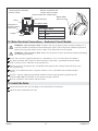
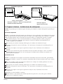
12. Make Electrical Connections - Dedicated Circuit Models
WARNING: Risk of electric shock. To reduce the risk of electrical shock, connect the blower to a
properly installed Ground-Fault Circuit-Interrupter (GFCI). This will provide additional protection
against line-to-ground shock hazard. A 120 V, 15 A dedicated circuit is required.
WARNING: Risk of electric shock. Make sure the power has been disconnected before performing
the following procedures.
Locate and secure the supplied junction box a minimum of 1-1/2″ (38 mm) above the subfloor.
The blower controls and system have been prewired at the factory. A qualified electrician should
make a routine service connection to the junction box.
Connect service to the junction box. The 60 Hz model junction box contains black and white wires
and a ground lug.
A 120 V, 15 A dedicated circuit is required. Provide a Class A Ground-Fault Circuit-Interrupter
(GFCI).
Provide a separate equipment grounding conductor for the inside ground or ground lug. The
conductor must not be connected to any current-carrying conductor.
Bond in accordance with national and local codes.
13. Install the Drain
Connect the drain to the trap according to the manufacturer’s instructions.
Check the drain connections for leaks.
The junction box should be
wired as shown
Bond in accordance with
national and local codes
Black
Supply
White
Electrician to
provide suitable
strain relief
Blower Motor
Electrical Cord
Ground (Green with Yellow Stripe)
Wire Connectors
From Blower Motor
From Blower Motor
L1
Black
N White
GND
Green with Yellow Stripe
Sterling 17 1139487-2-H

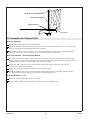
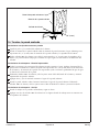
14. Complete the Finished Wall
Alcove Installations
Brush all dust and debris from the bath flange.
Install the finished wall material over the water-resistant wall material. Maintain a 1/8″ (3 mm) gap
between the finished wall material and the bath surface.
Using 100% silicone sealant, seal the 1/8″ (3 mm) gap between the bath surface and finished wall.
Allow the sealant to cure according to the sealant manufacturer’s instructions.
Drop-In Installations – Water-Resistant Material
Cover the framing with water-resistant wall/deck material. Apply the wall material over the bath
flange, leaving a 1/16″ (2 mm) gap between the bath rim edge and the wall material. This gap helps
to reduce the possibility of water seeping into the wall material.
Using clear 100% silicone sealant, seal the joints between the edge of the bath rim and the
water-resistant wall/deck material.
Apply tape and mud to the water-resistant wall/deck material.
Install the finished wall over the water-resistant wall/deck material. Using 100% silicone sealant,
seal the joints between the edge of the bath rim and the finished wall.
Drop-In Installations – Tile
Install tile to the surrounding walls, as desired.
Apply a bead of 100% silicone sealant where the tile meets the bath surface.
Finished Wall Material
Silicone Sealant
Water-Resistant Wall Material
1/8" (3 mm)
1139487-2-H 18 Sterling

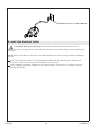
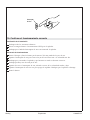
15. Confirm Proper Operation
Installation Checkout
Verify all electrical connections.
Turn on the power to the GFCI outlet for the blower.
Verify the tubing from the air switch is connected to the blower.
Operating Sequence
Close the drain and fill the bath to at least 2″ (51 mm) above the airjets.
Press the air switch to activate the airjets. Air will flow at its highest speed.
Verify that the blower starts and operates without excessive noise or vibration.
Verify that air is flowing from each airjet.
Press the air switch twice, cycling through the medium and low speeds.
Press the air switch again to turn off the blower. Verify that the blower stops.
Drain the bath.
Air Switch
Sterling 19 1139487-2-H
Page is loading ...
Page is loading ...
Page is loading ...
Page is loading ...
Page is loading ...
Page is loading ...
Page is loading ...
Page is loading ...
Page is loading ...
Page is loading ...
Page is loading ...
Page is loading ...
Page is loading ...
Page is loading ...
Page is loading ...
Page is loading ...
Page is loading ...
Page is loading ...
Page is loading ...
Page is loading ...
Page is loading ...
Page is loading ...
Page is loading ...
Page is loading ...
Page is loading ...
Page is loading ...
Page is loading ...
Page is loading ...
Page is loading ...
Page is loading ...
Page is loading ...
Page is loading ...
Page is loading ...
Page is loading ...
Page is loading ...
Page is loading ...
Page is loading ...
Page is loading ...
Page is loading ...
Page is loading ...

USA: 1-800-STERLING
(1-800-783-7546)
México: 001-877-680-1310
SterlingPlumbing.com
©2012 Kohler Co.
1139487-2-H
-
 1
1
-
 2
2
-
 3
3
-
 4
4
-
 5
5
-
 6
6
-
 7
7
-
 8
8
-
 9
9
-
 10
10
-
 11
11
-
 12
12
-
 13
13
-
 14
14
-
 15
15
-
 16
16
-
 17
17
-
 18
18
-
 19
19
-
 20
20
-
 21
21
-
 22
22
-
 23
23
-
 24
24
-
 25
25
-
 26
26
-
 27
27
-
 28
28
-
 29
29
-
 30
30
-
 31
31
-
 32
32
-
 33
33
-
 34
34
-
 35
35
-
 36
36
-
 37
37
-
 38
38
-
 39
39
-
 40
40
-
 41
41
-
 42
42
-
 43
43
-
 44
44
-
 45
45
-
 46
46
-
 47
47
-
 48
48
-
 49
49
-
 50
50
-
 51
51
-
 52
52
-
 53
53
-
 54
54
-
 55
55
-
 56
56
-
 57
57
-
 58
58
-
 59
59
-
 60
60


Ask a question and I''ll find the answer in the document
Finding information in a document is now easier with AI
in other languages
- français: Sterling 77311100-0 Guide d'installation
- español: Sterling 77311100-0 Guía de instalación
Related papers
-
Sterling 77281100-96 Installation guide
-
-
-
Sterling 95081-0 Installation guide
-
-
-
Sterling 72240106-0 Installation guide
-
-
-
Other documents
-
Kohler 877-96 Installation guide
-
Sterling Plumbing Hot Tub 7104 Series User manual
-
Kohler 710-W-0 Installation guide
-
-
Keeney KIT-QUA130CMB Installation guide
-
-
-
-
-
Kohler K-700-96 Installation guide