Page is loading ...

SALON™ SPA
AIR BATH AND WHIRLPOOL
INSTALLATION AND OPERATING INSTRUCTIONS
©2006 Jacuzzi Whirlpool Bath EL21000B 10/06
Installer: Leave this manual for homeowner.
Homeowner: Read this manual and keep for future reference.
Owner's Record
Save These Instructions for Future Use.
Complete and mail-in the product registration card provided with your unit.
Write and save the model and serial number of your unit below.
Date Purchased ____________________________________________________________
Purchased From ____________________________________________________________
Installed By ________________________________________________________________
Serial Number ______________________________________________________________
Model _____________________________________________________________________

ENGLISH
IMPORTANT SAFETY INSTRUCTIONS
READ AND FOLLOW ALL INSTRUCTIONS
SAVE THESE INSTRUCTIONS
INSTRUCTIONS PERTAINING TO A RISK OF FIRE, ELECTRIC
SHOCK, OR INJURY TO PERSONS
WARNING — WHEN USING THIS UNIT, BASIC PRECAUTIONS SHOULD ALWAYS BE FOLLOWED,
INCLUDING THE FOLLOWING:
DANGER: — TO REDUCE THE RISK OF INJURY, DO NOT PERMIT CHILDREN TO USE THIS UNIT
UNLESS THEY ARE CLOSELY SUPERVISED AT ALL TIMES.
WARNING — USE THIS UNIT ONLY FOR ITS INTENDED USE AS DESCRIBED IN THIS MANUAL. DO
NOT USE ATTACHMENTS NOT RECOMMENDED BY THE MANUFACTURER.
WARNING — NEVER DROP OR INSERT ANY OBJECT INTO ANY OPENING.
WARNING — DO NOT OPERATE THIS UNIT WITHOUT THE GUARD OVER THE INTAKE FOR THE
CIRCULATION PUMP (SUCTION COVER/STRAINER).
WARNING — THIS UNIT MUST BE CONNECTED ONLY TO A SUPPLY CIRCUIT THAT IS PROTECTED
BY A GROUND FAULT CIRCUIT INTERRUPTER (GFCI). SUCH A GFCI SHOULD BE PROVIDED BY THE
INSTALLER AND SHOULD BE TESTED ON A ROUTINE BASIS. TO TEST THE GFCI, PUSH THE TEST
BUTTON. THE GFCI SHOULD INTERRUPT POWER. PUSH THE RESET BUTTON. POWER SHOULD
BE RESTORED. IF THE GFCI FAILS TO OPERATE IN THIS MANNER, THE GFCI IS DEFECTIVE. IF
THE GFCI INTERRUPTS POWER TO THE BATHTUB WITHOUT THE TEST BUTTON BEING PUSHED,
A GROUND CURRENT FLOWING, INDICATING A POSSIBILITY OF AN ELECTRIC SHOCK. DO NOT
USE THIS HYDROMASSAGE BATHTUB. DISCONNECT THE HYDROMASSAGE BATHTUB AND HAVE
THE PROBLEM CORRECTED BY A QUALIFIED SERVICE REPRESENTATIVE BEFORE USING.
WARNING — (FOR PERMANENTLY CONNECTED UNITS) A GREEN COLORED TERMINAL (OR A
WIRE CONNECTOR MARKED “G”, “GR”, “GROUND”, OR “GROUNDING”) IS PROVIDED WITHIN
THE TERMINAL COMPARTMENT. TO REDUCE THE RISK OF ELECTRIC SHOCK, CONNECT THE
TERMINAL OR CONNECTOR TO THE GROUNDING TERMINAL OF YOUR ELECTRIC SERVICE
OR SUPPLY PANEL WITH A CONDUCTOR EQUIVALENT IN SIZE TO THE CIRCUIT CONDUCTORS
SUPPLYING THIS EQUIPMENT.
OPERATING
WARNING — PROLONGED IMMERSION IN HOT WATER MAY INDUCE HYPERTHERMIA. HYPER-
THERMIA OCCURS WHEN THE INTERNAL TEMPERATURE OF THE BODY REACHES A LEVEL
SEVERAL DEGREES ABOVE THE NORMAL BODY TEMPERATURE OF 98.6°F. THE SYMPTOMS OF
HYPERTHERMIA INCLUDE AN INCREASE IN THE INTERNAL TEMPERATURE OF THE BODY, DIZZI-
NESS, LETHARGY, DROWSINESS AND FAINTING. THE EFFECTS OF HYPERTHERMIA INCLUDE:
A) FAILURE TO PERCEIVE HEAT
B) FAILURE TO RECOGNIZE THE NEED TO EXIT THE SPA OR HOT TUB,
C) UNAWARENESS OF IMPENDING HAZARD,
D) FETAL DAMAGE IN PREGNANT WOMEN,
E) PHYSICAL INABILITY TO EXIT THE SPA OR HOT TUB, AND
F) UNCONSCIOUSNESS RESULTING IN DANGER OF DROWNING.
WARNING — THE USE OF ALCOHOL, DRUGS OR MEDICATION CAN GREATLY INCREASE THE
RISK OF FATAL HYPERTHERMIA.
WARNING — DO NOT TAMPER WITH USER-OPERATED CONTROLS OR SUCH DEVICES.
2
Jacuzzi Whirlpool Bath EL21000B 10/06

ENGLISH
PRODUCT SPECIFICATIONS ARE SUBJECT TO CHANGE WITHOUT NOTICE.
USE INSTALLATION INSTRUCTIONS SUPPLIED WITH PRODUCT.
The Company has obtained applicable code (standards) listings generally available on a national basis for products of this type.
It is the responsibility of the installer/owner to determine specifi c local code compliance prior to installation of the product. The
Company makes no representation or warranty regarding, and will not be responsible for any code compliance.
NOTE: This is a professional grade product. A knowledge of construction techniques, plumbing and electri-
cal installation according to codes are required for proper installation and user satisfaction. We recommend
that a licensed contractor perform the installation of all Jacuzzi Whirlpool Bath products. Our warranty does
not cover improper installation related problems.
PRECAUTIONS
! Do not operate the hydromassage system unless the bath is fi lled with water to at least 1" to 2" (25,4 - 50,8 mm) above
the highest jet.
! Do not immerse the control panel by overfi lling the bath.
! Do not use oil-based bath additives in your hydromassage bath.
! When cleaning your bath, do not use abrasive substances which will damage the bath's surface.
! To prevent discoloration of the acrylic fi nish, do not fi ll the bath with water in excess of 140°F (60°C).
WARNING — WHEN USING THIS UNIT, BASIC PRECAUTIONS SHOULD ALWAYS BE FOLLOWED, IN-
CLUDING THE FOLLOWING:
DANGER — RISK OF ELECTRIC SHOCK. CONNECT ONLY TO A CIRCUIT PROTECTED BY A GROUND
FAULT CIRCUIT INTERRUPTER (GFCI).
CAUTION — TEST THE GROUND FAULT CIRCUIT INTERRUPTER PROTECTING THIS APPLIANCE PE-
RIODICALLY IN ACCORDANCE WITH MANUFACTURER’S INSTRUCTIONS.
WARNING — USE THIS UNIT ONLY FOR ITS INTENDED USE AS DESCRIBED IN THIS MANUAL. DO NOT
USE ATTACHMENTS NOT RECOMMENDED BY THE MANUFACTURERS.
WARNING — TO AVOID INJURY, EXERCISE CAUTION WHEN ENTERING OR EXITING THE HYDROMAS-
SAGE BATHTUB.
WARNING — KEEP BODY AND HAIR A MINIMUM OF 6" (15,2 cm) AWAY FROM SUCTION FITTING AT
ALL TIMES WHEN THE HYDROMASSAGE SYSTEM IS OPERATING. HAIR LONGER THAN SHOULDER
LENGTH SHOULD BE SECURED CLOSE TO THE HEAD.
WARNING — RISK OF ELECTRICAL SHOCK; DO NOT PERMIT ELECTRICAL APPLIANCES (SUCH AS
HAIR DRYER, LAMP, TELEPHONE, RADIO OR TELEVISION) WITHIN 60" (1,5 m) OF THIS HYDROMAS-
SAGE BATHTUB.
WARNING — RISK OF ACCIDENTAL INJURY OR DROWNING; DO NOT USE DRUGS OR ALCOHOL BE-
FORE OR DURING THE USE OF HYDROMASSAGE BATHTUB EQUIPPED WITH A HEATER TO AVOID
UNCONSCIOUSNESS AND POSSIBLE DROWNING.
WARNING — RISK OF FETAL INJURY; PREGNANT OR POSSIBLY PREGNANT WOMEN SHOULD CON-
SULT A PHYSICIAN BEFORE USING A HYDROMASSAGE BATHTUB EQUIPPED WITH A HEATER.
WARNING — RISK OF HYPERTHERMIA AND POSSIBLE DROWNING; DO NOT USE A HYDROMASSAGE
BATHTUB EQUIPPED WITH A HEATER IMMEDIATELY FOLLOWING STRENUOUS EXERCISE.
WARNING — RISK OF HYPERTHERMIA AND POSSIBLE DROWNING; WATER TEMPERATURE IN EXCESS
OF 104°F (40°C) MAY BE INJURIOUS TO YOUR HEALTH. CHECK AND ADJUST WATER TEMPERATURE
BEFORE USE.
WARNING — RISK OF HYPERTHERMIA; PEOPLE USING MEDICATIONS AND/OR HAVING AN ADVERSE
MEDICAL HISTORY SHOULD CONSULT A PHYSICIAN BEFORE USING A HYDROMASSAGE BATHTUB
EQUIPPED WITH A HEATER.
FOR BUILT-IN AND DROP-IN UNITS, INSTALL TO PERMIT ACCESS FOR SERVICING.
THIS UNIT SHOULD BE ELECTRICALLY GROUNDED AND INSTALLED BY A LICENSED CONTRACTOR,
ELECTRICIAN, AND PLUMBER.
BUILDING MATERIALS AND WIRING SHOULD BE ROUTED AWAY FROM THE MOTOR/PUMP OR
BLOWER OR OTHER HEAT PRODUCING COMPONENTS OF THIS UNIT.
A PRESSURE WIRE CONNECTOR IS PROVIDED ON THE EXTERIOR OF THE MOTOR/PUMP AND
HEATER TO PERMIT CONNECTION OF AN NO. 8 AWG (8.4 mm) SOLID COPPER BONDING CONDUCTOR
BETWEEN THIS UNIT AND ALL OTHER ELECTRIC EQUIPMENT AND EXPOSED METAL IN THE VICINITY,
AS NEEDED TO COMPLY WITH LOCAL REQUIREMENTS.
SAFETY INSTRUCTIONS - INSTALLATION
3
Jacuzzi Whirlpool Bath EL21000B 10/06

ENGLISH
CONTENTS
Safety Instruction ______________________________________________________________________ 2-3
Contents _____________________________________________________________________________ 4
Specifi cations _________________________________________________________________________ 5-8
Roughing-in Reference __________________________________________________________________ 9-12
Framing and Support ___________________________________________________________________ 13
Service Access ________________________________________________________________________ 13
Electrical Connections ___________________________________________________________________ 14-15
Fuzion control Panel Installation ___________________________________________________________ 15
Plumbing and Water Supply ______________________________________________________________ 16
Fuzion Overfl ow Installation ______________________________________________________________ 16
Clean Up After Installation _______________________________________________________________ 16
Operating Instructions __________________________________________________________________ 17-21
Salon Control Panel __________________________________________________________________ 18-19
Salon Control Panels (for Mito™ 6) ______________________________________________________ 20
Maintenance Instructions _________________________________________________________________ 22-23
General Troubleshooting Guide ____________________________________________________________ 24
Authorized Service _____________________________________________________________________ 25
Warranty _____________________________________________________________________________ 27-28
NOTE: To obtain a referral for a service agent in your area call 1-800-288-4002. You may also visit our web site at
http://www.jacuzzi.com/. To fi nd service agent listings for:
Electrical or Mechanical Repairs visit http://jacuzzi.com/pdf/ASA.PDF
Finish, Surface, or Shell-Related Repairs visit http://jacuzzi.com/pdf/AFC.PDF
Repair Parts or Accessories visit http://jacuzzi.com/pdf/MPD.PDF
4
Jacuzzi Whirlpool Bath EL21000B 10/06

ENGLISH
SPECIFICATIONS
Important: Read complete instructions before beginning installation.
Each bath arrives ready for installation, completely equipped with blower motor, pump/motor assembly, heater, and plumbing
necessary for operation.
Remove the bath from the carton. Retain the shipping carton until satisfactory inspection of the product has been made. Do
not lift the bath by the plumbing or wiring at any time; handle by the shell only.
Immediately upon receipt, inspect the shell before installing. Should inspection reveal any damage or defect in the fi nish,
do not install the bath. Damage or defect to the fi nish claimed after the bath is installed is excluded from the warranty. Jacuzzi
Whirlpool Bath's responsibility for shipping damage ceases upon delivery of the products in good order to the carrier. Refer any
claims for damage to the carrier. For defi nitions of warranty coverage and limitations, refer to the published warranty information
packed with the product.
All bath units are factory tested for proper operation and watertight connections prior to shipping. NOTE: Prior to installa-
tion, the bath must be fi lled with water and operated to check for leaks that may have resulted from shipping damage
or mishandling. Jacuzzi Whirlpool Bath is not responsible for any defect that could have been discovered, repaired, or avoided
by following this inspection and testing procedure.
DRAIN/OVERFLOW
A
B
RECTANGULAR BATHS
5
Jacuzzi Whirlpool Bath EL21000B 10/06
END VIEW
SIDE VIEW
2"
(Inlet Heater)
(Motor)
(51 mm)
(Blower)
L
W
H
BELLAVISTA™
END VIEW
H
W
SIDE VIEW
L
1/2"
(13 mm)
(Motor)
(Inlet Heater)
(Blower)
ELARA
B
A
FUZION™
DRAIN/OVERFLOW
72"
26-1/2"
2"
1"
47"
SIDE VIEW
END VIEW
(51 mm)
(Inlet Heater)
(Motor)
(Blower)
(25 mm
SABELLA™
END VIEW
25"
42
"
SIDE VIEW
72
"
2"
(51 mm)
(Inlet Heater)
(Motor)
(Blower)
REÁL™
(
133 mm
)
5-1/4"
SIDE VIEW END VIEW
70-11/16"
(Motor)
(Inlet Heater)
25-1/4"
35-3/8"
(Blower)
FUZION™ 7236 with wood
SIDE VIEW END VIEW
(Motor)
(Inlet Heater)
24"
(
102 mm
)
4"
(Blower)
70-11/16"
35-3/8"
FUZION™ 7236 undermount
6-1/4" (159 mm)
SIDE VIEWEND VIEW
(Motor)
(Inlet Heater)
72"
25-1/4"
60"
(Blower)
FUZION™ 7260 with wood
SIDE VIEWEND VIEW
(Motor)
(Inlet Heater)
72"
24"
60"
5" (127 mm)
(Blower)
FUZION™ 7260 undermount
END VIEW
SIDE VIEW
72"
2"
(51 mm)
(Heater Blank)*
42"
21-1/2"
(Blower)
(Motor)
MITO™ 6
*MITO™ 6 COMES WITH HEATER BLANK ONLY.
INLINE HEATER MUST BE PURCHASED SEPARATELY.

ENGLISH
SPECIFICATIONS
(Rectangular) RH = RIGHT HAND
NOTE: The overall dimensions are nominal with a tolerance of +0 and -1/4" (6,4 mm).
FOR MITO™ UNIT: Electrical Service Requirements: It requires a dedicated GFCI protected separate circuit.
Blower and Motor/Pump: 120 VAC, 20 AMP, 60 Hz. dedicated GFCI protected separate circuit.
BELLAVISTA™
6
RH
BELLAVISTA™
5
RH
BELLAVISTA™
5.5
RH
72” (1829 mm) L
42” (1067 mm) W
26” ( 660 mm) H
60” (1524 mm) L
42” (1067 mm) W
26” ( 660 mm) H
66” (1676 mm) L
42” (1067 mm) W
26” ( 660 mm) H
Not Available
Not Available
180 lb
(81.8 kg)
157 lb
(71.3 kg)
85 U.S. gal
(322 liters)
177 lb
(80.5 kg)
Not Available
1025 lb
(466 kg)/
59 lb/ft
2
(287 kg/m
2
)
1186 lb
(539 kg)/
61.57 lb/ft
2
(299.8 kg/m
2
)
1231 lb
(560 kg)/
59 lb/ft
2
(228 kg/m
2
)
20” (508 mm) A
11-3/4” (298 mm) B
20” (508 mm) A
11-3/4” (298 mm) B
20” (508 mm) A
11-3/4” (298 mm) B
Template
Provided
P/N
P187000
Template
Provided
P/N
P187000
Template
Provided
P/N
P187000
Factory Installed
(BN60000 HEATER 230V)
MODEL
PRODUCT
WEIGHT
OPERATING
GALLONAGE
TOTAL WEIGHT/
FLOOR LOADINGDIMENSIONS DRAIN/OVERFLOW
SKIRT &
MOUNTINGCUTOUT
HEATER
Factory Installed
(BN60000 HEATER 230V)
Factory Installed
(BN60000 HEATER 230V)
6
Jacuzzi Whirlpool Bath EL21000B 10/06
ELARA™ 6636
RH
ELARA™ 6042
RH
66” (1676 mm) L
36” ( 914 mm) W
26” ( 660 mm) H
60” (1524 mm) L
42” (1067 mm) W
26” ( 660 mm) H
Not Available
164 lb
(74.5 kg)
170 lb
(77 kg)
Not Available
942 lb
(428 kg)/
53.8 lb/ft
2
(262 kg/m
2
)
847 lb
(385 kg)/
51.3 lb/ft
2
(250 kg/m
2
)
18-1/2” (470 mm) A
9.6” (269 mm) B
18-1/2” (470 mm) A
9.6” (269 mm) B
58” x 40”
(1473 mm x 1016
mm)
Umt Template
Provided
P/N DQ50000
64” x 34”
(1626 mm x 864
mm)
Umt Template
Provided
P/N DQ51000
Factory Installed
(BN60000 HEATER 230V)
Factory Installed
(BN60000 HEATER 230V)
ELARA™ 7242
RH
72” (1829 mm) L
42” (1067 mm) W
26” ( 660 mm) H
Not Available178 lb
(81 kg)
1060 lb
(482 kg)/
50.5 lb/ft
2
(246 kg/m
2
)
18-1/2” (470 mm) A
9.6” (269 mm) B
70” x 40”
(1778 mm x 1016
mm)
Umt Template
Provided
P/N BZ50000
Factory Installed
(BN60000 HEATER 230V)
SABELLA™
RH
REÁL™
RH
72” (1829 mm) L
47” (1194 mm) W
26-1/2” ( 673 mm) H
72” (1829 mm) L†
42” (1067 mm) W
26” ( 660 mm) H
Not Available179 lb
(81.4 kg)
Not Available
1230 lb
(559 kg)/
58.83 lb/ft
2
(287 kg/m
2
)
1302 lb
(592 kg)/
55.3 lb/ft
2
(269 kg/m
2
)
20 “ (508 mm) A
14 “ (356 mm) B
20 “ (508 mm) A
14” (356 mm) B
70” x 40”
(1778 mm x
1016 mm)
Template
Provided
P/N
P187000
Factory Installed
(BN60000 HEATER 230V)
Factory Installed
(BN60000 HEATER 230V)
FUZION™ 7260
WITH TEAK or
WENGE
RH
FUZION™ 7236
WITH TEAK or
WENGE
RH
FUZION™ 7236
UNDERMOUNT
RH
72” (1829 mm) L
60” (1524 mm) W
25-1/4” ( 641 mm) H
70-11/16” (1795 mm) L
35-3/8” ( 899 mm) W
25-1/4” ( 641 mm) H
70-11/16” (1795 mm) L
35-3/8” ( 899 mm) W
24” ( 610 mm) H
Not Available
Not Available
Min - 145 U.S. gal
(549 liters)
Max - 192 U.S. gal
(727 liters)
274 lb
(125 kg)
Min - 70 U.S. gal
(265 liters)
Max - 94 U.S. gal
(360 liters)
200 lb
(75 kg)
Min - 70 U.S. gal
(265 liters)
Max - 94 U.S. gal
(360 liters)
165 lb
(75 kg)
Not Available
1180 lb
(536 kg)/
65.6 lb/ft
2
(319 kg/m
2
)
1145 lb
(520.4 kg)/
63.7 lb/ft
2
(310 kg/m
2
)
1805 lb
(820 kg)/
60 lb/ft
2
(292 kg/m
2
)
16-3/4” (425 mm) A
12-1/16” (306 mm) B
17” (432 mm) A
10-1/4” (260 mm) B
17” (432 mm) A
10-1/4” (260 mm) B
69-1/2” x
34-3/8”
(1765 mm x
873 mm)
Template
Provided
P/N
DD42000
71” x 59”
(1803 mm x
1499 mm)
Factory Installed
(BN60000 HEATER 230V)
Factory Installed
(BN60000 HEATER 230V)
Factory Installed
(BN60000 HEATER 230V)
FUZION™ 7260
UNDERMOUNT
RH
72” (1829 mm) L
60” (1524 mm) W
24” ( 610 mm) H
Min - 145 U.S. gal
(549 liters)
Max - 192 U.S. gal
(727 liters)
199 lb
(90.5 kg)
Not Available1730 lb
(786 kg)/
57.6 lb/ft
2
(280.5 kg/m
2
)
16-3/4” (425 mm) A
12-1/16” (306 mm) B
Template
Provided
P/N
DD44000
Factory Installed
(BN60000 HEATER 230V)
SPECIFICATIONS
90 U.S. gal
(341 liters)
80 U.S. gal
(303 liters)
Min - 75 U.S. gal
(284 liters)
Max - 83 U.S. gal
(314 liters)
Min - 83 U.S. gal
(314 liters)
Max - 92 U.S. gal
(348 liters)
Min - 95 U.S. gal
(360 liters)
Max - 105 U.S. gal
(398 liters)
98 U.S. gal
(371 liters)
184 lb
(84 kg)
MITO™ 6
RH
72” (1829 mm) L
42” (1067 mm) W
21-1/2” ( 546 mm) H
Not Available155 lb
(70.5 kg)
1197 lb
(544 kg)/
57 lb/ft
2
(278 kg/m
2
)
17-1/2” (445 mm) A
11-7/8” (302 mm) B
70” x 40”
(1778 mm x
1016 mm)
HEATER READY FOR FIELD
INSTALLATION
(S750000 HEATER 120V KIT)
Min - 62 U.S. gal
(235 liters)
Max - 90 U.S. gal
(341 liters)
Min - 62 U.S. gal
(235 liters)
Max - 90 U.S. gal
(341 liters)
† Add 1/4” (6,4 mm) to this dimension when roughing-in for 3-wall niche.
NOTE: The overall dimensions are nominal with a tolerance of +0 and -1/4" (6,4 mm).
FOR ALL UNITS: Electrical Service Requirements: All require a dedicated GFCI protected separate circuit.
Blower: 120 VAC, 20 AMP, 60 Hz. dedicated GFCI protected separate circuit.
Motor/Pump and RapidHeat™: 240 VAC, 20 AMP, 60 Hz. dedicated GFCI protected separate circuit.

ENGLISH
7
Jacuzzi Whirlpool Bath EL21000B 10/06
SPECIFICATIONS (Oval and Round) RH = RIGHT HAND
NOTE: The overall dimensions are nominal with a tolerance of +0 and -1/4" (6,4 mm).
FOR ALL UNITS: Electrical Service Requirements: All require a dedicated GFCI protected separate circuit.
Blower: 120 VAC, 20 AMP, 60 Hz. dedicated GFCI protected separate circuit.
Motor/Pump and RapidHeat™: 240 VAC, 20 AMP, 60 Hz. dedicated GFCI protected separate circuit.
DUETTA™ 6636
RH
DUETTA™ 6042
RH
66” (1676 mm) L
36” ( 914 mm) W
26” ( 660 mm) H
60” (1524 mm) L
42” (1067 mm) W
26” ( 660 mm) H
Not Available
160 lb
(72.7 kg)
110 lb
(50 kg)
Not Available
999 lb
(454 kg)/
57.1 lb/ft
2
(278 kg/m
2
)
1027 lb
(467 kg)/
62.3 lb/ft
2
(303 kg/m
2
)
18.4” (467 mm) A
11” (279 mm) B
18.4” (467 mm) A
11” (279 mm) B
Template
Provided
P/N
DA09000
Template
Provided
P/N
DA08000
MODEL
PRODUCT
WEIGHT
OPERATING
GALLONAGE
TOTAL WEIGHT/
FLOOR LOADINGDIMENSIONS DRAIN/OVERFLOW
SKIRT &
MOUNTINGCUTOUT
HEATER
Factory Installed
(BN60000 HEATER 230V)
Factory Installed
(BN60000 HEATER 230V)
DRAIN/OVERFLOW
A
B
OVAL AND ROUND BATHS
VENICIA™
RH
DUETTA™ 6642
RH
DUETTA™ 7242
RH
72” (1829 mm) L
42” (1067 mm) W
26” ( 660 mm) H
66” (1676 mm) L
42” (1067 mm) W
26” ( 660 mm) H
72” (1829 mm) L
42” (1067 mm) W
26” ( 660 mm) H
Not Available
Not Available
90 U.S. gal
(341 liters)
179 lb
(81.4 kg)
117 lb
(53 kg)
130 lb
(59 kg)
Not Available
1106 lb
(503 kg)/
57.5 lb/ft
2
(280 kg/m
2
)
1277 lb
(580.5 kg)/
60.8 lb/ft
2
(296 kg/m
2
)
1230 lb
(559 kg)/
58.83 lb/ft
2
(287 kg/m
2
)
20” (508 mm) A
14” (356 mm) B
18.4” (467 mm) A
11” (279 mm) B
18.4” (467 mm) A
11” (279 mm) B
Template
Provided
P/N
DA07000
Template
Provided
P/N
DA06000
Template
Provided
P/N
P187000
Factory Installed
(BN60000 HEATER 230V)
Factory Installed
(BN60000 HEATER 230V)
Factory Installed
(BN60000 HEATER 230V)
SPECIFICATIONS
END VIEW
H
W
SIDE VIEW
L
1/2"
(13 mm)
(Motor)
(Inlet Heater)
(Blower)
DUETTA
END VIEW
H
W
SIDE VIEW
2"
(Motor)
L
(51 mm)
VENICIA™
(Inlet Heater)
(Blower)
Min - 75 U.S. gal
(284 liters)
Max - 80 U.S. gal
(303 liters)
Min - 77 U.S. gal
(291 liters)
Max - 83 U.S. gal
(314 liters)
Min - 90 U.S. gal
(341 liters)
Max - 95 U.S. gal
(360 liters)
Min - 98 U.S. gal
(371 liters)
Max - 106 U.S. gal
(401 liters)

ENGLISH
8
Jacuzzi Whirlpool Bath EL21000B 10/06
SPECIFICATIONS (Corner) RH = RIGHT HAND
NOTE: The overall dimensions are nominal with a tolerance of +0 and -1/4" (6,4 mm).
FOR ALL UNITS: Electrical Service Requirements: All require a dedicated GFCI protected separate circuit.
Blower: 120 VAC, 20 AMP, 60 Hz. dedicated GFCI protected separate circuit.
Motor/Pump and RapidHeat™: 240 VAC, 20 AMP, 60 Hz. dedicated GFCI protected separate circuit.
FUZION™ 6666
UNDERMOUNT
RH
BELLAVISTA
CORNER
RH
FUZION™ 6666
WITH TEAK or
WENGE
RH
66” (1676 mm) L
66” (1676 mm) W
24” ( 610 mm) H
60” (1524 mm) L
60” (1524 mm) W
25” ( 635 mm) H
66” (1676 mm) L
66” (1676 mm) W
25-1/4” ( 641 mm) H
Not Available
Not Available
Min - 124 U.S. gal
(469 liters)
Max - 176 U.S. gal
(666 liters)
184 lb
(83.5 kg)
110 lb
(50 kg)
Min - 124 U.S. gal
(469 liters)
Max - 176 U.S. gal
(666 liters)
256 lb
(116.4 kg)
Not Available
1165 lb
(530 kg)/
49.6 lb/ft
2
(242 kg/m
2
)
1923 lb
(874 kg)/
72.6 lb/ft
2
(354 kg/m
2
)
1851 lb
(841 kg)/
69.8 lb/ft
2
(340 kg/m
2
)
16-13/16” (427 mm) A
12-1/8” (308 mm) B
18-7/8” (479 mm) A
14” (356 mm) B
16-13/16” (427 mm) A
12-1/8” (308 mm) B
Template
Provided
P/N
P654000
See
Page 12
Template
Provided
P/N
DD43000
Factory Installed
(BN60000 HEATER 230V)
MODEL
PRODUCT
WEIGHT
OPERATING
GALLONAGE
TOTAL WEIGHT/
FLOOR LOADINGDIMENSIONS DRAIN/OVERFLOW
SKIRT &
MOUNTINGCUTOUT
HEATER
Factory Installed
(BN60000 HEATER 230V)
Factory Installed
(BN60000 HEATER 230V)
CORNER BATHS
SPECIFICATIONS
(159 mm)
6-1/4"
SIDE VIEW END VIEW
DRAIN/OVERFLOW
B
A
(Intake Heater)
(Motor)
25-1/4"
66"
66"
(Blower)
FUZION™ 6666 with wood
25"
SIDE VIEW
A
B
DRAIN/OVERFLOW
(Inlet Heater)
(Motor)
(Blower)
60"
END VIEW
2”
(51 mm)
BELLAVISTA™ CORNER
SIDE VIEW END VIEW
DRAIN/OVERFLOW
B
A
(Inlet Heater)
(Motor)
24"
66"
(
127 mm
)
5"
66"
(Blower)
FUZION™ 6666 undermount
Min - 77 U.S. gal
(291 liters)
Max - 83 U.S. gal
(314 liters)

ENGLISH
9
Jacuzzi Whirlpool Bath EL21000B 10/06
ROUGHING-IN REFERENCE
NOTE: 1. THE OVERALL DIMENSIONS ARE NOMINAL WITH A TOLERANCE OF +0 AND -1/4" (6,4 mm).
2. Measurements inside each unit represent cutout in fl oor to allow for drain/overfl ow.
3. All measurements are in inches. To convert to millimeters, multiply inches by 25.4.
4. Service Access dimensions given are minimum size.
7"
32-1/2"
11-3/4"
6"
30-1/8"
42"
60"
4" x 4"
Motor
12" H x 24" L
Service Access
Heater
Blower
Bellavista™ 5,
(Right Hand Only)
10"
35-1/2"
11-3/4"
6"
30-1/8"
42"
66"
4" x 4"
Motor
12" H x 24" L
Service Access
Heater
Blower
Bellavista™ 5.5
(Right Hand Only)
4" x 4"*
42"
72"
10-1/2"
35-13/16"
11-3/4"
6"
30-1/8"
Motor
12" H x 24" L
Service Access
Heater
Blower
Bellavista™ 6
(Right Hand Only)
36"
42"
72"
11-7/8"
10" x 4"
2"
Motor
12" H x 24" L
Service Access
5-3/8"
Blower
Heater Blank*
MITO™ 6,
(Right hand only)
*MITO™ 6 COMES WITH HEATER BLANK ONLY.
INLINE HEATER MUST BE PURCHASED SEPARATELY.
60"
42"
21"
4.2"
9.6"
12" x 4"
2"
Heater
Motor
Opt. Service
Access
12" H x 24" L
Service Access
Blower
Elara™ 6042,
Right Hand
Elara™ 6636,
Right Hand
66"
36"
18 "
4.2"
9.6"
12" x 4"
Motor
Opt. Service
Access
12" H x 24" L
Service Access
Heater
2"
Blower
Some tubs are supplied with cutout template and/or undermount template. Refer to CUTOUT on pages 6-8 for template part
numbers.
72"
42"
21"
4.2"
9.6"
12" x 4"
2"
Heater
Motor
Opt. Service
Access
12" H x 24" L
Service Access
Blower
Elara™ 7242,
Right Hand

ENGLISH
10
Jacuzzi Whirlpool Bath EL21000B 10/06
ROUGHING-IN REFERENCE
NOTE: 1. THE OVERALL DIMENSIONS ARE NOMINAL WITH A TOLERANCE OF +0 AND -1/4" (6,4 mm).
2. Measurements inside each unit represent cutout in fl oor to allow for drain/overfl ow.
3. All measurements are in inches. To convert to millimeters, multiply inches by 25.4.
4. Service Access dimensions given are minimum size.
Motor
Opt. Service Access
17-11/16''
2''
7''
10-1/4''
12'' x 4"*
Heater
70-11/16''
35-3/8''
12" H x 24" L
Service Access
Blower
Fuzion™ 7236, Right Hand
Opt. Service Access
17-11/16''
2''
7''
10-1/4''
12'' x 4"*
Heater
70-11/16''
35-3/8''
Motor
12" H x 24" L
Service Access
Blower
Fuzion™ 7236 Undermount,
Right Hand
Some tubs are supplied with cutout template and/or undermount template. Refer to CUTOUT on pages 6-8 for template part
numbers.
Motor
Heater
72"
60"
36"
24.19"
12"
8.47"
18-1/2" x 4"
12" H x 24" L
Service Access
Optional
Service Access
Blower
Fuzion™ 7260,
Right Hand
Motor
Heater
72"
60"
36"
24.19"
12"
8.47"
18-1/2" x 4"
12" H x 24" L
Service Access
Optional
Service Access
Fuzion™ 7260 Undermount,
Right Hand
Blower
10-1/2"
36"
14"
5-1/4"
42"
72"
3"
Motor
12" H x 24" L
Service Access
Heater
Blower
18" x 4"*
REÁL™
Right Hand
72"
10-1/4"
36"
3"
1"
3"
3"
1"
7"
47"
13-3/4"
18" x 4"
Motor
12" H x 24" L
Service Access
Heater
Blower
Sabella™
Right Hand

ENGLISH
11
Jacuzzi Whirlpool Bath EL21000B 10/06
ROUGHING-IN REFERENCE
NOTE: 1. THE OVERALL DIMENSIONS ARE NOMINAL WITH A TOLERANCE OF +0 AND -1/4" (6,4 mm).
2. Measurements inside each unit represent cutout in fl oor to allow for drain/overfl ow.
3. All measurements are in inches. To convert to millimeters, multiply inches by 25.4.
4. Service Access dimensions given are minimum size.
11.04"
60"
42"
30"
3.84"
13" x 4"
2"
Motor
Heater
12" H x 24" L
Service Access
Blower
Duetta™ 6042,
Right Hand
11.04"
66"
36"
33"
3.84"
13" x 4"
2"
Motor
Heater
12" H x 24" L
Service Access
Blower
Duetta™ 6636,
Right Hand
11.04"
66"
42"
33"
3.84"
13" x 4"
2"
Motor
Heater
12" H x 24" L
Service Access
Blower
Duetta™ 6642,
Right Hand
72"
42"
36"
11"
3-1/2"
14" x 4"
Motor
Heater
2"
12" H x 24" L
Service Access
Blower
Duetta™ 7242,
Right Hand
10-1/2"
36"
3"
42"
72"
12-1/8"
5-1/4"
29-7/8"
Motor
12" H x 24" L
Service Access
Heater
Blower
18" x 4"
Venicia™,
Right Hand
Some tubs are supplied with cutout template and/or undermount template. Refer to CUTOUT on pages 6-8 for template part
numbers.
NOTE: On oval tubs the motor and blower mounting plates extend beyond the bath rim.

ENGLISH
12
Jacuzzi Whirlpool Bath EL21000B 10/06
ROUGHING-IN REFERENCE
NOTE: 1. THE OVERALL DIMENSIONS ARE NOMINAL WITH A TOLERANCE OF +0 AND -1/4" (6,4 mm).
2. Measurements inside each unit represent cutout in fl oor to allow for drain/overfl ow.
3. All measurements are in inches. To convert to millimeters, multiply inches by 25.4.
4. Service Access dimensions given are minimum size.
46.61"
66"
32.97"
Ref.
69.68"
66"
37.23"
9.29"
40.94"
Fuzion™ 6666,
Right Hand
40.94"
32.97"
20" X 4"
Motor
12" H x 24" L
Service Access
Heater
Blower
60"
60"
77-3/4"
3"
7.5"
34-9/16"
59-1/2" Ref.
Heater
Motor
12" H x 24" L
Service Access
Opt. Service Access
Blower
12" x 4"*
46.61"
66"
32.97"
Ref.
69.68"
66"
37.23"
9.29"
40.94"
32.97"
20" X 4"
40.94"
Fuzion™ 6666 Undermount,
Right Hand
Motor
12" H x 24" L
Service Access
Heater
Blower
48"
65"
32"
Ref.
67-1/2"
65"
32"
Drain
CUTOUT
Fuzion™ 6666,
Right Hand units with Teak or Wenge
Corner Bath Cutout
Some tubs are supplied with cutout template and/or undermount template. Refer to CUTOUT on pages 6-8 for template part
numbers.

ENGLISH
13
Jacuzzi Whirlpool Bath EL21000B 10/06
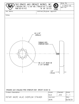
Framing and Support
The drain/overfl ow of the bath extends below the bottom of the bath. Note that this requires a cutout in the fl oor.
The fl oor structure beneath the bath must be able to support a total weight of bath, water, and bather. Refer to the
table under total weight for your model. The unit must be supported from the bottom of the bath and not from the bath rim
or nailing fl ange. If the subfl oor is level and a continuous surface, no other preparation is necessary. You can proceed to install
the bath. If the subfl oor is not level, you MUST level the entire surface prior to installing the bath. The use of materials that shim
or provide a level installation are allowed provided the method used will insure a level bath that is supported from the bottom.
Materials that may be used are a fl oor leveling compound, mortar, plaster or minimal expansion structural foam; however the
bath must remain level in order for it to drain properly and all foam feet must make full contact with the leveling material. Both
sides of a joint or splice of subfl oor should be level to each other.
NOTE: Drop-In Bath units are equipped with metal anchor straps. These straps can be used to secure the unit to the
fl oor or sub-fl oor to reduce movement after installation. If mortar or similar anchoring material is used, these straps
are not necessary.
WARNING: ALL foam feet must contact the fl oor. Anchoring straps and/or other anchoring materials will not properly
anchor unit if ALL foam feet are NOT in contact with a level fl oor. Operating a unit improperly installed may cause ir-
reparable damage to the unit.
The rim of the bath is not designed to support weight. If fi nish material is to overlap or contact the bath, the added weight
must be fully self-supporting.
Install optional trim parts when all installation has been completed.
The protective fi lm liner inside the bath is used to help prevent damage to the fi nish during installation. Before instal-
lation, remove liner to inspect for any defects, reapply and do not remove until fi nal cleanup.
FLUSH TO WALL
SEMI-SUNKEN
TILE
1" X 4" (NOT FOR SUPPORT)
MORTAR OR ADHESIVE
FLASHING
SEALANT
SUB-FLOOR
FLASHING
SEALANT
MORTAR OR ADHESIVE
TILE
TYPICAL INSTALLATIONS
1" X 4" (NOT FOR SUPPORT)
INSTALLATION
NAIL OR SCREW
THROUGH
ANCHOR STRAP
INTO FLOOR
FLOOR
ANCHOR
STRAP
Service Access
For partially or fully sunken installations, allow for access to
service connections. It is the installer's responsibility to pro-
vide suffi cient service access. The recommended minimum
dimensions allowable for service to the bath are shown in the
"Service Access" illustration below.
Provide adequate ventilation for cooling and to supply suf-
fi cient air for the blower. Also provide adequate area around
unit for air circulation for cooling the motor and to supply suf-
fi cient air to the jets.
Do not insulate this area or around blower or motor.
PUMP/MOTOR
24"
PUMP/MOTOR & BLOWER SERVICE ACCESS - REQUIRED
12"
BLOWER
FRONT
HEATER

ENGLISH
14
Jacuzzi Whirlpool Bath EL21000B 10/06
ELECTRICAL CONNECTION - BLOWER
DUPLEX
RECEPT. *
3 PRONG
PLUG
*(NOT PROVIDED)
FLOOR
4" MIN.
OR IN
ACCORDANCE
WITH LOCAL
& BUILDING OR
ELECTRICAL
CODES
Two (2) separate Ground Fault Circuit Interrupter (GFCI)
are required for the Salon™ Spa units (except Mito™ 6).
The Mito™ 6 requires a single Ground Fault Circuit Interrupter
(GFCI). Electrical connections should be performed by a
licensed electrician.
A separate 240 VAC, 20 AMP, GFCI electrical circuit is
required for the heater and pump/motor for all units except
the Mito™ 6. The Mito™ 6 requires a separate 120 VAC, 20
AMP, GFCI electrical circuit.
A separate 120 VAC, 20 AMP, GFCI electrical circuit is
required for the blower (except Mito™ 6).
DANGER: RISK OF ELECTRIC SHOCK. Connect only to a
circuit protected by a Ground Fault Circuit Interrupter.
DANGER: RISK OF COMPONENT OVERHEAT. Do NOT use
electric extension cord to provide power to unit.
CAUTION: Operating the motor/pump without enough
water in the bath can cause leaking and permanent dam-
age to the pump.
NOTE: At initial start up the 8 button electronic control
system enters an automatic self diagnostic program for
15-20 seconds. During the diagnostic program the system
will not accept user commands.
ELECTRICAL CONNECTION - HEATER AND PUMP/MOTOR
T
M
240V GFCI
PROTECTED
CIRCUIT*
HEATER
SUPPLIED POWER CORD
FROM JUNCTION BOX TO
GFCI PROTECTED
CIRCUIT
4" MIN.
OR IN
ACCORDANCE
WITH LOCAL
BUILDING OR
ELECTRICAL
CODES
*(NOT PROVIDED)
Electrical Connections
BLOWER (Except Mito™ 6)
Install a 120 VAC, 20 AMP, GFCI duplex outlet to the stud-
wall underneath the bathtub, at least 4 inches (10,2 cm) above
the fl oor. The duplex outlet is not provided. .
PUMP/MOTOR AND HEATER (Except Mito™ 6)
Install a 240 VAC, 20 AMP RATED GFCI single outlet to the
studwall underneath the bathtub, at least 4 inches (10,2 cm)
above the fl oor. The single outlet is not provided.
Power cords from the heater and the pump/motor are routed
to a fused junction box at the factory. A supplied power cord
from the junction box with a 240 VAC plug connects to the
customer supplied GFCI dedicated circuit.
With a #8 solid copper wire, bond the heater to the house
electrical panel or approved local bond. A bonding lug is
provided on the heater.
At initial start-up and before each use thereafter with power
ON, push the GFCI test button. The reset button should pop
out. Push this button in to reset. If the interrupter fails to
operate in this manner, there is a ground current fl owing or a
device malfunction, indicating the possibility of electrical shock.
Turn OFF power and do not use the bath until the source
of the problem has been identifi ed and corrected.
BLOWER
BLOWER
POWER CORD
TO WATER
SENSORS
TO CONTROL
PANEL
DANGER: RISK OF ELECTRIC SHOCK. Before servicing
these connections disconnect all power supply to both
120 VAC service and 240 VAC service.
JUNCTION
BOX
PLUG INTO
240V 20AMP GFCI RECEPTACLE
FEMALE PLUG
240VAC, 12AMP
(FOR CONTROL BOX)
FEMALE PLUG
240VAC, 15AMP
(FOR HEATER)
FUSES
(DO NOT REMOVE)
FUSES
(DO NOT REMOVE)
JUNCTION BOX CONNECTIONS
DANGER: RISK OF ELECTRIC SHOCK. Before servicing
these connections disconnect all power supply to both
120 VAC service and 240 VAC service.
SALON™ SPA CONTROL BOX CONNECTIONS
TO CONTROL PANEL
TO LED LIGHT(S)
TO MOTOR
(4 PIN CONNECTOR)
TO JUNCTION BOX
(MALE CONNECTOR)
TO WATER LEVEL
SENSOR
TO AIR FLOW VALVES
INSTALLATION

ENGLISH
15
Jacuzzi Whirlpool Bath EL21000B 10/06
INSTALLATION
FUZION™ Control Panel Installation
NOTE: The Fuzion™ control panel is delivered loose and
must be installed during the tub install.
For Fuzion™ drop-in and undermount installations, install
the control panel as shown below.
The control panel cutout opening in the assembled wood
frame and tub and in the assembled counter and tub must be
clear and free of adhesive.
Control panel and wire to be free of defects. Insert wire
into panel connector.
Apply adhesive sparingly around base of control panel.
Thread wire through cutout and to control box. Orientate
control panel so that the Jacuzzi logo is read from the inside
of the tub. Lower control panel in cutout and press fi rmly to
embed adhesive.
Connect wire to control box.
Adhesive
Apply sparingly to
avoid squeeze out
Connect Blower
wire here
(Grey wire)
Connect Control Box
wire here
(Black wire)
Inside of tub
Inside of tub
ELECTRICAL CONNECTION
115 VAC
DUPLEX
RECEPT GFCI
(NOT PROVIDED)
115 VAC
3 PRONG
PLUG FROM
JUNCTION BOX
FLOOR
4" MIN.
OR IN
ACCORDANCE
WITH LOCAL
BUILDING OR
ELECTRICAL
CODES
HEATER BLANK
PUMP/MOTOR AND BLOWER FOR MITO™ 6
The Mito™ 6 unit comes with a blower, a pump/motor, and a heater blank. The Inline Heater must be purchased separately.
Follow the installation instructions provided with the Inline Heater if an Inline Heater has been purchased separately and is to be
installed at this time. The blower and pump motor are connected to a 120 VAC junction box.
Install a 120 VAC, 20 AMP RATED GFCI single outlet to the studwall underneath the bathtub, at least 4 inches (10,2 cm)
above the fl oor. The single outlet is not provided. A supplied power cord from the junction box with a 120 VAC plug connects to
the customer supplied GFCI dedicated circuit.
At initial start-up and before each use thereafter with power ON, push the GFCI test button. The reset button should pop
out. Push this button in to reset. If the interrupter fails to operate in this manner, there is a ground current fl owing or a device
malfunction, indicating the possibility of electrical shock. Turn OFF power and do not use the bath until the source of the
problem has been identifi ed and corrected.
JUNCTION
BOX
PLUG INTO
120V 20AMP GFCI RECEPTACLE
FEMALE PLUG
120VAC, 7AMP
(FOR CONTROL BOX &
PUMP/MOTOR)
FEMALE PLUG
120VAC, 12AMP
(FOR BLOWER)
FUSE
(DO NOT REMOVE)
FUSE
(DO NOT REMOVE)
JUNCTION BOX CONNECTIONS
DANGER: RISK OF ELECTRIC SHOCK. Before servicing
these connections disconnect all power supply to 120
VAC service.
Electrical Connections (continued)

ENGLISH
16
Jacuzzi Whirlpool Bath EL21000B 10/06
Drain Information
A drain/overfl ow assembly (sold separately) must be installed
on the bath, water tested, and connected to the sanitary system
of the house. After opening the carton, inspect for damage and
verify that the kit is of the proper fi nish. In the Jacuzzi Whirlpool
Bath drain/overfl ow kit (supplied with some models), note that
the waste fl ange, strainer, overfl ow cover and cover screws
are packaged in a separate package within the kit to protect
the trim fi nish. Follow the installation instructions provided
with the drain/overfl ow kit. After the drain is fully installed,
test for proper drainage. If the unit does not drain properly,
rectify this condition before proceeding with the installation.
Jacuzzi Whirlpool Bath is not responsible for removal and or
reinstallation costs.
NOTE: Watertight installation of the drain is the installer’s
responsibility. Drain leakage is excluded from the Jacuzzi
Whirlpool Bath warranty of this product.
NOTE: FUZION™ TUBS ONLY - The supplied overfl ow
fi tting of the drain/overfl ow assembly MUST be installed
before the wood frame or (for undermount tubs) the
counter is installed.
Plumbing and Water Supply
Plumbing
Pump, jets, and suction fi ttings for the whirlpool system are
factory plumbed in schedule 40 PVC piping.
All Jacuzzi Whirlpool Salon™ Spa Bath products are factory
tested for proper operation and watertight connections prior to
shipping. If leaks are detected, notify your Jacuzzi Whirlpool
Bath Dealer. Do not install the unit.
Water Supply
Consult local authorities for plumbing code requirements
in your area.
IMPORTANT: Proper installation of the fi ll spout plumbing
and compliance with local codes are the responsibility
of the installer. Jacuzzi Whirlpool Bath does not war-
rant connections of water supply fi ttings and piping, fi ll
systems, or drain/overfl ow systems. Nor is it responsible
for damage to the bath which occurs during installation.
CAUTION: A nonfl ammable protective barrier must be
placed between soldering work and bath unit to prevent
damage to the bath.
*ANTI-SIPHON VALVE
BATH RIM
6"
* NOT
PROVIDED
Anti-Siphon Valve (Optional)
Optional Anti-Siphon valve installation. The Anti-Siphon
valve is not supplied with the tub. Consult your local plumb-
ing code requirements for the minimum height above the tub
rim.
Fuzion™ Overfl ow Fitting Installation
The supplied overfl ow fi tting of the drain/overfl ow assembly
MUST be installed before the wood frame or (for undermount
tubs) the counter is installed.
Remove and open the overfl ow fi tting from the drain kit (sup-
plied). Remove washers and nuts from the overfl ow fi tting.
Place a small bead of plumbers putty, silicone, or similar
approved sealant around the underside of the top fl ange. Place
the overfl ow fi tting into the overfl ow hole of the tub.
From the underside of the unit, place the rubber washer
then locknut on the fi tting and tighten securely. Be careful
not to over tighten.
The 1-1/2" (38 mm) overfl ow fi tting connects with standard
drain plumbing fi ttings widely available at local hardware and
plumbing stores. Assemble in accordance with local plumbing
or building codes.
After the drain is fully installed, test for proper drainage. If
the unit does not drain properly, rectify this condition before
proceeding with the installation. Jacuzzi Whirlpool Bath is not
responsible for removal and or reinstallation costs.
NOTE: Watertight installation of the drain is the installer’s
responsibility. Drain leakage is excluded from the Jacuzzi
Whirlpool Bath warranty of this product.
Clean-Up After Installation
To avoid dulling and scratching the surface of the bath,
never use abrasive cleaners. A mild liquid detergent and warm
water will clean soiled surfaces.
Remove spilled plaster with a wood or plastic edge. Metal
tools will scratch the surface. Spots left by plaster or grout
can be removed if lightly rubbed with detergent on a damp
cloth or sponge.
Paint, tar, or other diffi cult surface stains can be removed
with paint thinner, turpentine, or isopropyl alcohol (rubbing
alcohol). NOTE: Use these chemicals only on SURFACE
stains.
Minor scratches which do not penetrate the color fi nish can
be removed by lightly sanding with 600-grit wet/dry sandpaper.
You can restore the glossy fi nish to the acrylic surface of the
bath with a special compound, Meguiar's #10 Mirror Glaze.
If that is not available, use automotive rubbing compound fol-
lowed by an application of automotive paste wax.
Major scratches and gouges which penetrate the acrylic
surface will require refi nishing. Ask your Jacuzzi Whirlpool
Bath dealer for special instructions or visit our web site at
http://www.jacuzzi.com/ to fi nd a service agent listing for Sur-
face or Shell-Related Problems.
O
VERFL
O
W
FITTING
APPLY
PUTTY/SEALANT
(NOT PROVIDED)
FLAT RUBBER WASHER
LOCKNUT
TIGHT
WASTE ELBOW
(NOT PROVIDED)

ENGLISH
17
Jacuzzi Whirlpool Bath EL21000B 10/06
TYPICAL BATH FITTINGS
Operation
NOTE: These instructions pertain to all bath products manufactured by Jacuzzi Whirlpool Bath. Not all features dis-
cussed in this instruction pamphlet apply to all baths.
All baths manufactured by Jacuzzi Whirlpool Bath are designed for "fi ll and drain," which means the bath should be drained
after each use and fi lled with fresh water by the next bather. This is a health precaution, as these baths are not designed to hold
water continuously like pools or spas. If you want a unit designed to continuously hold water, see your Jacuzzi Whirlpool Bath
dealer for the complete line of spas available.
Once the bath is installed, remove any residue or foreign materials left over from construction. Paint, tar, or other diffi cult surface
stains can be removed with paint thinner, turpentine, or isopropyl alcohol (rubbing alcohol). NOTE: Use these chemicals only on
SURFACE stains. Other dirt can be cleaned off with a mild liquid detergent on a damp cloth. Scrape off plaster with a wooden
or plastic edge; do not use metal scrapers, wire brushes or other metal tools, as they will damage the bath's surface.
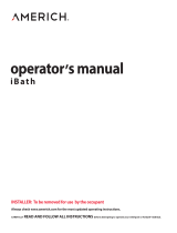
Water Level
Close the drain and fi ll the bath until water is at least 1" to 2" (25,4 to 50,8 mm) above the highest jet (see water line indicated
in the illustration). Do not turn on the whirlpool system at any time if the jets are not completely immersed in water.
Running the whirlpool system when there is insuffi cient water in the bath could result in water spraying outside the bath area.
Running the whirlpool system without water will damage the recirculating pump.
IMPORTANT: When exiting the bath, the water level will drop below the jets which could result in water being sprayed out of the
unit. To prevent this, you must turn unit OFF before exiting bath.
OPERATING INSTRUCTIONS
1" - 2"
FILL TO AT LEAST
1" - 2" ABOVE HIGHEST JET
DRAIN/OVERFLOW
T
YPICAL SALON™ SPA FITTINGS
SALON
CONTROL PANEL
AIR JETS
FULLY
ADJUSTABLE
SIDE JETS
FULLY
ADJUSTABLE
BACK JETS
WATER LEVEL
SENSORS
SUCTION COVER

ENGLISH
18
Jacuzzi Whirlpool Bath EL21000B 10/06
Electronic Control Panel Operation (with standard Chromatherapy lighting)
All tubs in this product line (except the Mito™ 6) come with electronic controls and standard Chromatherapy lighting. Read
and follow the operation instructions for the control system of your unit.
General Functions
This Jacuzzi tub is equipped with a eight button electronic control panel. The eight button panel controls a two speed pump/
motor, Chromatherapy lighting, air controls, blower, and wave control. LED lights (on the control panel) indicate function levels.
When switching between functions, the LED for the inactive functions will dim and the active function will brighten.
The bath is equipped with two water level sensors. When the water level is below the sensors, the pump/motor can not be
activated. If the ON/OFF pump/motor button is pressed at this time, the pump/motor will not operate. When the water goes
above the water level sensor, the pump/motor can be activated. If the water level drops below the level sensor, the pump/motor
will shut OFF. To restart the pump/motor after the water level goes above the level sensor, the ON/OFF pump/motor button must
be pressed. The pump/motor will automatically shut off 30 minutes after the pump/motor was turned on.
When the water level is below the sensors, the blower cannot be activated using the control panel. The blower will activate
a Drain cycle and a Purge Cycle when two conditions are met: the water level is below the sensors and the controls have been
shut down. See Drain Cycle - Air Bath on page 21 for an explanation of these cycles.
NOTE: Ensure the water level sensors located inside the bath are free of any soap or dirt buildup.
CONTROL PANEL OPERATION (WHIRLPOOL AND AIR BATH) [EXCEPT MITO™ 6]

ENGLISH
19
Jacuzzi Whirlpool Bath EL21000B 10/06
Normal Operation (with the bath fi lled to the proper level)
Bath Light
Right Air Valve
Left Air Valve
Left Air Valve
Status LEDs
Right Air Valve
Status LEDs
Pump/Motor
Status LEDs
ON/OFF
Pump/Motor
Wave
Function
Toggle
Switches
Air Bath
Blower Status
LEDs
Wave Function Switch (ON/OFF )
Pressing this
button activates wave action by opening
and closing air valves. Pressing a second time will turn OFF
the wave action.
• When pressing this button after pressing the Pump/Mo-
tor button or the Air Valve button the wave action will
work on both Right and Left Air valves.
Air Bath Switch
Pressing this
button will activate the blower using the
Toggle buttons to increase/decrease air fl ow from the blower.
Blower air can be adjusted from low air to maximum air.
Air Bath Status LED
The Air Bath Status LED will show four LED lights at maxi-
mum air and only one LED light when the air is turned OFF.
Each additional LED indicates more air fl ow.
Toggle Switches
The Toggle buttons, up
and down , act on each
of the other switches to increase, decrease, or modify func-
tionality. Use the up arrow to increase and the down arrow
to decrease.
• Pressing a toggle button after pressing the Pump/Motor
button will increase or decrease speeds on the Pump/Mo-
tor. If the pump/motor is on HIGH speed press the down
arrow to select LOW speed. If the pump/motor is on LOW
speed press the up arrow to select HIGH speed.
• Pressing an up or down toggle button after pressing the
Bath Light button once will increase or decrease the white
light brightness. Pressing an up or down toggle button after
pressing the Bath Light button twice will begin cycling the
light colors. Leave the colors cycling or press the same
toggle button again to stop the color cycling. With the lights
stopped on a color pressing the Bath Light button a third
time will turn OFF the light. (A favorite color will be saved
ONLY when the cycling has been stopped on that color
and then turned OFF.)
• Pressing a toggle button after pressing both the Pump/
Motor button fi rst and then the Wave Function button
will increase or decrease wave action on both air valves.
Pressing a toggle button after pressing either Air Valve but-
tons increase or decrease wave action on that air valve.
• Pressing a toggle button after pressing the Air Bath Switch
increase or decrease the air fl ow through the bottom air
channels.
Pump/Motor Switch (ON/OFF )
Pressing the
button will turn ON the two speed pump/
motor at HIGH speed. Pressing a second time will turn OFF
the pump/motor. To change speeds use the Toggle buttons.
Pump/Motor Status LED
When the pump/motor is ON at HIGH speed all four LED
indicator lights will be lit. When the pump/motor is ON at LOW
speed the bottom LED indicator light will be lit.
Left Air Valve Switch
Pressing this
button will activate the left air valves
using the Toggle buttons to increase/decrease air fl ow to the
left set of jets. The air fl ow can be adjusted from no air to
maximum air.
Left Air Valve Status LED
The Left Air Valve Status LED will show four LED lights at
maximum air and only one LED light when the air is turned
OFF. Each additional LED indicates more air fl ow.
Right Air Valve Switch
Pressing this
button will activate the right air valves.
Use the Toggle buttons to increase/decrease air fl ow to the
right set of jets. The air fl ow can be adjusted from no air to
maximum air.
Right Air Valve Status LED
The Right Air Valve Status LED will show four LED lights
at maximum air and only one LED light when the air is turned
OFF. Each additional LED indicates more air fl ow.
Bath Light Switch (ON/OFF )
Pressing this
button will turn ON the white bath light(s).
Pressing the Toggle buttons at this time will increase or de-
crease light intensity. Pressing the
button a second time
will access the saved favorite color. To cycle lighting colors
use the Toggle button. Pressing the Toggle button again will
stop the light cycling. The color displayed when the cycle has
been stopped will be saved as your favorite color. Pressing
the
button a third time to turn OFF the light.
NOTE: When switching between functions, the LED for the in-
active functions will dim and the active function will brighten.

ENGLISH
Control Panel Operation, Mito™ 6 Air Bath Controls
General Functions
Normal Mode: Press this button to turn the blower ON. The blower will be on for 20 minutes. The intensity may be changed
by using either the up arrow button or the down arrow button. Pressing this button a second time will turn the blower OFF. When
the blower is turned off the blower will continue to run for 10 seconds to allow the heater element to cool.
Wave Mode: Press this button to change the blower's power from a minimum to a user defi ned maximum. Press this button
a second time to return to normal mode where the blower's power is constant.
In the Normal mode with the blower power constant, press the UP arrow to increase or the DOWN arrow to decrease. In
Wave mode these buttons change the blower's power to a user defi ned maximum.
Control Panel Operation, Mito™ 6 Whirlpool Controls
General Functions
The Electronic Control ON/OFF Switch, conveniently located on the bath, allows you to turn the whirlpool system on and
off while in the bath. Simply push down on the switch button to turn on the whirlpool system. To turn the system OFF, push
down on the button again.
The control switch will automatically shut OFF after 20 minutes. Push down on the switch button to restart the whirlpool system
again.
20
Jacuzzi Whirlpool Bath EL21000B 10/06
CONTROL PANEL OPERATION (WHIRLPOOL AND AIR BATH FOR MITO™ 6]
The Mito™ 6 has two control panels, one Air Bath and one Whirlpool.
/