Page is loading ...

Frequency Inverter
Convertidor de Frecuencia
Inversor de Frequência
CFW500
Motors | Automation | Energy | Transmission & Distribution | Coatings
User’s Manual
Manual del Usuario
Manual do Usuário
Language: English, Spanish, Portuguese

User’s Manual
Series: CFW500
Language: English
Document: 10001278006 / 08
Models: Frame Sizes A ... F
Date: 08/2019

Summary of Reviews
English
The information below describes the reviews made in this manual.
Version Review Description
- R00 First edition
- R01 General review and inclusion of the new models
- R02 Modification in Table B.6 on page 165 and in the printing of the filter switch
- R03 General review and inclusion of frame size D
- R04 General review
- R05 General review and inclusion of frame size C 500 / 600 V
- R06 General review and inclusion of frame size E
- R07 General review
- R08 General review, inclusion of frame size F and functional safety
NOTE!
The inverters CFW500 have the default parameters set as described below:
60 Hz for models without internal filter.
50 HZ for models with internal filter (check the smart code
E.g.: CFW500A04P3S2NB20C2).
ATTENTION!
Check the frequency of the power supply.
In case the power supply frequency is different from the default frequency
(check P0403), it is necessary to set:
P0204 = 5 for 60 Hz.
P0204 = 6 for 50 Hz.
It is only necessary to set these parameters once.
Refer to the programming manual of the CFW500 for further details about the
setting of parameter P0204.

Contents
English
1 SAFETY INSTRUCTIONS ..................................................................1
1.1 SAFETY WARNINGS IN THIS MANUAL ................................................ 1
1.2 SAFETY WARNINGS IN THE PRODUCT .............................................. 1
1.3 PRELIMINARY RECOMMENDATIONS ................................................. 2
2 GENERAL INFORMATION ................................................................4
2.1 ABOUT THE MANUAL ........................................................................... 4
2.2 ABOUT THE CFW500 ............................................................................. 4
2.3 NOMENCLATURE .................................................................................. 8
2.4 IDENTIFICATION LABELS ................................................................... 10
2.5 RECEIVING AND STORAGE ................................................................ 11
3 INSTALLATION AND CONNECTION ..............................................13
3.1 MECHANICAL INSTALLATION ............................................................ 13
3.1.1 Environmental Conditions ......................................................... 13
3.1.2 Positioning and Mounting.......................................................... 13
3.1.2.1 Cabinet Mounting ........................................................... 14
3.1.2.2 Surface Mounting ........................................................... 14
3.1.2.3 DIN-Rail Mounting .......................................................... 14
3.1.2.4 Flange mounting ............................................................ 14
3.2 ELECTRICAL INSTALLATION ............................................................. 15
3.2.1 Identification of the Power Terminals and Grounding
Points .................................................................................................... 15
3.2.2 Power and Grounding Wiring, Circuit Breakers and Fuses .... 16
3.2.3 Power Connections .................................................................... 17
3.2.3.1 Input Connections .......................................................... 18
3.2.3.2 Inductor of the DC Link/ Reactance of the Power
Supply .......................................................................................... 18
3.2.3.3 IT Networks..................................................................... 19
3.2.3.4 Dynamic Braking ............................................................ 19
3.2.3.5 Output Connections ...................................................... 21
3.2.4 Grounding Connections ............................................................ 22
3.2.5 Control Connections ................................................................. 23
3.2.6 Cable Separation Distance ....................................................... 25
3.3 INSTALLATIONS ACCORDING TO EUROPEAN DIRECTIVE OF
ELECTROMAGNETIC COMPATIBILITY .................................................. 25
3.3.1 Conformal Installation .............................................................. 25
3.3.2 Emission and Immunity Levels ................................................. 26
4 HMI (KEYPAD) AND BASIC PROGRAMMING .............................27
4.1 USE OF THE HMI TO OPERATE THE INVERTER .............................. 27
4.2 INDICATIONS ON THE HMI DISPLAY ................................................ 28
4.3 OPERATING MODES OF THE HMI .................................................... 29

Contents
English
5 POWERING UP AND STARTUP......................................................31
5.1 PREPARATION AND POWERING UP .................................................. 31
5.2 STARTUP .............................................................................................. 32
5.2.1 STARTUP Menu .......................................................................... 32
5.2.1.1 V/f Control Type (P0202 = 0) ......................................... 32
5.2.1.2 VVW Control Type (P0202 = 5) ................................... 33
5.2.2 Menu BASIC - Basic Application .............................................. 36
6 TROUBLESHOOTING AND MAINTENANCE .................................37
6.1 FAULT AND ALARMS ........................................................................... 37
6.2 SOLUTIONS FOR THE MOST FREQUENT PROBLEMS ................... 37
6.3 DATA TO CONTACT THE TECHNICAL ASSISTANCE ....................... 38
6.4 PREVENTIVE MAINTENANCE............................................................. 38
6.5 CLEANING INSTRUCTIONS ............................................................... 39
7 OPTIONAL KITS AND ACCESSORIES .........................................41
7.1 OPTIONAL KITS ................................................................................... 41
7.1.1 RFI Filter ....................................................................................... 41
7.1.2 Protection Rate Nema1 ............................................................. 41
7.1.3 Safety Functions ......................................................................... 41
7.2 ACCESSORIES ...................................................................................... 41
8 TECHNICAL SPECIFICATIONS .................................................... 44
8.1 POWER DATA ....................................................................................... 44
8.2 ELECTRONICS/GENERAL DATA ........................................................ 44
8.2.1 Codes and Standards ................................................................ 46
8.3 CERTIFICATIONS ................................................................................. 46

CFW500 | 1
Safety Instructions
English
1 SAFETY INSTRUCTIONS
This manual contains the information necessary for the correct use of the frequency inverter
CFW500.
It was developed to be operated by people with proper technical training or qualification to
handle this kind of equipment. Those people must follow the safety instructions defined by
local standards. The non compliance with the safety instructions may result in death risks and/
or damages to the equipment.
1.1 SAFETY WARNINGS IN THIS MANUAL
DANGER!
The procedures recommended in this warning aim at protecting the user against
death, serious injuries and considerable material damages.
DANGER!
Les procédures concernées par cet avertissement sont destinées à protéger
l'utilisateur contre des dangers mortels, des blessures et des détériorations
matérielles importantes.
ATTENTION!
The procedures recommended in this warning aim at preventing material
damages.
NOTE!
The information mentioned in this warning is important for the proper
understanding and good operation of the product.
1.2 SAFETY WARNINGS IN THE PRODUCT
High voltages present.
Components sensitive to electrostatic discharges. Do not touch them.
The connection to the protection grounding is required (PE).
Connection of the shield to the grounding.

2 | CFW500
Safety Instructions
English
1.3 PRELIMINARY RECOMMENDATIONS
DANGER!
Always disconnect the general power supply before changing any electric
component associated to the inverter. Many components may remain loaded
with high voltages and/or moving (fans), even after the AC power supply input
is disconnected or turned off. Wait for at least ten minutes in order to guarantee
the full discharge of the capacitors. Always connect the grounding point of the
inverter to the protection grounding.
DANGER!
Débranchez toujours l'alimentation principale avant d'entrer en contact avec un
appareil électrique associé au variateur. Plusieurs composants peuvent rester
chargés à un potentiel électrique élevé et/ou être en mouvement (ventilateurs),
même après la déconnexion ou la coupure de l'alimentation en courant
alternatif. Attendez au moins 10 minutes que les condensateurs se déchargent
complètement. Toujours connecter le point de mise à la terre du variateur sur
la mise à la terre de protection.
NOTES!
Frequency inverters may interfere in other electronic equipment. Observe
the recommendations of Chapter 3 INSTALLATION AND CONNECTION on
page 13 in order to minimize these effects.
Read the entire manual before installing or operating this inverter.
Do not execute any applied potential test (hi-pot test) on the inverter!
If necessary, contact WEG.
ATTENTION!
The electronic cards have components sensitive to electrostatic discharges.
Do not touch the components or connectors directly. If necessary, first touch
the grounding point of the inverter which must be connected to the protection
ground or use a proper grounding strap.
DANGER!
Crushing Hazard
In order to ensure safety in load lifting applications, electric and/or mechanical
devices must be installed outside the inverter for protection against accidental
fall of load.

CFW500 | 3
General Information
English
DANGER!
This product was not designed to be used as a safety element. Additional
measures must be taken so as to avoid material and personal damages.
The product was manufactured under strict quality control, however, if installed
in systems where its failure causes risks of material or personal damages,
additional external safety devices must ensure a safety condition in case of a
product failure, preventing accidents.
DANGER!
Risque d'écrasement
Afin d'assurer la sécurité dans les applications de levage de charges, les
équipements électriques et/ou mécaniques doivent être installés hors du
variateur pour éviter une chute accidentelle des charges.
DANGER!
Ce produit n'est pas conçu pour être utilisé comme un élément de sécurité. Des
précautions supplémentaires doivent être prises afin d'éviter des dommages
matériels ou corporels.
Ce produit a été fabriqué sous un contrôle de qualité conséquent, mais s'il est
installé sur des systèmes où son dysfonctionnement entraîne des risques de
dommages matériels ou corporels, alors des dispositifs de sécurité externes
supplémentaires doivent assurer des conditions de sécurité en cas de
défaillance du produit, afin d'éviter des accidents.
ATTENTION!
When in operation, electric energy systems – such as transformers, converters,
motors and cables – generate electromagnetic fields (EMF), posing a risk to
people with pacemakers or implants who stay in close proximity to them.
Therefore, those people must stay at least 2 meters away from such equipment.

4 | CFW500
General Information
English
2 GENERAL INFORMATION
2.1 ABOUT THE MANUAL
This manual contains information for the proper installation and operation of the inverter, as well
as start-up procedures, main technical features and how to identify the most usual problems
of the different models of inverters of the line CFW500.
ATTENTION!
The operation of this equipment requires detailed installation and operation
instructions provided in the user’s manual, programming manual and
communication manuals. These file are available on the WEG’s website -
www.weg.net. A printed copy of the files can be requested at your local
WEG dealer.
NOTE!
It is not the intention of this manual to present all the possibilities for the
application of the CFW500, as well as WEG cannot take any liability for the use
of the CFW500 which is not based on this manual.
Part of the figures and tables are available in the appendixes, which are divided into APPENDIX
A - FIGURES on page 151 and APPENDIX B - TECHNICAL SPECIFICATIONS on page 157.
The information is presented in three languages.
2.2 ABOUT THE CFW500
The frequency inverter CFW500 is a high-performance product which allows the speed and
torque control of three-phase induction motors. This product offers up to four options to control
the motor: V/f scalar control, VVW control, vector control with sensor and sensorless.
In the vector control, the operation is optimized for the used motor, providing a better performance
in terms of speed and torque control. The "Self-Tuning" function, available for the vector control,
allows the automatic setting of control parameters and controllers based on the identification
of the motor parameters.
The VVW control (Voltage Vector WEG) has a performance and precision between the V/f scalar
control and the vector control; on the other hand, it adds robustness and simplicity to drive
motors without speed sensors. The self-tuning function is also available in the VVW control.
The scalar control (V/f) is recommended for simpler applications, such as the activation of most
pumps and fans. The V/f mode is used when more than a motor is activated by an inverter
simultaneously (multimotor applications).
The frequency inverter CFW500 also has functions of PLC (Programmable Logic Controller)
by means of the SoftPLC (integrated) feature. For further details regarding the programming of
those functions, refer to the SoftPLC user's manual of the CFW500.
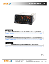
The main components of the CFW500 can be viewed in the block diagram Figure 2.1 on
page 5 for frame sizes A, B, and C, Figure 2.2 on page 6 for frame sizes D and E and
Figure 2.3 on page 7 for frame size F.

CFW500 | 5
General Information
English
Analog input
(AI1)
(*)
Digital inputs
(DI1 to DI4)
(*)
Supplies for electronics and interfaces
between power and control
RS485
PC
Power
Single-phase /
three-phase
rectifier
Internal
RFI filter
(available in
the inverters
CFW500...C...)
Motor
U/T1
V/T2
W/T3
+UD
-UD
BR
Inverter with
insulated gate bipolar
transistors and
current feedback
Power
supply
R/L1/L
S/L2/N
T/L3
= connection for DC link
(**)
= connection for brake resistor
(**)
Preload
Software WLP
SUPERDRIVE
(*)
MODBUS
Capacitor bank DC Link
Braking IGBT (available in the inverters
CFW500...DB...)
HMI
CPU
32 bits
"RISC"
EEPROM
(memory)
User’s
Plug-in
card
Interfaces
(RS232,
RS485
or USB)
Analog output
(AO1)
(*)
Power supply 24 V
Power supply 10 V
Digital output
DO1 (RL1)
Digital output
DO2 (TR)
(*)
HMI (remote)
Feedback
(**)
:
- voltage
- current
PE
PE
Memory card (MCard)
Accessory
Control
Control
Standard plug-in
= Human-machine interface
(*) The number of analog/digital inputs/outputs, as well as other resources, may vary according to the plug-in module used.
For further information, refer to the guide supplied with the accessory.
(**) Not available in frame size A.
Figure 2.1: Block diagram of CFW500 for frame sizes A, B and C

6 | CFW500
General Information
English
Analog input
(AI1)
(*)
Digital inputs
(DI1 to DI4)
(*)
Supplies for electronics and interfaces
between power and control
RS485
PC
Power
Single-phase /
three-phase
rectifier
Brake resistor (optional)
Inductor of the DC link (optional)
Internal
RFI filter
(available in
the inverters
CFW500...C...)
Motor
U/T1
V/T2
W/T3
+UD
-UD
BR
Inverter with
IGBT transistors
Power
supply
R/L1/L
S/L2/N
T/L3
= connection for DC link
= connection for brake resistor
Preload
Software WLP
SUPERDRIVE
(*)
MODBUS
Capacitor bank DC Link
Braking IGBT (available in the inverters
CFW500...DB...)
HMI
CPU
32 bits
"RISC"
EEPROM
(memory)
User’s
plug-in
card
Interfaces
(RS232,
RS485
or USB)
Analog output
(AO1)
(*)
Power supply 24 V
Power supply 10 V
Digital output
DO1 (RL1)
Digital output
DO2 (TR)
(*)
HMI (remote)
Feedback:
- voltage
- current
PE
PE
Memory card (MCard)
Accessory
Control
Control
Standard plug-in
= Human-machine interface
(*) The number of analog/digital inputs/outputs, as well as other resources, may vary according to the plug-in module used. For further information,
refer to the guide supplied with the accessory.
Figure 2.2: Block diagram of CFW500 for frame sizes D and E

CFW500 | 7
General Information
English
Analog input
(AI1)
(*)
Digital inputs
(DI1 to DI4)
(*)
Supplies for electronics and interfaces between
power and control
RS485
Power
Brake resistor (optional)
Motor
U/T1
V/T2
W/T3
Inverter
with IGBT
transistors
Power
supply
R/L1/L
S/L2/N
T/L3
Capacitor bank DC Link
Braking IGBT (available in the
inverters CFW500...DB...)
HMI
CPU
32 bits
"RISC"
EEPROM
(memory)
User’s
plug-in
card
Interfaces
(RS232,
RS485
or USB)
Analog output (AO1)
(*)
Power supply 24 V
Power supply 10 V
Digital output DO1 (RL1)
Digital output DO2 (TR)
(*)
HMI (remote)
Feedback:
- voltage
- current
PE
PE
Memory card (MCard)
Accessory
Control
Control
Standard plug-in
= Human-machine interface
Preload
Three-phase
rectifier
MODBUS
Software WLP
SUPERDRIVE
(*)
PC
= connection for DC link
= connection for brake resistor
+UD BR -UD
DC Link chokes
RFI filter
(*) The number of analog/digital inputs/outputs, as well as other resources, may vary according to the plug-in module used. For further information,
refer to the guide supplied with the accessory.
Figure 2.3: Block diagram of CFW500 for frame size F

8 | CFW500
General Information
English
2.3 NOMENCLATURE
Table 2.1: Nomenclature of the inverters CFW500
Product
and
Series
Identification of the Model
Brake
(*)
Protection
Rate
(*)
Conducted
Emission
Level
(*)
Safety
Functions
Hardware
Version
Special
Software
Version
Frame
Size
Rated
Current
No of
Phases
Rated
Voltage
Eg.: CFW500 A 02P6 T 4 NB 20 C2 -- --- --
Available options
CFW500
See Table 2.2 on page 9 Blank =
without
safety
functions
Blank =
standard
NB = without dynamic braking Y2 = with
safety
functions
(STO and
SS1-t, as
per IEC/EN
61800-5-2)
Sx =
special
software
DB = with dynamic braking Blank = standard
plug-in module
20 = IP20 H00 = without plug-in
N1 = cabinet Nema1 (type 1 as per UL) (protection
rate according to standard IEC IP20)
Blank = it does not meet the levels of standards
for conducted emission
C2 or C3 = as per category 2 (C2) or 3 (C3)
of IEC/EN 61800-3, with internal RFI filter
(*) The available options for each model are in Table 2.2 on page 9.
NOTE!
For models with a special software version (Sx in the smart code) and for
specific applications, refer to the application manual available for download
on www.weg.net.

CFW500 | 9
General Information
English
Table 2.2: Available options for each field of the nomenclature according to the rated current and voltage
of the inverter
Frame
Size
Output Rated
Current
(1)
N° of Phases
Rated
Voltage
Available Options for the Remaining Identification
Codes of the Inverters
Brake
Protection
Rate
Conducted
Emission Level
Hardware
Version
A
01P6 = 1.6 A
S = single-
phase power
supply
2 = 200... 240 V
NB
20 or N1
Blank or C2
Blank or
H00
02P6 = 2.6 A
04P3 = 4.3 A
07P0 = 7.0 A Blank or C3
B
07P3 = 7.3 A
DB C2
10P0 = 10 A
A
01P6 = 1.6 A
B = single-phase
or three-phase
power supply
NB
Blank
02P6 = 2.6 A
04P3 = 4.3 A
B
07P3 = 7.3 A
DB
10P0 = 10 A
A
07P0 = 7.0 A
T = three-phase
power supply
NB
09P6 = 9.6 A
B 16P0 = 16 A
DB
C 24P0 = 24 A
D
28P0 = 28 A
Blank or C3
33P0 = 33 A
47P0 = 47 A
E 56P0 = 56 A
A
01P0 = 1.0 A
4 = 380...480 V
NB
Blank or C2
01P6 = 1.6 A
02P6 = 2.6 A
04P3 = 4.3 A
06P1 = 6.1 A Blank or C3
B
02P6 = 2.6 A
DB
Blank or C204P3 = 4.3 A
06P5 = 6.5 A
10P0 = 10 A Blank or C3
C
14P0 = 14 A
Blank or C2
16P0 = 16 A
D
24P0 = 24 A
Blank or C3
31P0 = 31 A
E
39P0 = 39 A
49P0 = 49 A
F
77P0 = 77 A
88P0 = 88 A
0105 = 105 A
C
01P7 = 1.7 A
5 = 500...600 V Blank
03P0 = 3.0 A
04P3 = 4.3 A
07P0 = 7.0 A
10P0 = 10 A
12P0 = 12 A
(1) Informed currents in frame sizes A ... E are for HD operation and in frame size F, for ND operation.

10 | CFW500
General Information
English
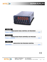
2.4 IDENTIFICATION LABELS
There are two identification labels, one complete nameplate, located on the side of the inverter
and a simplified label under the plug-in module. The label under the plug-in module allows the
identification of the most important characteristics of the inverter even in inverters mounted
side-by-side. For further details about the position of the labels, see Figure A.2 on page 153.
Manufacturing date
Production order
Rated input data
(voltage, current
and frequency)
Rated output data
(voltage, current
and frequency)
Serial number
WEG stock item
Model (Smart code
of the inverter)
a) Side label of the CFW500 - frame sizes A to E

CFW500 | 11
General Information
English
CFW500F77P0T4DB20
FREQUENCY
INVERTER
CFW500
MAT.: 14609374 SERIAL#:
OP.: 999999999
LINE
LINEA
REDE
380 - 480 VAC
3~ 64,7 A
3~ 81,6 A
50/60 Hz
Hz
FABRICADO NO BRASIL
HECHO EN BRASIL
MADE IN BRAZIL
MANUFACTURER: "WEG DRIVES & CONTROLS -
AUTOMAÇÃO LTDA"
AV. PREFEITO WALDEMAR GRUBBA, 3000
CP420, CEP 89256-900 / JARAGUÁ DO SUL - SC
7 9 0 9 4 9 2 5 2 3 2 4 6
A (HD)
A (ND)
VAC
OUTPUT
SALIDA
SAÍDA
0 - REDE
3~ 77,0 A
61,0 A
0-500 Hz
48 0
Model (Smart code
of the inverter)
WEG stock item
Serial number
Production order
Manufacturing date
Rated output data
(voltage, current and
frequency)
Rated input data
(voltage, current and
frequency)
b) Side label of the CFW500 - frame size F
Model (Smart code
of the Inverter)
Stock item
Manufacturing date
Serial number
c) Front label of the CFW500 (Under the Plug-In Module)
Figure 2.4: (a) to (c) Description of the identification labels on the CFW500
2.5 RECEIVING AND STORAGE
The CFW500 comes packaged in a cardboard box up to frame size E inverter models. The
bigger models are packed in wooden box. On this package, there is an identification label which
is the same as the one attached to the side of the inverter.
Follow the steps below to open the packaging of models larger than frame size E:
1. Put the shipping container over a flat and stable area with the assistance of another two
people.
2. Open the wood crate.
3. Remove all the packing material (the cardboard or styrofoam protection) before removing
the inverter.

12 | CFW500
General Information
English
Check if:
The identification of the CFW500 matches the model purchased.
Any damages occurred during transportation.
Report any damage immediately to the carrier.
If the CFW500 is not installed soon, store it in a clean and dry location (temperature between
-25 °C and 60 °C (-77 ºF and 140 ºF)), with a cover to prevent dust accumulation inside it.
ATTENTION!
When the inverter is stored for a long period, it becomes necessary to perform
the capacitor reforming. Refer to the procedure recommended in Section 6.4
PREVENTIVE MAINTENANCE on page 38 - of this manual.

CFW500 | 13
Installation and Connection
English
3 INSTALLATION AND CONNECTION
3.1 MECHANICAL INSTALLATION
3.1.1 Environmental Conditions
Avoid:
Direct exposure to sunlight, rain, high humidity or sea-air.
Inflammable or corrosive liquids or gases.
Excessive vibration.
Dust, metallic particles or oil mist.
Environmental conditions permitted for the operation of the inverter:
Temperature surrounding the inverter: from -10 ºC (14 ºF) to the nominal temperature specified
in Table B.4 on page 162 and Table B.5 on page 164.
Inverters for mechanics A to E: for temperatures surrounding the inverter higher than the
specifications in Table B.4 on page 162, it is necessary to apply of 2 % of current derating
for each Celsius degree, limited to an increase of 10 ºC (50 ºF).
Inverters for mechanics F: for temperatures surrounding the inverter higher than the
specifications in Table B.5 on page 164, it is necessary to apply of 1 % of current derating
for each Celsius degree, until 50 ºC (122 °F) and 2 % of current derating for each Celsius
degree, until 60 ºC (140 °F).
Air relative humidity: 5 % to 95 % non-condensing.
Maximum altitude: up to 1000 m (3.300 ft) - nominal conditions.
1000 m to 4000 m (3.300 ft to 13.200 ft) - 1 % of current derating for each 100 m (328 ft)
above 1000 m of altitude.
From 2000 m to 4000 m (6.600 ft to 13.200 ft) above sea level - maximum voltage reduction
(240 V for 200...240 V models, 480 V for 380...480 V models and 600 V for 500...600 V
models)of 1.1 % for each 100 m (330 ft) above 2000 m (6.600 ft).
Pollution degree: 2 (according to EN 50178 and UL 508C), with non-conductive pollution.
Condensation must not originate conduction through the accumulated residues.
3.1.2 Positioning and Mounting
The external dimensions and the drilling for the mounting, as well as the net weight (mass) of
the inverter are presented in Figure B.2 on page 170. For further details of each frame size,
refer to Figure B.5 on page 175, Figure B.6 on page 176, Figure B.7 on page 177, Figure
B.8 on page 178, Figure B.9 on page 179 and Figure B.10 on page 180.
Mount the inverter in the upright position on a flat and vertical surface. First, put the screws on
the surface where the inverter will be installed, install the inverter and then tighten the screws
observing the maximum torque for the screws indicated in Figure B.2 on page 170.

14 | CFW500
Installation and Connection
English
Allow the minimum clearances indicated in Figure B.3 on page 172, in order to allow the cooling
air circulation. Do not install heat sensitive components right above the inverter.
ATTENTION!
When installing two or more inverters vertically, respect the minimum
clearance A + B (as per Figure B.3 on page 172) and provide an air deflecting
plate so that the heat rising up from the bottom inverter does not affect the
top inverter.
Provide independent conduits for the physical separation of signal, control,
and power cables (refer to the Section 3.2 ELECTRICAL INSTALLATION on
page 15).
3.1.2.1 Cabinet Mounting
For inverters installed inside cabinets or metallic boxes, provide proper exhaustion, so that the
temperature remains within the allowed range. Refer to the dissipated powers in Table B.4 on
page 162 and Table B.5 on page 164.
As a reference, Table 3.1 on page 14 shows the air flow of nominal ventilation for each frame size.
Cooling Method: fan with air flow upwards.
Table 3.1: Air flow of the fan
Frame Size CFM I/s m
3
/min
A 20 9.4 0.56
B 30 14.1 0.85
C 30 14.1 0.85
D (T2)
(*)
100 47.2 2.83
D (T4)
(**)
80 37.8 2.27
E 180 84.5 5.09
F 214 100.4 6.05
(*) T2 - CFW500 frame size D line 200 V (200...240 V).
(**) T4 - CFW500 frame size D line 400 V (380...480 V).
3.1.2.2 Surface Mounting
Figure B.3 on page 172 illustrates the procedure for the installation of the CFW500 on the
mounting surface.
3.1.2.3 DIN-Rail Mounting
In frame sizes A, B and C, the inverter CFW500 can also be mounted directly on 35-mm rail as
per DIN EN 50.022. For this mounting, you must first position the lock
(*)
down and then place
the inverter on the rail, position the lock
(*)
up, fixing the inverter.
(*) The fastening lock of the inverter on the rail is indicated with a screwdriver in Figure B.3 on page 172.
3.1.2.4 Flange mounting
In frame size F, the inverter CFW500 can also be mounted in flange. For this mounting, remove
the drive mounting brackets for flange mounting. The protection degree of the inverter outside the
panel is IP55 for flange mounting. It is necessary to provide proper seal for the opening where the
inverter is installed to ensure the protection degree of the panel. Example: sealing with silicone.
Please refer to Figure B.3 on page 172 for flange mounting data.

CFW500 | 15
Installation and Connection
English
3.2 ELECTRICAL INSTALLATION
DANGER!
The following information is merely a guide for proper installation. Comply
with applicable local regulations for electrical installations.
Make sure the power supply is disconnected before starting the installation.
The CFW500 must not be used as an emergency stop device. Provide other
devices for that purpose.
DANGER!
Les informations suivantes constituent uniquement un guide pour une
installation correcte. Respectez les réglementations locales en vigueur pour
les installations électriques.
Vérifiez que l'alimentation secteur CA est débranchée avant de commencer
l'installation.
Le CFW500 ne devra pas être utilisé comme un dispositif d'arrêt d'urgence.
Utilisez des dispositifs additionnels appropriés dans ce but.
ATTENTION!
Integral solid state short circuit protection does not provide branch circuit
protection. Branch circuit protection must be provided in accordance with
applicable local codes.
3.2.1 Identification of the Power Terminals and Grounding Points
The power terminals can be of different sizes and configurations, depending on the model of
the inverter, according to Figure B.4 on page 174. The location of the power, grounding and
control connections are shown in Figure A.3 on page 155.
Description of the power terminals:
L/L1, N/L2 and L3 (R, S, T): AC power supply. Some models of voltage 200-240 V (see
option of models in Table B.1 on page 157 and Table B.2 on page 159 can operate in 2 or 3
phases (single-phase/three-phase inverters) without derating of the rated current. In this case,
the AC power supply can be connected to two of the three input terminals without distinction.
For the single-phase models only, the power voltage must be connected to L/L1 and N/L2.
U, V, W: connection for the motor.
-UD: negative pole of the voltage of the DC Link.
BR: connection of the brake resistor.
+UD: positive pole of the voltage of the DC Link.
DCR: connection to the external DC Link inductor (optional). Only available for models 28 A,
33 A, 47 A and 56 A / 200-240 V and 24 A, 31 A, 39 A and 49 A / 380-480 V.
The maximum torque of the power terminals and grounding points must be checked in Figure
B.4 on page 174.
/