Page is loading ...

N
Installation Guide: Fence
www.TrexFencing.com
For Questions, Contact Trex Fencing Technical Support. Phone: 877-700-8739 Email: [email protected]

Trex® Seclusions® Fencing Product Information and Care & Cleaning Guide
Trex
®
Seclusions
®
Fencing
www.TrexFencing.com
Installation Assistance
Professional installation support is just a phone call or email away: 1-877-700-8739 or Info@TrexFencing.com.
Trex® Seclusions® Fence Colors
Saddle Woodland Brown Winchester Grey*
*When it is new, Winchester Grey looks similar to Woodland Brown. As it weathers shortly after installation, it will lighten to a
grey color.
Care & Cleaning Guide
Dirt and Debris
Clean fence to remove dirt and debris. Soap, hot water and a soft brush are all that is needed.
Chalk Markings
Most colored chalk lines are permanent. For Trex® use either baby powder or Irwin Strait-Line dust-
off marking chalk available at:www.irwin.com
Water Spots, Leaf
Staining and Wood
Tannins
Tannin leaching occurs in Trex® and all wood based products naturally. Allow for at least 12 weeks
of normal weathering. This process may be hastened through the use of a product containing
oxalic or phosphoric acid commonly known as Deck Brightener. *
Scuffs & Abrasions
Scuffs and abrasions can fade or disappear naturally after 12-16 weeks of weathering. If a
reduction in the visibility of a scuff or abrasion as the fence weathers, WD-40 can be applied to
the affected area for a temporary solution. To accelerate fading, a product containing oxalic or
phosphoric acid, also known as Deck Brightener. *
Rust Stains, Ground-In
Dirt and Grime and
Pigment Staining
Use a cleaning product containing oxalic or phosphoric acid base, also known as Deck Brightener
to lighten or remove the rust or dirt. Product may need to sit on stain 10-15 minutes before rinsing. *
Oil and Grease Stains
Rinse the stain with hot water as soon as possible. Use Pour-N-Restore (www.pour-n-restore.com) as
directed for any remaining stain (test in a small area first as this may remove some of the colorant
from the fencing surface).
Mold & Mildew
Semi-annual (Spring and Fall) cleaning of your fence is important to prevent the build-up of pollen
and other debris that can support the growth of mold. Use conventional fence washes or cleaners
that contain sodium hypochlorite (bleach) and detergent (refer to the Mold Technical Bulletin for
specific recommendations). *
Pressure Washer
Trex Company does not recommend the use of a pressure washer. The use of a pressure washer
with a greater than 1,500 PSI and/or applied closer than 12″ from the fence surface could
damage the fencing surface and result in a loss of warranty coverage.
Sanding
Trex Company does not recommend sanding. Sanding will change the appearance of the
surface of Trex® material and will void the warranty.
Disposal
Trex® products should be disposed with normal construction debris or household waste. Do not
burn Trex® products.
* Use of products containing bleach or acid will lighten the surface of Trex®. Use in an inconspicuous area to determine if
lightening is esthetically unpleasing to you. Neither product will affect the structural integrity of Trex® composite fencing.
PLEASE READ CAREFULLY
Do not return product before contacting Trex Fencing for instructions: 877-700-8739

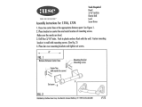
TREX SECLUSIONS
®
INSTALLATION GUIDE
ITEMS USED PER SECTION (6’ Tall)
BEFORE YOU BEGIN
TOOLS NEEDED
STEP 1: DETERMINE INSTALL METHOD FOR UNEVEN TERRAIN
□ Stakes
□ Pencil
□ String line
□ Tape measure
□ 12” Miter Saw (Recommended)
□ Circular Saw
□ Shovel or post hole digger
□ Drill
□ Wheel Barrow
□ 4 ft Level
□ Hammer
□ Spray Paint
□
2” Finish Nails / Nail Gun or
Composite Screws
□ Speed square
>> Confirm location of underground utilities with local providers before you dig.
>> Check local zoning laws, which may regulate the size and placement of your fence.
>> Apply for local permit as directed by local code.
A
B
C
D
E
F
G
1 Post Cap
1 Post
4 Brackets
1 Top Rail
13 Pickets for 6’long Kit
2 Bottom Rail Covers
1 Aluminum Bottom Rail
A
B
C
D
E
F
G
A
1
For uneven terrain, determine which method you will use to install your
panels:
This fence gradually “steps” up the slope so that each
section is the same length and the rails remain level. You will need to
fill in the gap below the fence with soil. The downhill post will need to
be set taller to allow attachment of the upper rail. Taller posts may be
required. When laying out fence (STEP 2) spacing between posts
must be measured horizontally and not parallel to the ground.
2
This fence follows the grade or slope with the rails
parallel to the ground. Taller posts are not required but the horizontal
post spacing may need to be reduced to avoid rails being too short.
Miter cut rails to fit grade. On extreme slopes pickets may require
cutting.
3
STEP METHOD:
SLOPING METHOD:
A fence can be easily transitioned to a different height.
Horizontal post spacing will need to be reduced (see fig.3 in STEP 2)
and top rail will need to be miter cut. Pickets will require cutting.
TRANSITION:
1
2
3
©2016 TFSC
19 Pickets for 8’long Kit
>> Wear proper safety protection for eyes and ears.

TREX SECLUSIONS
®
INSTALLATION GUIDE
STEP 2: LAY OUT FENCE LINE
A
C
B
Opening
Between
Posts
Gate
Posts on
Center
Panel
Size
Standard Panel
Large Panel
44-3/8”
63-7/8”
46-1/4”
65-3/4”
51-1/4”
70-3/4”
2 Standard Panels
2 Large Panels
44-3/8”
63-7/8”
91-1/2”
130-1/2”
96-1/2”
135-1/2”
1 Standard & 1 Large Panel 111” 116”
Gate Post Spacing
Fig. 2
Advanced Tips and Tricks:
STEP 3: DIG HOLES
30”
12”
A
A
A
C
D
E
B
C
D
E
74-1/2”
STEP 4: SET POSTS TO HEIGHT
0”
6”
12”
18”
24”
96”
94¼”
91½”
88”
83⅝”
Drop in
4 ft
Max on Center
6’Kit 8’Kit
4 ft Level
Fig. 3
Determine the amount of vertical drop in a 4’
horizontal distance by placing a 48” level on the
ground and raising it until it is level and then
measuring from bottom of the level to the ground.
Consult the chart to the right for maximum post on center.
0”
12”
24”
36”
48”
Ex. For 8’ kit, if ground drops 6” in 4’, then max centers is 94¼”.
When transitioning from one fence height to the next, use transition chart.
Ex. Sloping from a 6’ to a 3’ fence with 6’ kit, set post center at 52”.
Transitions
Drop
67½”
66½”
64⅜”
61¾”
58⅝”
96”
94”
90¾”
85½”
78¾”
Max on Center
6’Kit 8’Kit
67½”
65¼”
60¼”
52”
29”
73½”
73½”
TRANSITION
POINTS
A
B
73-1/2”
Mark location of all end and corner posts using spray paint. Place
stakes and string lines so that the string runs along the outside edge
of these posts.
Determine the location and size of each gate and mark the location of
gate post centers (see fig. 2 for proper spacing).
Mark the locations of the remaining post centers by measuring 67 1/2"
(for 6' long kits) or 96" (for 8' long kits) from the marks made in steps
A and B. This may leave a short section at the end. If ground is
slopping, or fence transitions to a different height, the posts may need
to be spaced closer together (see fig.3 for proper spacing).
For uniform post spacing, mark the location of the remaining posts in step C by
measuring the distance (in inches) between the marks made in steps A and B. Divide
these measurements by 67 1/2" (for 6' long kits) or 96" (for 8' long kits) and round up
to determine the number of sections. Now divide the distance between the marks by
this number (number of sections), this will be t
he distance between the posts.
Ex. For a 69’ fence line on flat terrain using an
8’ kit: 69 x 12 = 828” / 96” = 8.625 Now round
up = 9 sections. Now 828” / 9 = 92” on center.
6’ kit: 69 x 12 = 828” / 67.5 = 12.27 Now round
up = 13 sections. Now 828” / 13 = 63 5/8” o.c.
Dig holes for posts making sure not to disturb the stakes. Holes should be
12” in diameter and 30” deep (or as required per local codes or conditions).
Holes should be dug so that they allow for equal amounts of concrete on
all sides of posts.
If setting posts to height, set all end, corner and transition
posts (posts where ground changes slope) first. String a line
from the top of these posts to determine the height of the
remaining posts. Now, set the remaining posts so that the top
of these posts align with this string. Note: If posts are not being
set to exact height (i.e., cut to height after setting) insure that
posts are set to the proper depth as indicated in Step 3, then
string for height after all posts are set and follow Step 5.
Insert post int
o hole. typical finish post height for a 6’ fence
is 74-1/2” to top of post or 73-1/2” to bottom edge of crown
cap (if using 8’ posts, the post will be raised to height when
adding the concrete).
Fill hole around post with concrete mix to approximately 2”
below grade.
Level and plumb posts making sure post is
next to string but not touching.
Allow concrete to set as per manufacture’s
instructions before installing the rails and
pickets.
Property
Property
pin
Stakes For
Fence Lines
Holes
Marking For
Digging Post
Holes
Property
pin
Post
Location
Fig. 1
Gate Posts
Corner Post
End Post

74 1/2”
74 1/2”
TREX SECLUSIONS
®
INSTALLATION GUIDE
STEP 5: CUT POSTS TO HEIGHT
74-1/2”
73-3/8”
5-3/4”
Ex. If the drop measured above is 1-1/2”, then add 1-1/2” to the
measurements for the brackets on downhill side of the post. The
upper bracket would be 5-3/4” plus 1-1/2” = 7-1/4”. The bottom bracket
would be 73-3/8” plus 1-1/2” = 74-7/8”.
A
Locate transition posts (posts where ground changes slope)
and string lines 74-1/2” above ground. This will create a
reveal as shown below. Adjust your height if desired.
5C
To keep rails flowing smoothly on a slope, while string line is
still up, determine bracket slope adjustment (if any) by
holding a bracket on the uphill side of post so that the bracket
touches the string line. Make a small pencil mark at the bottom
of the bracket. Now hold a bracket on the downhill side of post,
once again just touching the string line, and make a small pencil
mark. Using a speed square, note the amount of vertical drop
between the two marks. This measurement should be added to
the measurements used for mounting the top and bottom rail
brackets in STEP 6B.
A
Using (4) 1-5/8” fence screws, attach the rail brackets to the post as follows:
B
Using a pencil and a speed square, draw a line where the
string line crosses the uphill side of the post. Transfer this
line around all four sides of the post using your speed
square. Cut post to height using a circular saw.
1-1/2”
5C
5B
STEP 6: ATTACH RAIL BRACKETS
B
6C
A
B
5-3/4”
7-1/4”
74-7/8”
73-3/8”
6D
D
Advanced Tips and Tricks:
74 1/2"
5B
Advanced Tips and Tricks:
TRANSITION
POSTS
5A
©2016 TFSC
2 1/4”
1/2”
2 1/4”
1 1/4”
Skip to Step 6 if posts have been set to height
FLAT or
PYRAMID
CAP
CROWN
CAP
Measure down from the top of the post 5-3/4”(or 4-3/4“ from the bottom of the
crown cap). This will mark the bottom of the upper bracket. Measure down from
the top of the post 73-3/8”(72-3/8” from the crown cap). This marks the bottom
of the bottom bracket. If fence is on a slope, adjust bracket placement as
indicated in Step 5C. Bracket should be centered on the post.
If the fence will run on an angle to the post, use rail bracket adapters to adjust
the bracket angle. Each bracket provides 22.5 degrees of adjustment. Mount
the adapter with two screws through the center holes into the post and then
run your 4 screws through the outer holes of both the bracket and the adapter
into the post.
C
More than one adapter can be used if necessary.

Advanced Tips and Tricks:
TREX SECLUSIONS
®
INSTALLATION GUIDE
STEP 7: CUT & INSTALL BOTTOM RAILS
STEP 8: CUT TOP RAIL
A
Measure between the post or for a more accurate cut, hold the
aluminum bottom rail next to the posts in line with the rail brack-
ets, with the deeper pocket facing down. Mark the bottom rail to
transfer angles to ensure accurate cuts. Cut the rail using a non-
ferrous metal cutting blade (Wear Eye Protection). Cut the rail
1/2” smaller to avoid scratching the posts during installation.
B
Repeat the procedure with two bottom rail covers (face
them in opposite directions), but do not cut them
shorter so you can maintain a tight fit. Cut the rail
covers using a circular saw or miter saw.
C
Slide the bottom rail covers over the bottom rail.
D
Slide the assembled rail over the bottom rail brackets.
A & B
C
D
A1
When dealing with a slope or complex angle, set your top rail
on top of your posts. Hold your speed square against the post
and mark the rail. Repeat on the other post.
A2
For a complex angle, mark the rail underneath where it crosses
the post. Repeat on the other post.
C
Test fit the top rail on the brackets. Leave in place while
cutting and fitting top rails for the remaining sections to
ensure everything fits properly.
A1
Bottom
A2
A3
Determine the miter angle by laying your speed square on the
side of the top rail in line with your mark. Make sure the pivot
point touches the bottom edge of the rail. Read the angle by
noting where the bottom edge of the rail crosses the gauge.
Set the miter angle of your compound saw to this angle.
A3
A4
A4
Determine the bevel angle by laying your speed square on the
bottom of the rail in line with your mark. Make sure the pivot
point touches the edge of the rail. Read the angle by noting
where the edge of the rail crosses the gauge. Set the bevel
angle of your compound saw to this angle.
B
Place the rail on your miter saw with the top side
against the fence. Line the blade up with your marks
and cut the rail. Repeat the process with the other end
(If using a circular saw, transfer mark around top cap
before cutting).
D
Remove the top rails and set aside until after the
pickets are in place.
A
It is easier to measure and mark your top rail before the pickets
are in place. Measure between posts or hold your rail next to
the post in line with the top rail brackets and mark the rail to fit.
A
PIVOT
POINT
PIVOT
POINT
ANGLE
ANGLE
©201
6 TFSC
B

TREX SECLUSIONS
®
INSTALLATION GUIDE
STEP 10: INSTALL TOP RAIL
STEP 11: INSTALL POST CAPS
A
Replace the top rail you set aside in STEP 8 by setting the top rail
over one bracket and gradually lower over the pickets while wiggling
the pickets so that they will slide inside the top rail as you lower it.
B
Secure the rail to the brackets using (2) 1-5/8” fence screws through
the top of the top rail.
B
A
Place post caps onto the posts (if not already attached).
B
Caps may be secured using adhesive or a finish nail.
A
C
Use a finish nail or a composite screw through the side of the top rail
into pickets to prevent picket movement.
B
STEP 9: INSTALL PICKETS
A
Notch the first picket in each section at a 45 degree angle, measuring 2” each
direction. This will keep the picket from interfering with the bracket. Do not notch
the last picket until you know which direction it will face. If the posts are set at the
max width on center, the first and last picket will face the same direction. For
shorter sections, the first and last pickets may face in opposite directions.
B
Insert the first picket into the bottom rail, and secure it
to the post using (3) 1-5/8” screws.
C
Insert pickets into the bottom rail, alternating their
orientation so that they interconnect.
D
Notch the last picket and secure it to the post. It may
be easier to remove the second to last picket and
reinsert it by sliding it down from above after the last
picket has been secured to the post.
A
B
D
2”
2”
Advanced Tips and Tricks:
A
B
C1
If all the pickets are not tightly
interlocked, the most efficient
way to secure the pickets is to
pull all but the last two pickets as
tight as possible and secure the
third to last picket through the
top and bottom rails with a finish
nail or a composite screw.
C2
Evenly space the loose picket
and secure through the top and
bottom rails with the finish nail or
composite screw.
TOP VIEW
SIDE VIEW
C1 C2
D
If needed, use a finish nail or a composite screw through the bottom
rail cover into pickets to secure. Shoot the nail through the top 1/4” of
the bottom rail cover to miss the metal bottom rail (or pre-drill through
aluminum if using a composite screw).
D
C
©2016 TFSC
Note: With composite materials, you may notice some color variation. To minimize the effects of any possible
color variation, take special care when installing pickets to group pickets of similar colors within a section.
Note: Instead of a finish nail or composite screw, a 1- 1/4”
exter. wood screw can be used before top rail is replaced.

Trex Fencing
Phone: 877-700-8739 Email: Info@TrexFencing.com
Designed for Beauty. Formulated for Quality. Engineered for Durability.
For drawings, technical specifications, and other architectural information,
please refer to our website:
trexfencing.com/trade-resources/technical-center/
Be sure to research local codes and other requirements for your area prior to
installing your fence. An installation preparation checklist is available on our
website:
trexfencing.com/start-project/plan-your-fence/fence-project-preparation-
checklist/
Electronic copies of this guide and guides for gate installations are located on
our website:
trexfencing.com/installation/
/