Page is loading ...

CHAMPION ELITE LOW PROFILE COOLER
INSTALLATION & OPERATION MANUAL
4000 RLD4
4000 CRLD4
Circle the model of your cooler and record the serial number.
Encierrre con un circulo el modelo de su enfriador y escribe el
número de série.
Serial Number:
Número de série:
TABLE OF CONTENTS
Safety Instructions .........................................................1
How Evaporative Coolers Work .....................................1
Installation .....................................................................2
Operation ....................................................................... 6
Air Balancing Methods ...........................................7
Maintenance ..................................................................8
Specication Tables ....................................................... 9
Troubleshooting .............................................................9
Illustrated Parts List
.....................................................10
Limited Warranty .........................................................12
Date of Purchase:
Fecha de compra:
READ AND SAVE THESE INSTRUCTIONS
SAFETY RULES
1. Read all instructions carefully.
2. Electrical connections should be done by a qualied electrician,
so that all electrical wiring will conform to your local codes.
3. Always turn OFF POWER and UNPLUG motor and pump inside
the cooler before installing or performing any maintenance.
4. Your cooler will run on either 120V or 240V A.C., single phase,
60 Hz (cycle) current.
5. Motor and pump have a grounded, molded plug and an automatic
thermal overload switch which will shut motor o when it
overheats. The motor will restart automatically when it cools
down.
WARNING: To reduce the risk of re or electric shock, do not use
this fan with any “solid-state fan speed control device.”
PN 110524-1 REV. 11-17
READ CAREFULLY ALL OF THIS MANUAL BEFORE INSTALLING THE UNIT
Evaporative cooling is nature’s way of cooling. When air is
moved over a wet surface, water is evaporated and heat is
absorbed. When stepping out of swimming pool with the
wind blowing, evaporative cooling makes you feel cool, even
though the air may be warm.
This unit works on the same principle. Air is drawn across
wet lter pads where the air is cooled by evaporation and then
circulated throughout the building. It is this combination of
cooled air and the movement of air over the skin which makes
it feel cool.
Unlike refrigeration systems which recirculate the air, an
evaporative cooler continually brings in fresh air while
exhausting old air. You are completely replacing the air every
2 to 4 minutes by opening windows or doors, by using Up-
Dux
®
ceiling vents, or a combination of both. The air is always
fresh, not stale, laden with smoke and odors as happens with
refrigerated air conditioning.
HOW EVAPORATIVE COOLERS WORK

110524-1
2
LOUVERED SIDE PANELS.
The louver panels have a locking latch on each top corner to secure it in place. To remove the louvered
panel you will need to loosen the latch screws on either side of the panel. Loosen the screws enough
to rotate the latch handle, but do not remove completely. Rotate the latch handle towards the center
of the louvered panel. Tilt the top of the louver panel outward away from the top pan and lift out from
cooler.
To reinstall the panel, rst insert the bottom of the panel into the bottom pan. Tilt the panel forward so
that it rests against the top pan. You will need to keep the latch handles rotated to the side to keep the lock from hitting the top
pan. Once the louver panel is in place, rotate the latch handle so that the handle is facing down. Tighten the screws to lock latch
and secure panel in place.
ELECTRICAL CONNECTION
WARNING: Electrical connections should be accomplished by a qualied electrician to ensure all electrical
wiring conforms to local standards.
WARNING: Follow all safety precautions when working with electrical power.
WARNING: Before proceeding with installation, ensure electrical power is disconnected until installation is
complete.
Standard Model 4000RLD4
Note: This unit comes with the motor and pulley installed. The unit can be controlled with a manual 6 position switch found at
a local hardware store, or with a thermostat such as Champion’s Masterstat
®
Wall Control Thermostat model #110423-2. For
thermostat installation refer to its operating manual. Follow the steps below for manual switch installation:
1. Determine a location on a wall inside the home for the 6 position switch.
2. Supply 120V or 240V power to switch, depending on motor and pump voltages.
3. Remove screws securing junction box to cooler cabinet.
4. Bring four conductors plus a ground from switch to cooler junction box.
CAUTION: Make sure to use correctly sized wire and follow all local electrical codes.
5. Connect the four conductor wires to the leads of the motor and pump receptacles located in the junction box. Follow the
connection diagrams for 120V or 240V installations.
INSTALLATION
PARTS AND TOOLS NEEDED:
• 5/32 Allen Wrench (for pulley installation)
• 7/16 Wrench or Crescent Wrench
• Phillips Screwdriver
• Sill cock or water valve and tubing
• Multimeter (for amp reading)
CAUTIONS:
Before installing the cooler, note the following items:
• Before installation, ensure your existing electrical system is rated for the additional amperage draw from unit.
• Installation inside attic areas is NOT recommended.
• If installing on brace, or existing construction, ensure structure will hold the operating weight of the cooler. (See specication
table for operating weight.)
• Ensure entire unit is suciently supported.
• We strongly recommend consulting a professional contractor if installation will require cutting through existing structure such
as walls or roof.
• Do not screw or drill into the bottom pan.
• Ensure all electrical work is accomplished to local standards. An electrician may be needed for correct and safe wiring.
WARNING: Disconnect all electrical service that will be used for this unit before beginning the installation
and DO NOT reconnect until installation is complete.
CAUTION: To minimize the potential of water entering building, roof penetration should be limited to the
size of the duct opening from the unit. This roof penetration must then be sealed properly. The overow
drain must be allowed to drain outside any curb or roof penetration.

110524-1
3
Contractor Model 4000CRLD4
Note: This unit comes with the motor, pulley, and thermostat control box installed. The unit is factory wired and for 120V power.
The supply power should be adequately protected against overloads and short circuits.
Supply Power to Unit
1. A disconnect switch (not included) should be installed near the unit.
2. Run a 2 conductor wire with ground from the power source to the disconnect switch box.
CAUTION: Make sure to use correctly sized wire and follow all local electrical codes.
3. Remove the screws securing the electrical junction box in the unit to gain access to the power lead wires.
4. Connect the power leads and ground wire from the unit junction box to the disconnect switch.
5. Reinstall the junction box to the unit.
Wall Thermostat Installation
1. Find a suitable location for the wall thermostat (away from sources of heat, sunlight, or ventilation, and between 4 and 6 feet
from the oor). The thermostat may be mounted to a standard electrical box.
2. Route an insulated three or four-conductor thermostat cable (or similar) from the Control Box inside the cooler to the
thermostat electrical box. This cable is not supplied.
WARNING: The thermostat cable should not be routed next to or enter the cabinet through the same inlet as the
power supply wire.
3. Connect the thermostat wires to the terminals on the back of the wall control and to the terminals located on the left side of the
control box in the unit. Make sure to follow the color code found next to each terminal.
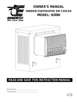
Blue/Black
White
Brown
Orange
Green
Green
Orange
White
Red
Black
PUMP
HIGH
LOW
COMMON
GROUND
= WIRE NUT
HIGH
LOW
COMMON
GROUND
Black
Green
White
Red
BLOWER MOTOR
PUMP
MOTOR
TO SWITCH
120 VOLT
COMMON
PUMP
MOTOR
BLOWER MOTOR
Red
Orange
Green
Black
GROUND
COMMON
LOW
HIGH
= WIRE NUT
GROUND
LOW
HIGH
PUMP
Black
Red
White
Orange
Green
Green
Orange
Brown
White
Blue/Black
TO SWITCH
240 VOLT
CAUTION: Recepta-
cles in junction box are
only for Motor and pump.
Do not plug anything
else into receptacle.
WARNING: Ensure
cooler cabinet is proper-
ly grounded to a suitable
ground connection for
maximum safety and
protection of equipment.
6. Reinstall junction box to cooler cabinet.
7. Plug motor and pump plugs into receptacles.
8. Follow switch electrical instructions for connecting the four conductors and power leads to switch.
Warning: Pump cord must be secured in retaining clip to prevent contact with water.
ELECTRICAL WIRING DIAGRAMS - STANDARD MODEL 4000RLD4

110524-1
4
WATER CONNECTION
Note: Do not connect the water supply to any soft water applications.
OVERFLOW INSTALLATION
1. Remove nut and place nipple through the hole in the pan with the rubber washer between the
pan and the head of the drain nipple.
2. Screw nut onto nipple and draw up tight against bottom pan.
3. Screw overow pipe into nipple. This overow pipe may be removed to drain pan when
necessary.
Note: A garden hose may be screwed onto the drain nipple to drain water away from the unit.
WATER SUPPLY INSTALLATION
A steady water supply is required for the operation of this cooler. A saddle valve or sillcock valve is
required to connect to a local water supply. These can be purchased from a local hardware store.
1. Install saddle valve to an interior cold water pipe, or install a sillcock valve to an exterior faucet
as shown.
2. Run ¼” plastic or copper tubing from the valve to the unit.
3. Install one end of tubing to water valve by placing nut and ferrule on tubing
and tightening the nut until water tight.
FLOAT VALVE INSTALLATION (Refer to illustration below)
1. Remove items 2, 3, 4, and 5 from oat.
2. Insert oat body through hole in the corner post or oat bracket as shown.
3. Install washer (2) and nut (3). Tighten to keep oat from turning. Place
nut (5) and ferrule (4) on water supply line. Connect to oat tting and
tighten until water tight.
Note: After installation is complete and water is turned on, the oat level will
need to be adjusted.
4. Bend rod to adjust oat. Water level should be about 1 inch below the top
opening of the overow pipe.
Faucet
Water Shut
O Valve
Sillcock With Std.
Hose Connection
Ferrule
Nut
Copper Or
Plastic Line
To Cooler
Rubber Washer
Overow Pipe
Nipple
Reservoir
Nut
Cold
Water
Pipe
Saddle
Valve
1/4” Tubing
Float
Corner
Post
Bracket
FAN MOTOR
PP
RECEPTACLE
DUMP
BROWN
THERMOSTAT
BLUE
RED
SWITCH LEADS
WHITE
LINK
WHITE
L1
RECEPTACLE
PCom
DRAIN PUMP
PUMP
ORANGE
WHITE/RED
WHITE/BLUE
GREEN
FLo
BLUE
N
RECEPTACLE
DP
ORANGE
FAN
ORANGE
BLACK
WHITE
WHITE
FHi
BLUE
NLink
CIRCULATING PUMP
DCom
BROWN
PWR. SUPPLY
VIOLET
BLACK/RED
=WIRE NUT
BLACK
FCom
120 VAC
GREEN
GREEN
SUPPLY
WHITE
BLACK
POWER
COOLER TERMINAL BOX
GREEN
RED
WHITE
DISCONNECT SWITCH
GROUND
SUPPLIED BY INSTALLER
ELECTRICAL WIRING DIAGRAM - CONTRACTOR 4000CRLD4 COOLER
1
2
3
5
6
4

110524-1
5
AMPERAGE DRAW AND BELT TENSION
CAUTION: No attempt should be made to completely install this unit without the aid of an electrician or
someone familiar with testing amperage draw. Failure to comply with these instructions may void your
warranty.
This unit is equipped with an adjustable motor drive pulley for adjusting the blower wheel speed to the proper loading for dierent
duct systems. It is important that the motor drive pulley is adjusted to correct size to ensure maximum air delivery without damage
to the motor. Be sure to follow these instructions carefully.
1. Ensure electrical connection of unit is complete and in accordance with all
safety standards and local requirements.
2. Reinstall inspection panels. Apply power, turn water and pump on and allow
cooler to run for a few minutes to wet pads.
3. Turn o the pump and check amperage and verify it conforms to amperage
listed on the specication label on motor.
• If amperage draw is less than motor rating, disconnect electrical power
and remove louvered sides. Unplug motor inside cooler, this will protect
you from someone turning the unit on while you are working inside. This
should be done for your safety. Adjust pulley to a larger diameter and
readjust belt tension. Plug motor in, install louvered side, and retest amperage
draw. Repeat this process until correct amperage draw is attained.
Note: Increasing motor pulley diameter increases amperage draw. Decreasing
motor pulley diameter decreases amperage draw.
CAUTION: DO NOT operate cooler with larger amperage draw than
specied on motor plate. Motor damage will occur.
4. Check belt tension after adjusting pulley. A 3 lb. force should deect the belt 3/4
inches. Readjust belt if needed by loosening adjustment screw, rotate motor until
you have the correct belt tension, then re-tighten screw.
SCALE BUILDUP PREVENTION
As water evaporates, minerals that were in the water will remain. Over time this
accumulation of minerals will cause scaling on the pads and in the reservoir. We
recommend the installation of either a bleed-o kit (included in standard 4000RLD4
unit) or a purge pump (installed in contractor 4000CRLD4 unit) to help prevent
scale build up and increase the life of the unit. A purge pump will drain the pan
every few hours of pump operation, to keep fresh water in the unit. A bleed-o kit
will continually bleed o a small portion of water while the pump is running allowing
fresh water to continually replace the old stagnate water. Follow the instructions
below for installing the bleed-o kit.
1. Cut the pump hose and insert the barbed ends of the bleeder tee into each
cut end.
2. Insert one end of the bleeder tubing onto the bleeder tee and run the other
end out of the cooler through the overow pipe.
Note: A restrictor clamp is provided which, if desired, may be installed onto the
bleeder tubing to restrict the amount of water being bleed o. The amount of water
to bleed o depends on the quality of the water in your area. Start with 1-2 gal/hr
and increase if needed.
Bleeder Tee
Bleed Tube
Restrictor
Overow Pipe
Pump Hose
BLEED-OFF KIT
Decrease
Amperage
Motor
Motor
Pulley
Blower
Pulley
Belt
3 Lb. Pressure
3/4 Inches
BELT TENSION

110524-1
6
OPERATION
NOTES: These coolers may be used without water for ventilation purposes. When outside air is cool (for example, at night) or
when humidity is high the water pump can be turned o.
To eliminate the delivery of hot air when starting the cooler, start the pump only for the rst few minutes, then turn on the blower
motor.
THERMOSTAT OPERATION (CONTRACTOR MODEL 4000CRLD4)
Automatic Operation (Cool Mode)
The fan and water pump are controlled automatically to achieve the desired comfort level.
This mode is activated by pressing the ‘Mode’ button until ‘Auto’ is displayed on the LCD. The ‘Mode’ button changes the control
from O to Auto to Manual and back to O.
The Set temperature (the target temperature for control) may be altered by repeatedly pressing or holding the ‘Up’ or ‘Down’
buttons. The LCD will display the ‘Set’ rather than ‘Room’ temperature for a short time after pressing the ‘Up’ or ‘Down’ button.
On starting or after the pump has been o for a period of time, the pump will start without the fan to allow the media to absorb
water. This is called Pre-wet and lasts for 2 minutes, indicated by ‘Pre-Wet’ ashing on the LCD. The Pre-Wet cycle can be
bypassed by pressing the ‘Fan’ button and then pressing the ‘Mode’ button until ‘Auto’ is displayed.
The thermostat will cycle the fan setting between High speed, low speed and o depending on room temperature. If the room
temperature drops 2 degrees below the set point temperature, the fan will turn o. At 1 degree above the set point temperature,
the unit will start on low speed. If the room temperature rises to 4 degreees above the set temperature, the fan will change to high
speed and will remain until the room temperature drops to 1 degree above the set point, where it will change to low speed.
The thermostat allows the operator to calibrate the room temperature reading. Pressing the up and down arrows simultaneously
for 5 seconds will enter the calibration mode. A temperature adjust setting of -3 to 3°F can be selected. After no activity for 5
seconds, the thermostat will exit the calibration mode and the room temperature will be adjusted by the selected value.
During automatic operation, the control performs a water purge cycle every 8 or 12 hours of pump operation. This interval can
be toggled between 8 or 12 hours by simultaneously holding the ‘Pump’ and ‘Fan’ buttons for 5 seconds. The selected interval is
displayed for a short time. This action also starts a manual dump cycle.
Manual Operation
The fan speed and pump are set by the user.
To activate the manual mode from the ‘O’ state, press the ‘Mode’ button until ‘Manual is displayed. If the control is in the ‘Auto’
mode, you can change to manual mode by pressing either the ‘Mode’, ‘Fan’ or ‘Pump’ buttons. Pressing the ‘Fan’ button changes
the fan from High to Low to O and back to High. Pressing the ‘Pump’ button changes the pump from On to O and back to On.
The LCD will display ‘Manual’ on the left and the fan and pump settings on the right. The fan speed will be displayed as Fan Hi
or Fan Lo. If neither are displayed the fan is o. The pump status will be displayed by the LCD as ‘Cool’ (if the fan is running)
or ‘Pre-Wet’ (if the fan is o). With the fan and pump both running ‘Cool’ will be displayed. If only the fan is running ‘Vent’ will be
displayed.

110524-1
7
Time Delay Operation (Timer Mode)
Delayed start or nish in ‘Auto’ or ‘Manual’ mode.
The ‘Timer’ button is used to set a delay period between 1 and 12 hours in 1 hour increments.
If the cooler is operating (in ‘Auto’ or ‘Manual’ modes) when the ‘Timer’ button is pressed, the delay period determines when the
cooler switches o. If the cooler is O when the ‘Timer’ button is pressed, the delay period determines when the cooler starts in
‘Auto’ mode. The set temperature will be the last setting when running in ‘Auto’ mode.
‘Timer Delay’ and the remaining time are displayed on the LCD while the timer feature is activated.
You can cancel the Timer function at any time by pressing the ‘Timer’ button. The ‘Timer Delay’ indicator will no longer be
displayed.
In The Event Of A Power Outage
When power is restored after a power outage, the thermostat will resume operation in the mode selected prior to the power outage.
If the timer mode is active, the time will be restored to the hour indicated prior to the outage.
AIR EXHAUST
For an evaporative cooler to be eective, there needs to be adequate exhaust. If there is not adequate exhaust, pressure and
humidity will build up in the building. You exhaust by opening doors or windows to allow the old stale air in the building to escape.
Attic exhaust dampers may also be installed to exhaust the air into the attic. The combination of attic exhaust dampers and a
thermostat can provide a completely automatic operation.
An often misunderstood concept of evaporative cooling is the amount of air that should be exhausted. How much should you open
your windows? The following two methods will help you determine the amount to open your windows.
WINDOW AREA/CFM METHOD
For proper air ow, allow an opening of at least 2 square feet (288 square inches) for each 1000 CFM rating of your unit.
Example: At 3640 CFM, model 4000RLD4 requires 7.3 square feet (1050 square inches) of opening (3320/1000 * 2 = 7.3).
Multiply the number of windows by window width in inches and divide this into the number of square inches required for your size
unit. This will give you the height to open windows. In this example, four 36 inch wide windows should be opened 7.3 inches each.
TISSUE SUCTION METHOD
1. Take a piece of tissue paper and cut it lengthwise into 3 equal strips.
2. Turn your cooler on high cool.
3. Open one window at least six inches wide in each room that you want to cool.
4. Take the piece of tissue paper and put it up against the screen of the open window furthest from the cooler discharge
opening. Let go of it. It will do one of three things.
IF: It falls down. THEN: CLOSE all of the windows one inch and try step 4 again.
IF: It plasters itself to the screen. THEN: OPEN all of the windows one inch and try step 4 again.
IF: It stays on the screen lightly. THEN: PERFECT. You are done. Enjoy your cooler.
Notes:
• When switching to low cool, you must re-balance your home. Repeat step 4.
• Once you balance your home you can cool some areas more than others by opening those windows
more and closing the others by the same amount. Repeat step 4 to make sure your home is still air balanced.

110524-1
8
MAINTENANCE
Regular maintenance on your cooler will increase performance and extend the life of your cooler.
WARNING: Before accomplishing any maintenance ensure power is turned o and the motor and pump are
unplugged.
START OF SEASON MAINTENANCE
Accomplish these basic steps before the temperatures require cooling in case you have to acquire replacement parts.
CLEAN OR REPLACE MEDIA
1. With power DISCONNECTED, remove louvered doors.
2. Inspect lter media. Scale buildup on the media will obstruct the airow and cause the media to be less absorbant. If there is a
lot of scale buildup, check the bleed or purge settings. The bleed-o may be plugged, or the purge cycle may need to be more
frequent. A dirty lter will be less ecient and will cause a decrease of cooling in the home.
3. If media is dirty, remove from the louvered side. Remove the top media support brackets, loosen the water trough screws and raise
water trough, then lift out media.
4. Clean the media with a garden hose. Light scraping may be required to remove mineral deposits. Do not use harsh detergents or
pressure washers in cleaning. Make every eort to keep the media intact.
5. The original media has a standard life of 5 years, but in areas with very high mineral content the media may have to be replaced
sooner. If cooling eciency is not adequte, replace the media.
6. When reinstalling existing or installing new replacement pads, we recommend using original equipment, MasterCool® media
replacement pads for highest cooling capabilites.
OIL BEARINGS
1. The blower bearings should be oiled each year with non-detergent 20/30 weight oil.
2. Locate and open the oil cup on each of the blower bearings and add a few drops of oil.
CLEAN PUMP
1. Pump should be cleaned at least once a year or more often if debris accumulates.
2. Unplug motor and pump from junction box, and disconnect pump distribution tube.
3. Using a screw driver, pry plastic retaining fasteners straight up out of the pump-mounting
bracket.
4. Slide the pump o the mounting bracket.
5. Extract pump from straining basket or netting and remove base of pump.
6. Clean pump, turn impeller to ensure free movement.
7. Remove pump spout and check for blockage.
8. Reinstall pump base and verify it is secure.
9. Before reinstalling pump, check water hose, bleeder line and water distributor tube to
ensure there is no blockage in any lines.
10. Reinstall the pump by sliding pump onto mounting bracket and reinserting the plastic
retainers to ensure pump stays in upright postion.
11. Reinstall pump water distributuion tube to the pump outlet spout, making sure it is
pressed onto spout securely.
CHECK BELT
1. Before unit is turned on, check that belt condition is good. If belt must be replaced, install same sized belt.
2. Verify belt tension is correct: 3/4” deection with 3 lbs of force.
END OF SEASON SHUTDOWN
The cooler should be prepared before any extended period of non use, and especially before winter shutdown.
1. Drain all water from unit, supply line and pump to ensure no damage occurs from freezing. Keep water line disconnected from both
unit and supply line.
2. Unplug motor and pump from junction box.
3. Clean unit.
4. Cover unit to protect nish for long periods of non use.
Impeller
Remove
Base
Blower Bearing
Oil Cup

110524-1
9
GENERAL SPECIFICATIONS
MODELS
WEIGHT (lbs) CABINET DIMENSIONS (in.) DUCT OPENING (in.)
SHIPPING OPERATING HEIGHT WIDTH DEPTH WIDTH HEIGHT
4000RLD4
4000CRLD4
218 305 30 1/2 41 1/4 41 1/4 17-3/4 17-3/4
MOTOR SPECIFICATIONS
MODELS H.P
MOTOR PN
SPEED VOLTS AMPS
WEIGHT (LBS)
PUMP MODEL #
PUMP AMPS DRIVE BELT P/N
4000RLD4
4000CRLD4
3/4 110449 2 115 10.5 21 110429 0.9 110212 (4L-570)
TROUBLESHOOTING GUIDE
PROBLEM POSSIBLE CAUSE REMEDY
Failure to start or no air delivery
1. No electrical power to unit 1. Check Power
• Blown Fuse or Tripped Circuit Breaker
• Electrical cord damage
• Replace fuse or reset breaker
• Replace Cord
2. Belt too loose or too tight 2. Adjust belt tension
3. Motor overheated 3. Determine cause of overheating
• Belt too tight
• Blower bearings dry
• Motor pulley diameter too large
• Adjust pulley tension
• Oil blower bearings
• Adjust pulley to correct diameter
4. Motor locked 4. Replace motor
Inadequate air delivery with cooler running
1. Insufcient air exhaust 1. Open doors or widows to increase air ow
2. Belt too loose 2. Adjust belt tension or replace if needed
3. Pads plugged/dirty 3. Clean pads
4. Motor underloaded 4. Adjust pulley
Water draining onto roof
1. Float arm not adjusted properly 1. Adjust oat
2. Overow assembly leaking 2. Tighten nut and overow pipe
Musty or unpleasant odor 1. Stale or stagnate water in cooler 1. Drain pan and clean pads
Motor cycles on and off
1. Low voltage 1. Check voltage
2. Excessive belt tension 2. Adjust belt tension
3.
Blower shaft and tight or locked
3. Unplug unit and oil or replace bearings
4. Bearings dry 4. Oil bearings
5.
Motor pulley diameter too large ,
causing motor overload
5. Adjust pulley so full load ampere
rating of motor is not exceeded.
Noisy
1. Bearings dry 1. Oil bearings
2. Wheel rubbing blower housing 2. Unplug unit, inspect and realign
3. Loose parts 3. Tighten loose parts
Inadequate cooling
1. Inadequate exhaust in house
1. Open windows or doors to increase air ow
2. Pads not wet 2. Check water distribution system
• Pads clogged
• Distribution tube holes clogged
• Pump not working properly
• Clean pads
• Clean tube holes
• Unplug and replace or clean pump
Excessive humidity in house 1. Insufcent air exhaust 1. Open doors or windows

110524-1
10
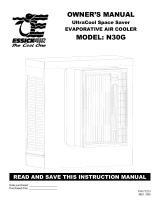
No. Description 4000 RLD4 4000 CRLD4
1. Top Pan .................................................................................................................................220905-005 220905-005
2. Bottom Pan ........................................................................................................................... 320908-005 320908-005
3. Louvered Side Assembly ......................................................................................................324111-106 (4) 324111-106 (4)
4. Water Trough / Canal De Agua ...........................................................................................226003-004 (4) 226003-004 (4)
5. Pad Set ................................................................................................................................. 310101-4 (4) 310101-4 (4)
6. Pad Retainers ....................................................................................................................... 224111-008 (12) 224111-008 (12)
7. Corner Post ........................................................................................................................... 324003-013 (4) 324003-013 (4)
8. Cut-O Plate ......................................................................................................................... 224004-002 224004-002
9. Blower Housing ..................................................................................................................... 324110-002 324110-002
10. Blower Wheel ........................................................................................................................ 16BW 16BW
11. Shaft, Blower Wheel ............................................................................................................. 110183 110183
12. Bearings, Blower Wheel Shaft .............................................................................................110351 (2) 110351 (2)
13. Pulley, Blower Wheel ............................................................................................................ 110275 110275
14. Drive Belt .............................................................................................................................110212 110212
15. Motor .................................................................................................................................... 110449 110449
16. Pulley, Motor ........................................................................................................................ 110278 110278
17. Motor Mount ......................................................................................................................... 314003-004 314003-004
18. Motor Mount Clip Set ..........................................................................................................314005-001 314005-001
19. Electrical Cord, Motor ...........................................................................................................110372 110372
20. Float Valve ............................................................................................................................ FL-C FL-C
21. Pump Mount .........................................................................................................................218001-031 218001-031 (2)
22. Pump ....................................................................................................................................110429 110429
23. Pump Retainer ..................................................................................................................... 110714 (3) 110714 (6)
24. Purge Pump ........................................................................................................................ - 110429
25. Pump Mount Extension Bracket ............................................................................................218001-033 218001-033 (2)
26. Pad Retaining Strap Fastener ...............................................................................................110611 (24) 110611 (24)
27. Tube, Water Delivery ............................................................................................................310716 310716
28. Over Flow Assembly ............................................................................................................110610 110610
29. Water Distributor Assembly ..................................................................................................3D-7 3D-7
30. Holder, Water Distributor ......................................................................................................110574 (8) 110574 (8)
31. Electrical Junction Box .........................................................................................................320106-003 320106-003
32. Receptacle, Motor ................................................................................................................110393 110393
33. Receptacle, Pump ................................................................................................................110361 (1) 110361 (2)
34. Latch Assembly (2 Per Side) ................................................................................................318124 318124
35. MasterStat Thermostat Controls ...........................................................................................- 110423-2
36. Liquidtight Conduit ................................................................................................................- 110816
37. Liquidtight Connectors ..........................................................................................................- 110817
38. Bleed-O Kit .........................................................................................................................310586 -
NOTE: Standard hardware items may be purchased from your local hardware store.
REPLACEMENT PARTS LIST
When ordering parts, please be sure to furnish the following information on all orders. Failure to do so may delay your order.
1. Cooler model number
2. Cooler serial number
3. Motor HP
4. Description and part number
5. Date of purchase

110524-1
11
PARTS DRAWING

110524-1
12
LIMITED WARRANTY POLICY
SALES RECEIPT REQUIRED AS PROOF OF PURCHASE FOR ALL WARRANTY CLAIMS.
This warranty is extended only to the original purchaser of this evaporative cooler when the unit is installed and used under
normal conditions against defects in workmanship and materials as follows:
• Two (2) years from date of sale on the cabinet components
• Five (5) years on the evaporative media, which is considered a disposable component
and should be replaced periodically.
• Eight (8) years on the bottom pan if water leakage should occur due to rust out
The manufacturer will replace the defective part/product, at its discretion. It is agreed that such replacement is the
exclusive remedy available from the manufacturer and that TO THE MAXIMUM EXTENT PERMITTED BY LAW,
THE MANUFACTURER IS NOT RESPONSIBLE FOR DAMAGES OF ANY KIND, INCLUDING INCIDENTAL AND
CONSEQUENTIAL DAMAGE OR LOSS OF PROFITS OR REVENUES.
Some states do not allow limitations on how long an implied warranty lasts, so the above limitations may not apply to you.
Exclusions from this warranty
We are not responsible for any incidental or consequential damage from any malfunction, accident, misuse, alterations,
unauthorized repairs, abuse, including failure to perform reasonable maintenance, normal wear and tear.
Alterations include the substitution of name brand components including, but not limited to media pads.
We are not responsible for any damage from the use of water softeners or treatments, chemicals or descaling materials.
We are not responsible for the cost of service calls to diagnose the cause of trouble, or labor charge to repair and/or replace
parts.
No employee, agent, dealer or other person is authorized to give any warranties or conditions on behalf of the manufacturer.
The customer shall be responsible for all labor costs incurred.
Some states do not allow the exclusion or limitation of incidental or consequential damages, so the above limitations or
exclusions may not apply to you.
How to obtain service under this warranty
Within the limitations of this warranty, purchaser with inoperative units should contact the dealer where you purchased the
cooler. If for any reason you are not satised with the response from the dealer, contact Customer Service at 800-643-8341
for instructions on how to obtain service within warranty as listed above.
This warranty gives the customer specic legal rights, and you may also have other rights which vary from province to
province, or state to state.
Register your product at www.championcooler.com.
Champion Cooler / Essick Air Products
5800 Murray St.
Little Rock, AR 72209
www.championcooler.com
/