3
110525
• Water Supply. Run a water supply line to the unit. The fl oat
valve requires a 3/8 inch tube connection. NOTE: Do not use
water supplied from a water
softener.
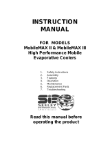
• Float valve. Install the fl oat
valve to the mount bracket in
the cooler (Fig. 4) and attach
water supply line. Note: 75/85
and 95 units come with the fl oat
valve installed. For the other
models, the fl oat is purchased
separately.
• Filling pan. Turn on water supply and check for leaks. Allow
water to fi ll to within 1” of top of pan. Loosen the screw on the
fl oat rod to adjust the fl oat and retighten the screw.
• Water troughs. Operate pump until pads are saturated. Check
each trough to see if water is evenly dispersed in the trough. If
they are not, loosen adjustment bolts and level trough. Retighten
bolts. Check to see that all pads are saturated with water and that
there are no dry spots or openings in the pads.
• Bleed-Off. Use of a bleed-off kit is recommended to prevent scale
build up by bleeding off small amounts of circulating water during
operation. Do not add any type of water treatment chemicals to the
water.
Pulley And Belt Adjustments
• Pulley adjustment. With an ammeter, check the motor amper-
age. Adjust the pulley until the amperage draw on the motor is
just below that specifi ed on the motor
nameplate. To adjust the pulley, loosen
the adjustment set screw and rotate the
sheave. Tighten the set screw so that
it is over a fl at area, otherwise thread
damage will occur. To increase amper-
age draw, increase pulley diameter.
To decrease amperage draw, decrease
pulley diameter (Fig. 5). Recheck belt
alignment.
CAUTION: When it is necessary to adjust pulley, amperage
of motor must be checked to make certain it does not exceed the
maximum allowed as stamped on motor specifi cation plate. Im-
proper pulley adjustment will overload and burn out motor.
• Belt tension. Loosen the motor
mount bolts and slide the motor
back until the belt is properly
tensioned. A 3 lb. force should
defl ect the belt 3/4 inches (see Fig.
6). Retighten motor mount bolts.
Do not adjust pulley to tighten
belt.
Maintenance
WARNING: Before doing any maintenance be sure to discon-
nect from power source. This is for your safety.
Spring Start-Up
• Belt tension. Check belt tension and readjust if needed.
• Oil bearings. The blower bearings and cooler motor in this unit
should be oiled with a few drops of non-detergent 20/30 weight oil
once each year. The motor does not need oil if it has no oil lines
for oiling. Motors that have no oil lines are lifetime oiled at the
factory and require no further oiling for the life of the unit.
CAUTION: Do not over oil. Over oiling can cause motor burn
out, due to excessive oil getting into motor winding.
• Change Pads. The pads should be replaced once or twice a season,
depending upon the length of the season. At the beginning and at
mid season a clean pad is more absorbent and effi cient and will
deliver substantially more cool air.
• Clean pump. Cleaning the pump is necessary once a year at start-
up. For your safety, disconnect from power source and unplug
pump. Remove the pump from the mount bracket. Remove the base
of the pump (Fig. 7). Clean the pump and turn the impeller to ensure
free operation. Remove the pump spout and check for any blockage.
After cleaning, reinstall the
base onto the pump. Reat-
tach the pump to the mount
in the cooler to ensure that
the pump will not overturn.
Do not forget to replace the
spout and water delivery tube
onto the pump outlet. The
pump has automatic reset
thermal protection. Pump
will operate normal again
after obstruction is cleared.
• Bleed off. Check bleed-off valve to be sure it is not clogged.
Winter Shut Down
• Drain water. Always drain all of the water out of the cooler and
water supply line when not in use for prolonged periods, and par-
ticularly at the end of the season. Keep the water line disconnected
from both the unit and water supply so that it does not freeze.
• Disconnect from power supply when not in use for extended
periods of time.
• Cover unit. To protect the life of the fi nish, a cover for the unit is
suggested in extended periods of non use.
By following the operating, installation, and maintenance sugges-
tions as outlined, you can get many years of effi cient and satisfac-
tory service from your cooler. In the event additional information
is desired, your dealer will be more than glad to assist you in every
possible way.
Remove
Fig. 7
Float Rod
Water Supply
Line
Washer
Nut
Ferrule
Nut
Fig. 4
Mount Bracket
Fig. 6
3 lb.
3/4 Inches
Decrease
Amperage
Fig. 5