Page is loading ...

IMPORTANT!
We are committed to the highest quality in the manufacture of this RACK IT UP! pot rack. The components of
each rack are carefully inspected before shipment.
However, in case there is a problem, PLEASE LET US HELP YOU FIRST. Do not return the item to where you
purchased it. First, call us and explain what is missing or wrong. We will do our best to help with any question or
problem you have—and as fast as possible.
Call us TOLL FREE 1 (877) 362-5863 and ask for customer service. Thank you!
TOOLS NEEDED - We provide all tools required for assembly: hex wrench, fastener hardware (nuts, bolts).
Note under attaching instructions on page 3 of this booklet, the list of tools you will need to provide.
RACK IT UP! 1 Year Limited Warranty
This product is warranted to be free of material defects for a period of five years from the date of purchase. Your exclusive
remedy is the repair or replacement of the defective product, and shall be subject to the following conditions: (1) You send
a notice of any defect to RACK IT UP! within the warranty period, and (2) You return the defective product, to RACK IT
UP!, 24 Colwell Street, Port Hadlock, WA 98339, postage prepaid, within 20 days following receiving a return authoriza-
tion number. (A return authorization number may be obtained from RACK IT UP! by calling the number at the bottom of
this booklet.) There are no other warranties expressed or implied. There are no warranties of merchantability or fitness for
a particular purpose. RACK IT UP! specifically disclaims any and all incidental or consequential damages arising out of
purchase, installation or use of this product.
RACK IT UP! ™ is a trademarked brand - All rights reserved.
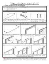
Ov P Rack
Mod MPO

Item No. Description Qty. Item No Description Qty.
3A Side bar 22” 4 thru holes 2 28B Barrel nut 11
4A Oval end 2 19A 1/4” Bolt hook - 4” 2
5 Hang tab 2 0 Installation hardware
6 Curved arm 4 15 S-hook 2
25A Pot hook straight 6 20 Wood Screw Hook - 4” 2
25B Pot hook angled 6 26A Hex wrench 2
28A Barrel Bolt 11 27A Toggle 2
7A Grid Bracket 3 8A Grid—6” x 22” 2
MISSING A PART?
Please call our TOLL FREE
SERVICE CENTER
1 (877) 362-5863
How To Assemble Your Pot Rack
TIP!
FIRST, REMOVE PAINT FROM BOLT HOLES. Because the powder coat finish applied at the
factory also adheres to the inside of bolt holes, pushing a bolt through it during assembly may be difficult. There-
fore, before connecting parts, we recommend that you check to see that bolts slip easily through all holes. If they
do not, carefully clear paint from holes in side bars, ends and arms using a small knife.
SECOND, be certain that barrel nuts and bolts screw together easily BEFORE beginning assembly. Residue
from the black finish may cause some bolts to stick a bit, therefore use the two hex wrenches enclosed (one for
each end of the barrel) and screw them together to clear away extra paint.
TIP! SAVE TIME AND HASSLE.
PLEASE READ ENTIRE INSTRUCTIONS
BEFORE BEGINNING ASSEMBLY.
STEP 1: LAYOUT PARTS
On a table lay out all parts as shown in the exploded view above.
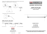
STEP 2: CONNECT MAIN BODY PARTS
TIP!
It is easiest to attach the pot rack parts when you insert the barrel nut (28B) from the INSIDE of the pot rack body,
then screw the barrel bolt (28A) into 28B from the OUTSIDE.
Temporarily connect two Oval ends (4A) and the 2 side bar(3A) by inserting a barrel nut and bolt (28A, 28B) through the
top hole at each of four corners. This will cause body of pot rack to stand on edge. Be certain side bar (3A) is on the IN-
SIDE when connected.
STEP 3: ATTACH FIRST ARM
TIP! It is easiest to attach arms when the corner of the pot rack to which you are connecting the arm hangs slightly past the
edge of the table. That provides clearance for the flared end that extends below the body of the rack.
Now remove the barrel bolt (28A) from one of the corners, keeping barrel nut (28B) in position. Place a curve arm (6--two
-hole end) on the OUTSIDE of the body. Align the three pieces over the barrel nut [side bar (3A) on inside, oval end (6) in
middle, arm (4A) on outside] then screw the barrel bolt (28A) into nut and loosely tighten.
Repeat for lower hole. Do not tighten barrel bolts firmly until all bolts are in place.

STEP 4: ATTACH OTHER THREE ARMS
Repeat STEP THREE for remaining arms.
STEP 5: HANG TABS
Position two hang tabs (5) at tops of each arm pair, insert barrel nuts/bolts and loosely tighten.
STEP 6: LEVEL POT RACK ON TABLE
Place assembled rack squarely on table and adjust all parts to be certain they are level and straight.
Then tighten all bolts firmly.
STEP 7: PLACE BRACKETS
Position brackets on pot rack as shown in illustration
STEP 8: LAY GRID PANELS ACROSS BRACKETS
Position panels side by side in pot rack as shown in illustration. Each panel is 22” x 6”. Place 6” bar side DOWN to run
parallel with brackets thus minimizing side slippage while in use.
TOOLS NEEDED:
Provided: Installation hardware (anchors, bolt hooks, screw hooks, S-hooks)
You will need: tape measure, pencil, drill and ½” drill bit, hammer and nail
STEP 1: LOCATION
Decide where you want to place your pot rack. Also consider the height of the ceiling where the pot rack will hang.
(See STEP 2 below.)
On the ceiling, mark two points 20-3/4” apart where the top of rack arms (at hang tabs) will attach to ceiling bolt hooks. Then
tap a small nail through each mark to be certain a joist is not in the way. (NOTE: because your pot rack includes super-strong
new-technology anchors, you DO NOT need to locate and bolt to ceiling joists. See more info under STEP 3 below.)
STEP 2: HEIGHT
What is the ideal height for your pot rack? Decide who will be the primary cook using the pot rack. The bottom of your longest
pan (usually a 10” or 12” skillet) should be easily reachable, about 6 inches above the cook’s head. Make sure the cook can
also reach the shortest pots.
This pot rack is designed for a 9-foot ceiling, a common height in many kitchens. If your ceiling is HIGHER than 9 feet, you
may want to consider adding chain to lower the rack to the ideal height. (Buy chain at a hardware store or contact our Custom-
er Service department.)
If your ceiling is LOWER than 9 feet, hanging pots may interfere with views through the kitchen, therefore you may want to
consider our Low-Ceiling Arms (a RACK IT UP! accessory) to raise the rack another 9-10”.
STEP 3: INSTALL DRYWALL ANCHORS—DO NOT TEST TOGGLE! ONE TIME USE ONLY!!!
RACK IT UP!’s drywall togglers eliminate the need to bolt your pot rack to a stud. The steel anchors are very strong and when
installed in drywall each drywall anchor holds about 200 lbs. Two anchors hold about 400 lbs., many times the weight you will
likely hang from your pot rack.
See Back of this Booklet for Toggle Instructions.
INSTALL IN WOOD
If you need to install one or both sides of your rack in wood, use one or two of the wood screw hooks screws (20) included.
See back page of booklet under Step 1.
How to Attach Your Pot Rack to the Ceiling
RACK IT UP
24 Colwell Street, Port Hadlock WA 98339
TOLL FREE (877) 362-5863
CLEANING
Your pot rack has a durable powder coat finish designed to provide years of protection. Cleaning is done easily using soap and
a damp cloth. Dry thoroughly after cleaning.
PAINTABLE Want a different color? The finish on this pot rack can be spray painted any color. We recommend Rustoleum
“Hammered” colors for their metal-like finishes, however any quality spray-can paint may be used. See a paint retailer for
guidance.

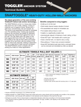
TOGGLER® brand SNAPTOGGLE® Toggle Bolt Installation Instructions
DO NOT attempt to test the snaptoggle as you will be unable to use it. Should
you need additional snaptoggles, you may purchase them at Lowes or find a
local resource on www.toggler.com
IMPORTANT! If your house is older (maybe a Victorian?) with lath board plaster ceilings and walls, DO NOT use the
new drywall anchor system. Old lath board plaster walls are not strong enough to hold drywall anchors. You must at-
tach the pot rack to wood joists with 4” wood hook/screws (included with your pot rack).
1) Using an electric drill with ½” bit, drill a hole at each of your marked
points. Hold metal channel flat alongside plastic straps
and slide channel through hole. Minimum clearance behind ceiling
should be 1 ⅞”.
NOTE: If a wood joist happens to be located at one of those points, use one of
the
4” wood screw hooks provided and screw it into the joist. (Pre-drill a hole in the
joist so the hook is easier to screw into the hole.)
We also understand--if you prefer, you can use the two wood screw hooks pro-
vided and drive them into the joists so you’re confident with the strength of the
attachment. However, to do so will likely require placing a cross bar (not includ-
ed)
above the ceiling which will often necessitate a carpenter’s services.
2) Hold ends of straps between thumb and forefinger and pull toward you until
channel rests flush behind drywall. Slide plastic cap along straps with other
hand until flange of cap is flush with the ceiling
.
3) Bend straps at ceiling by pushing side to side, snapping
off straps level with flange of cap.
4) Insert screw hook and tighten until flush, then stop.
NOTE: If you are also installing Trim Ceiling Covers (a RACK IT UP accessory), see pack-
age instructions before inserting and tightening bolt/hook.
Toggler ® Independent Lab Results
(anchor load before failure per attachment point)
TENSILE SHEAR
½” drywall - 265 lbs. ½” drywall - 241 lbs.
⅝ “ drywall - 356 lbs. ⅝” drywall - 324 lbs.
Industry safety standards recommend ¼ of ultimate test load
That’s’ it – You are now ready to hang your new pot rack!
Ceiling
Installation of Drywall Anchors
U.S. Patent no. 6, 161,999 and foreign counterparts thereof and of 4, 650, 386. Other patents pending. TOGGLER and SNAPTOOGLE are worldwide registered trademarks of Mechanical plastics Corp
/