Gossen MetraWatt METRISO PRIME Operating instructions
- Type
- Operating instructions

METRISO PRIME
High-Voltage Insulation Tester With Battery or Crank Generator Operating Mode
3-349-820-37
3/6.18
Option Z580A
Crank Generator
Operating Instructions

2 GMC-I Messtechnik GmbH
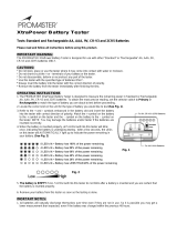
1 Selector switch for test voltage, battery test and power supply inter-
ruption
2 RANGE key for measuring range selection
3 Ω indicator LED – green: measurement OK
– off: invalid measurement,
battery too weak
4 LED lit: measuring range or scale up to 1 TΩ is selected
5 LED lit: measuring range or scale up to 100 MΩ is selected
6 Adjustor screw for mechanical zero adjustment
7 Selector switch for voltage or insulation resistance
measurements
8 Analog display
9Test prod for – measurement cable with safety cap
10 Test prod for + measurement cable with safety cap
11 Guard cable connector jack (accessory Guard 5000A (Z580C))
12 Battery or crank generator module
3
457
8
11
12
2
1
Attention!
!
Connect accessory 5 m extension
cable Leadex 5000 (Z580D) only
with positive measurement cable!
6
9
10

GMC-I Messtechnik GmbH 3
Contents Page
1 Sicherheitsvorkehrungen ................................................................ 3
2 Verwendung .................................................................................... 5
3 Inbetriebnahme ............................................................................... 5
3.1 Batterien einsetzen .........................................................................................5
3.2 Batterien testen ..............................................................................................5
3.3 Prüfgerät ein- und ausschalten ........................................................................5
3.4 Analoganzeige ................................................................................................6
4 Messen von Gleich- und Wechselspannungen ............................... 6
5 Messen des Isolationswiderstandes ............................................... 6
5.1 Messvorgang ..................................................................................................6
5.2 Beurteilung der Messwerte ..............................................................................7
5.3 Messung mit Guardleitung (mit Zubehör Guard 5000A) .....................................8
6 Technische Kennwerte ................................................................... 8
7 Wartung ........................................................................................ 10
7.1 Batterien ......................................................................................................10
7.2 Gehäuse .......................................................................................................10
7.3 Messleitungen ..............................................................................................10
7.4 Instandsetzung, Austausch von Teilen und Rekalibrierung des Gerätes .............11
8 Betrieb mit Kurbelinduktor Z580A ................................................ 11
8.1 Einsetzen des Kurbelinduktors .......................................................................11
8.2 Bedienen des Kurbelinduktors ........................................................................11
8.3 Messen des Isolationswiderstandes im Kurbelbetrieb ......................................11
8.4 Entladen des Prüfobjektes .............................................................................12
8.5 Spannungsmessung im Kurbelbetrieb ............................................................12
8.6 Technische Kennwerte ..................................................................................12
9 Zubehör (optional) ........................................................................ 12
10 Reparatur- und Ersatzteilservice
Kalibrierzentrum und Mietgeräteservice ...................................... 13
11 Produktsupport ............................................................................. 13
1 Safety Precautions
This instrument fulfills the requirements of the applicable EU guidelines
and national regulations. We confirm this with the CE marking. The rele-
vant declaration of conformity can be obtained from GMC-I Messtechnik
GmbH.
The METRISO PRIME insulation tester is manufactured and tested in
accordance with the following standards:
IEC 61010-1:2010, EN 61010-1:2011, VDE 0411-1:2011
IEC 61557-1, -2, DIN EN 61557-1:2007, -2:2008
VDE 413-1:2007, -2:2008
Hand-held probe assemblies: IEC61010-031:2015,
DIN EN 61010-031:2016, VDE 0411-031:2016
For testing and measuring circuits: IEC61010-2-030:2010,
DIN EN 61010-2-030:2011, VDE 0411-2-030:2011
In order to maintain flawless technical safety conditions and to assure safe
use, it is imperative that you read the operating instructions carefully and
thoroughly before placing your instrument into service, and that you follow
all points contained therein.
Opening of Equipment / Repair
The equipment may be opened only by authorized service personnel to
ensure the safe and correct operation of the equipment and to keep the
warranty valid.
Even original spare parts may be installed only by authorized service per-
sonnel.
In case the equipment was opened by unauthorized personnel, no war-
ranty regarding personal safety, measurement accuracy, conformity with
applicable safety measures or any consequential damage is granted by
the manufacturer.
Repair and Parts Replacement by Authorized Service Personnel
Voltage conducting parts may be exposed when the instrument is
opened. The instrument must be disconnected from all sources of voltage
before repair or replacement of parts. If the repair of an open, live instru-
ment cannot be avoided, this may only be performed by trained personnel
who are familiar with the dangers involved.

4 GMC-I Messtechnik GmbH
Errors and Extraordinary Strains
If it may be assumed that the instrument can no longer be operated safely, it must
be removed from serviced and secured against unintentional use. Send the instru-
ment to the Repair and Replacement Parts Service Department; see Chapter 10,
page 13. Safe operation can no longer be relied upon,
• if measurement cables are damages,
• if the instrument demonstrates visible damage,
• if the needle gauge no longer responds,
• if one of the LEDs is defective,
• if the instrument no longer functions,
• after lengthy periods of storage under unfavorable conditions.
Observe the following safety precautions:
• The instrument may only be operated with batteries or storage batter-
ies. Mains driven power packs are not permissible, because the use
of such is life endangering.
• Be prepared for the occurrence of unexpected voltages at devices
under test. (For example, capacitors can be dangerously charged.)
• Make certain that measurement cables are in flawless condition, e.g.
no damage to insulation, no creases, no interruptions etc.
Attention!
Do not touch the test prods or the device under test during
voltage testing! High-voltage of up to 5kV is present!
Attention!
Accumulation of Moisture:
An accumulation of moisture on
the tester, on the measurement cables or on the DUT must be
avoided, because leakage currents may be caused by high-voltages
at exposed surfaces. Even isolated components may carry high-
voltages.
Note
Overvoltage Influence: If the reversible fuse (PTC thermistor)
responds to an overvoltage or an extraneous voltage, measure-
ment may not be resumed immediately. A cool-down period of
approximately 2 minutes must be observed.
Using the test probes (Electrical Safety)
Attention!
Measurements per DIN EN 61010-031 may only be per-
formed in environments in accordance with measuring cate-
gories III and IV with the safety cap attached to the test probe
at the end of the measurement cable.
In order to establish contact inside 4 mm jacks, the safety caps have to be
removed by prying open the snap fastener with a pointed object (e.g. the
other test probe).
Meaning of symbols on the instrument
Warning concerning a point of danger
(Attention: observe documentation)
Caution: high-voltage!
A life endangering high-voltage of up to 5 kV
is present at the test prods.
CAT II/III/IV Measurement category II/III/IV device
Continuous double, or reinforced insulation
This device and the inserted (rechargeable) batteries may not be
disposed of with the trash. For information regarding the WEEE
mark can be accessed on the Internet at www.gossenme-
trawatt.com by entering the search term ’WEEE’.
Indicates EU conformity
!
Maximum rated voltage 300 V
600 V
1000 V 5000 V
Measuring category
CAT IV CAT III CAT II
—
With safety cap attached
••——
Without safety cap
— — ••
!
!

GMC-I Messtechnik GmbH 5
2 Applications
The METRISO PRIME insulation tester complies with regulation
IEC 61557/EN 61557/VDE 0413 “Measuring and Monitoring Equipment
for the Testing of Electrical Safety in Systems with Nominal Voltages of up
to AC 1000 V and DC 1500 V” Part 2, insulation resistance testers.
It is suited for the measurement of insulation resistance for devices and
systems in a voltage-free condition with nominal voltages of up to 1000 V.
It is also suited for the measurement of insulation resistance of up to 1 TΩ
with open-circuit voltages of up to 5000 V.
Additionally, the tester is equipped with a 2000 V measuring range for
direct and alternating voltages. This is especially advantageous for the
testing of DUTs for the absence of voltage, and for the discharging of
capacitive DUTs.
3 Initial Start-Up
For initial start-up of the METRISO PRIME with crank generator or of the
METRISO PRIME with accessory crank generator module see Chapter 8
and Chapter 3.4. For initial start-up of the METRISO PRIME with battery
operation mode see Chapter 3.1 to Chapter 3.4.
3.1 Battery Installation
Attention!
!
Before opening the battery compartment (green side panel) be
absolutely certain that the function selector switch is set to the
“V” position, and that the range selector switch is set to the “OFF/
V” position, and that the device is completely disconnected from
all external power circuits.
Ð Unscrew and remove the battery compartment.
Ð Remove the battery clip.
Ð Pull the battery holder out of the battery compartment.
Ð Insert 6 commercially available 1.5 V type IEC R20 or IEC LR20 bat-
teries or storage batteries (single cell) into the battery holder with cor-
rect poling as indicated by the symbols.
Ð Push the battery holder back into the battery compartment.
Ð Push the battery clip back over the contacts making certain that cor-
rect poling is assured.
Ð Return the battery compartment to the housing in the correct direc-
tion (labeling must be legible) and fasten with screws.
3.2 Testing the Batteries
After the batteries have been installed, or if the Ω indicator LED fails to
light up during insulation resistance measurement, the batteries should be
tested. For battery testing the range selector switch must briefly be set to
the position. Deflection of the needle gauge within the scale for the
battery test indicates the condition of the batteries or storage batteries at
an average load of 1000 V test voltage. The position of the function selec-
tor switch need not be taken into consideration. The left end of the scale
represents minimum required supply voltage, and the right end represents
maximum available supply voltage.
Note
If the needle only moves into the minimal supply voltage range,
several measurements can still be performed for test voltages of
less than 1000 V, because the battery test is conducted with the
same load as is used for a test voltage of 1000 V.
3.3 Switching the Tester On and Off
As long as the function selector switch is set to Ω, and the range selector
switch is not in the OFF/V position, the tester remains activated. For pur-
poses of transport and maintenance we recommend that the function
selector switch be set to the V position, and the range selector switch to
the OFF/V position, in order to prevent unintentional activation of the tes-
ter.
Note
Be certain that the grip on the function selector switch points
exactly to “V” or “Ω”. No intermediate selector switch positions
have been defined, and inaccurate switch positioning leads to
meaningless measurement results. This is especially important
during discharging of capacitive devices under test, because volt-
ages are not displayed in intermediate selector switch positions.

6 GMC-I Messtechnik GmbH
3.4 Analog Display
Logarithmic representation of the upper resistance scale allows for quick
recognition of the magnitude involved.
In order to achieve the required accuracy for testing of protective mea-
sures, the RANGE key allows for switching to the expanded lower limit
measuring range of 100 kΩ ... 100 MΩ.
The orange colored LEDs, (4) and (5), at the right end of the scale indicate
which of the two resistance measuring ranges is currently active.
The Ω indicator LED lights up green to confirm correct insulation mea-
surement. If this LED does not light up, test voltage has not been
achieved. In this event a battery test is advisable.
The two lower scales are for voltage measurement and battery testing;
see Chapter 3.2.
4 Direct and Alternating Voltage Measurements
Direct voltages and sinusoidal alternating voltages with frequencies rang-
ing from 15 to 500 Hz can be measured with the tester. Deflection of the
needle at the instrument is always positive for direct voltage measure-
ments, regardless of polarity at the connections. Alternating voltage is
indicated as an effective value.
Voltage measurements are used to test for the absence of voltage prior to
insulation resistance measurements, as well as for the automatic dis-
charge of capacitive devices under test. The voltage drop can be
observed at the display.
Note
Voltage measurement can always be performed with the function
selector switch in the “V” position, regardless of the position of the
range selector switch (even without batteries).
Ð Set the function selector switch to the “V” position.
Ð Check to see that the needle points to “0” in the V scale when the test
prods are not connected. Reset the needle as required with the ad-
justor screw for mechanical zero adjustment.
Ð
The position of the range selector switch has no influence on voltage mea-
surements, although we recommend setting it to the OFF/V position.
Ð Contact the measuring points with both test prods.
Ð Read the measurement value at the V scale.
Note
Voltages of greater than 2000 V may not be applied. Input resis-
tance for the voltage measuring range is equal to 5 MΩ.
5 Insulation Resistance Measurement
Be certain that the device under test is voltage-free before performing
measurements; see Chapter 4.
For measurements within a range of 100 GΩ (10 GΩ) ... 1 TΩ, the guard
cable should be used; see Chapter 5.3, page 8.
5.1 Measurement Procedure
Ð Set the function selector switch to the Ω position, in order to activate
test voltage.
Ð A range of either 10 kΩ ... 1 TΩ or 100 kΩ ... 100 MΩ can be pre-se-
lected with the RANGE key.
Ð Select the required nominal voltage of 100 V, 250 V, 500 V, 1000 V,
1500 V, 2000 V, 2500 V or 5000 V with the range selector switch de-
pending upon the nominal voltage of the DUT.
When lit, the LED (4) indicates that the upper limit measuring range of
10 kΩ ... 1 TΩ has been activated.
Ð Contact the measuring point with both test prods and wait until the
needle has come to rest. Depending upon the DUT this might take
only a few, or up to 30 seconds, if, for example, large capacities (long
cables) must be charged.
Ð Read the measurement value from the upper scale.
If the Ω indicator LED (3) lights up green, the insulation measurement
is valid. If this LED does not light up, test voltage has not been
achieved. In this event a battery test is advisable; see Chapter 3.2,
page 5.
Ð In order to achieve the required accuracy for testing of protective
measures, select the high resolution range, 100 kΩ ... 100 MΩ, with
the help of the RANGE key. The LED (5) lights up.
Ð Contact the measuring point with both test prods once again.
Ð Read the measurement value from the lower scale.

GMC-I Messtechnik GmbH 7
Attention!
!
Contact Hazard
Do not touch the conductive ends of the test prods when the in-
strument has been activated for the measurement of insulation
resistance.
This may cause current to flow over your body, which, although it
does not reach life endangering levels, causes a clearly discern-
ible shock.
When measurements are made at capacitive devices under test,
e.g. cables, the DUT may be charged with voltages of up to ap-
proximately 5000 V, depending upon selected nominal voltage.
Contact with the device under test after measurement is, in this
event, life endangering!
Safe Discharge
For this reason the DUT must be discharged in a controlled fash-
ion by switching to V and contacting the DUT with the test prods
until the measurement display indicates 0 V. Do not reverse the
poles of the DUT during discharging, because internal overvolt-
age protection would otherwise be triggered. If the capacity to be
discharged is greater than 3 μF, the poles may absolutely not be
reversed, because the device might otherwise be damaged.
Note
Overvoltage Influence
If the reversible fuse (PTC thermistor) responds to an overvoltage
or an extraneous voltage, measurement may not be resumed
immediately. A cool-down period of approximately 2 minutes must
be observed.
5.2 Evaluation of Measurement Values
In order to assure that insulation resistance values do not fall below those
required by DIN VDE regulations, insulation tester inherent deviation and
influence errors must be taken into consideration. Required minimum dis-
play values for insulation resistance which take maximum operational
measurement deviation of the METRISO PRIME into consideration (under
nominal conditions of use) can be determined with the following table.
These are the minimum values which must be displayed, in order to
assure that actual values do not fall below the required limit values. Inter-
mediate values can be interpolated.
The table is valid for test voltages ranging from 100 V ... 1000 V.
Scale, 100 kΩ ... 100 MΩ
Limit Value
[kΩ]
Display Value
[kΩ]
100 130
200 260
300 400
400 550
500 700
Limit Value
[MΩ]
Display Value
[MΩ]
11.3
22.6
34
45.5
57
10 13

8 GMC-I Messtechnik GmbH
5.3 Measurements with the Guard Cable (with Accessory Guard 5000A)
The measurement of very high impedance resistances presupposes
extremely small measurement currents, and can be rendered problematic
by influences such as electromagnetic fields, moisture or surface currents.
For this reason, the measurement set-up must be implemented in an
accurate fashion.
For measurements within a range of 100 GΩ (10 GΩ) ... 1 TΩ, a guard
cable must be used in order to prevent the distortion of measurement
results caused by surface currents. The guard rings prevent current at the
surface of the insulation material from flowing from the +measurement
cable to the –measurement cable, instead of through the insulation mate-
rial itself.
Ð Insert the guard cable plug into the appropriate jack at the tester.
Ð Plug the crocodile clip onto the guard cable test prod.
Ð Clip the crocodile clip onto the guard ring located between the two
measuring points of the insulation material to be measured.
Ð See Chapter 5.1, page 6 for measurement procedures.
Note
The following materials can be used as guard rings:
aluminum foil, copper foil or metal tubing clamps.
6 Characteristic Values
Insulation Resistance
ShortCircuit Current I
K
1.3 mA
Direct and Alternating Voltage
Protective Devices
1)
with reference to scale length 97.5 mm (100 MΩ range) or 109.8 mm (1 TΩ range)
2)
PTC thermistor cool-down period until start of new measurement:
at least 2 minutes must be observed!
+Measurement Cable
– Meas. Cable
Guard Cable
Conductor
Insulation
Material
Guard Rings
Contact Ring
Measuring
Range
Nominal
Range of Use
Nominal/Test
Voltage
U
N
/ U
T
Nom./Test
Current
I
N
/ I
T
Intrinsic Un-
certainty
1)
Measuring Un-
certainty
100 kΩ ...
100 MΩ
100 kΩ ...
10 MΩ
100 V
250 V
500 V
1000 V
1mA
± 2.5%
±30%
of measured
value
10 kΩ ... 1 TΩ
100 kΩ ...
100 GΩ
100/1500 V
250/
2000 V
500/
2500 V
1000/5000 V
1mA/0.7mA
1mA/0.5mA
1mA/0.4mA
1mA/0.1mA
± 5%
Measuring Range Frequency Internal
Resistance
Max. Allowable
Voltage
Intrinsic
Uncertainty
1)
0 ... 2000 V DC/AC 15 ... 500 Hz 5 MΩ
2200 V DC/AC
max. 10 s
±5%
Terminal Internal
Resistance
Max. Allowable
Voltage
Protective Device
–Measurement
Cable
—
to +meas. cable/
to guard cable:
2000 V DC/AC
max. 10 s
via grounded
damping diodes
+Measurement
Cable
Insulation
Measurement
—
to –meas. cable/
to guard cable:
2000 V DC/AC
max. 10 s
diodes in high-voltage
cascade, PTC thermistor
2)
and series resistors
Guard Cable
between guard and
meas. cables 90 kΩ
to meas. cable
2000 V DC/AC
max. 10 s
PTC thermistor
2)
and
series resistors
Battery — 10 V
pole protection
with diodes voltage limiting
in battery charger (optional)

GMC-I Messtechnik GmbH 9
Display
Movement core-magnet moving-coil mechanism
Scale Length 111.5 mm (longest scale)
Reference Conditions
Ambient Temp. +23 °C ±2K
Relative Humidity 40 ... 60%
Meas. Quantity
Frequency 50 Hz ±10 Hz (for voltage measurement)
Mains Voltage
Waveform sine, deviation between effective and
rectified value < 1%
Battery Voltage 8 V ±1%
Operational Position horizontal
Power Supply
Battery or Storage
Battery 6 ea. 1.5 V single cell per IEC R20 (6 · D-Size)
Working Range 6 V ... 10 V
Battery Service Life 7500 measurements at 1000 V test voltage
with 1 MΩ measuring shunt,
15,000 measurements at 500 V test voltage
with 500 kΩ measuring shunt,
with 5 s measurement and 25 s pause
Ambient Conditions
Operating Temp. 0 °C ... + 40 °C
Storage Temp. −20 °C ... + 60 °C (without batteries)
Relative Humidity max. 75%, no accumulation of moisture
Elevation to 2000 m
Electrical Safety
Protection Class II
Test Voltage 8.5 kV~
Measurement Category 1000 V CAT II, 600 V CAT III, 300 V CAT IV
Nominal Voltage U
N
1000 V
Open-Circuit Voltage U
0
5000 V
Pullution Degree 2
Electromagnetic Compatibility EMC
Product Standard DIN EN 61326-1: 2013
Mechanical Design
Dimensions W x D x H: 290 mm x 250 mm x 140 mm
Weight 3.4 kg with batteries
Protection IP 52
Extract from table on the meaning of IP codes
Making Capacity for Insulation Resistance Measurement
Response Time < 100 GΩ < 3 s;
> 100 GΩ < 8 s also valid
for test voltage or measuring range changes
Interference emission Class
EN 55022 B
Interference immunity Test value Performance feature
EN 61000-4-2 Contact/atmosphere - 4 kV/8 kV B
EN 61000-4-3 10 V/m B
IP XY
(1
st
digit X)
Protection against
foreign object entry
IP XY
(2
nd
digit Y)
Protection against the
penetration of water
0 not protected 0 not protected
1 ≥ 50.0 mm dia. 1 vertically falling drops
2 ≥ 12.5 mm dia. 2
vertically falling drops
with enclosure tilted 15°
3 ≥ 2.5 mm dia. 3 spraying water
4 ≥ 1.0 mm dia. 4 splashing water
5 dust protected 5 water jets

10 GMC-I Messtechnik GmbH
7 Maintenance
Attention!
!
Before replacing batteries completely disconnect the device from
all external power circuits.
For purposes of transport and maintenance we recommend that
the range selector switch be set to the OFF/V position, in order to
prevent unintentional activation of the tester.
7.1 Batteries
The condition of the batteries should be checked from time to time. Dis-
charged or corroded batteries must be removed from the battery com-
partment. If leakage occurs at the batteries, battery electrolyte must be
completed removed and the batteries replaced. The batteries must be
replaced when:
• the needle gauge no longer climbs into the scale which contains the
battery symbol when the range selector switch is set to the battery
test position.
• the indicator LED for the selected test voltage does not light up green.
Batteries are to be replaced as described in Chapter 3.1, page 5. Always
replace batteries as a complete set!
Note
Prior to lengthy periods of rest (e. g. holiday), we recommend
removing the (rechargeable) batteries. This helps to prevent
excessive depletion or leakage of batteries, which, under unfa-
vourable circumstances, may cause damage to the instrument.
7.2 Housing
No special maintenance is required for the housing. Keep outer surfaces
clean and dry. Use a slightly dampened cloth for cleaning. Avoid the use
of cleansers, abrasives or solvents.
Device Return and Environmentally Compatible Disposal
The instrument is a category 9 product (monitoring and control instrument)
in accordance with ElektroG (German Electrical and Electronic Device
Law). This device is subject to the RoHS directive. Furthermore, we make
reference to the fact that the current status in this regard can be accessed
on the Internet at www.gossenmetrawatt.com by entering the search term
WEEE.
We identify our electrical and electronic devices in accordance
with WEEE 2012/19/EU and ElektroG with the symbol shown to
the right per DIN EN 50419.
These devices may not be disposed of with the trash. Please contact our
service department regarding the return of old devices.
If you use batteries or rechargeable batteries in your instrument or accesso-
ries which no longer function properly, they must be duly disposed of in
compliance with the applicable national regulations.
Batteries or rechargeable batteries may contain harmful substances or
heavy metal such as lead (PB), cadmium (CD) or mercury (Hg).
They symbol shown to the right indicates that batteries or
rechargeable batteries may not be disposed of with the trash, but
must be delivered to collection points specially provided for this
purpose.
7.3 Measurement Cables
Damaged or buckled measurement cables may not be used under any
circumstances, because this may cause a reduction in insulation perfor-
mance. The permanently connected test cables are double insulated.
Inspect the measurement cables on a regular basis. We recommend that
a thorough inspection be carried out every 6 to 12 months.
Attention!
!
Even if only very slight damage is apparent at the measuring ca-
bles, we recommend that you send the tester, together with the
cables, to the GMC-I Messtechnik GmbH Repair and Replace-
ment Parts Service Department.
Pb Cd Hg

GMC-I Messtechnik GmbH 11
7.4 Recalibration, Repair, Parts Replacement, and Device Balancing
Voltage conducting parts may be exposed when the instrument is
opened. The instrument must be disconnected from the measuring circuit
before repair, replacement of parts or balancing. If the repair of an open,
live instrument cannot be avoided, this may only be performed by trained
personnel who are familiar with the dangers involved.
Recalibration
The respective measuring task and the stress to which your measuring
instrument is subjected affect the ageing of the components and may
result in deviations from the guaranteed accuracy.
If high measuring accuracy is required and the instrument is frequently
used in field applications, combined with transport stress and great tem-
perature fluctuations, we recommend a relatively short calibration interval
of 1 year. If your measuring instrument is mainly used in the laboratory and
indoors without being exposed to any major climatic or mechanical stress,
a calibration interval of 2-3 years is usually sufficient.
During recalibration* in an accredited calibration laboratory
(DIN EN ISO/IEC 17025) the deviations of your instrument in relation to
traceable standards are measured and documented. The deviations
determined in the process are used for correction of the readings during
subsequent application.
We are pleased to perform DAkkS or factory calibrations for you in our cal-
ibration laboratory. Please visit our website at
www.gossenmetrawatt.com (→ Company → DAkkS Calibration Center or
→ FAQs → Calibration questions and answers).
By having your measuring instrument calibrated regularly, you fulfill the
requirements of a quality management system per DIN EN ISO 9001.
8 Z580A Crank Generator Operating Mode
8.1 Installing the Crank Generator
Ð Set the range selector switch at the METRISO PRIME to the OFF/V posi-
tion and the function selector switch to V.
Ð Disconnect the measurement cables from the device under test!
Ð Unscrew and remove the battery module.
Ð Pull the battery clip out, and save the battery module for possible later
use.
Ð Plug the battery clip onto the crank generator module.
Ð Insert the crank module into the instrument with the crank handle on
top. Be certain that the rubber ring is not separated from the crank
generator.
Ð Secure the crank module with the 4 screws.
8.2 Operating the Crank Generator
Ð Fold the crank handle out until it snaps into place.
Attention!
!
Turn the crank only in the direction indicated by the arrow.
The crank generator is difficult to turn in the other direction, and
the protective devices at the generator and in the instrument may
be destroyed after several rotations! Brief, inadvertent rotation in
the wrong direction causes no damage.
Fold the crank handle to its closed position before transporting the instru-
ment.
8.3 Measuring Insulation Resistance in the Crank Generator Operating Mode
Ð Establish contact with the DUT first, preferably with the included alli-
gator clips. If this is not possible, and if contact must be established
with the test probes, you will need a second person for assistance.
Ð Select the test voltage with the range
selector switch.
Ð Set the function selector switch to Ω.
*
Verification of specifications or adjustment services are not part of the calibration. For products
from our factory, however, any necessary adjustment is frequently performed and the obser-
vance of the relevant specification is confirmed.

12 GMC-I Messtechnik GmbH
Ð Turn the crank in the direction indicated by the arrow at a speed
which causes the Ω signal LED at the upper right hand portion of the
display to light up and burn continuously.
Note
If the
Ω
signal LED is not lit, or if it flickers, test voltage is too low, i.e. too
little power is being delivered by the crank generator.
Measurement values are only valid if the
Ω
signal LED is continuously lit.
For high capacitance DUTs (cables, large machines and transformers),
continue cranking until the needle gauge has stabilized. The Ω signal LED
must be continuously lit during testing. This may take as long as several
minutes, depending upon the capacitance of the DUT. Battery operation
is recommended in such cases.
8.4 Discharging the Device Under Test
The function selector must be switched from Ω back to V, in order to dis-
charge test voltage from the DUT. Contact with the DUT must be main-
tained until the discharge process has been completed. The range selec-
tor switch can be left at its original setting. The crank need not be oper-
ated in order to discharge the device under test.
8.5 Measuring Voltage in the Crank Generator Operating Mode
The crank need not be operated for the measurement of voltage. Voltage
applied to the DUT is always displayed when the V/Ω function switch is
set to V.
8.6 Characteristic Values
Nominal Voltage 7.5 V (at approx. 2.5 r.p.sec.)
Nominal Power 4 W (at approx. 2.5 r.p.sec.)
Ambient Conditions
Same as METRISO PRIME (M550T)
Electrical Safety (installed)
see Chapter 6 "Characteristic Values"
9 Accessories (optional)
For additional information on accessories, please refer to
• the relevant datasheet or our „Measuring Instruments and Testers“
catalog
• our website www.gossenmetrawatt.com
Type Designation Article Number
Generator 5000 A Hand crank generator Z580A
F2000 Universal carrying bag Z700D
KY 5000 A 2 crocodile clips 1000 V CAT III / 5000 V CAT I 16 A Z580B
Guard 5000 A 1 guard cable and 1 crocodile clip Z580C
Leadex 5000 5 m extension cable Z580D

GMC-I Messtechnik GmbH 13
10 Repair and Replacement Parts Service
Calibration Center*
and Rental Instrument Service
When you need service, please contact:
GMC-I Service GmbH
Service-Center
Beuthener Straße 41
90471 Nürnberg, Germany
Phone +49 911 811718-0
Fax +49 911 811718-253
E-mail [email protected]
www.gmci-service.com
This address is for Germany only. Abroad, our representatives
or establishments are at your disposal.
* DAkkS Calibration Laboratory
for Electrical Quantities D-K-15080-01-01 accredited per DIN EN ISO/IEC 17025
Accredited measured quantities: direct voltage, direct current values, DC
resistance, alternating voltage, alternating current values, AC active power, AC
apparent power, DC power, capacitance and frequency and temperature
Competent Partner
GMC-I Messtechnik GmbH is certified in accordance with
DIN EN ISO 9001.
Our DAkkS calibration laboratory is accredited by the Deutsche Akkredi-
tierungsstelle GmbH (National accreditation body for the Federal Republic
of Germany) in accordance with DIN EN ISO/IEC 17025 under registration
number D-K-15080-01-01.
We offer a complete range of expertise in the field of metrology: from test
reports and proprietary calibration certificates right on up to DAkkS calibration
certificates.
Our spectrum of offerings is rounded out with free test equipment manage-
ment.
An on-site DAkkS calibration station is an integral part of our service depart-
ment. If errors are discovered during calibration, our specialized personnel
are capable of completing repairs using original replacement parts.
As a full service calibration laboratory, we can calibrate instruments from
other manufacturers as well.
11 Product Support
When you need support, please contact:
GMC-I Messtechnik GmbH
Product Support Hotline
Phone +49 911 8602-0
Fax +49 911 8602-709
E-mail support@gossenmetrawatt.com

Edited in Germany • Subject to change without notice • A pdf version is available on the Internet.
GMC-I Messtechnik GmbH
Südwestpark 15
90449 Nürnberg •
Germany
Phone +49 911 8602-111
Fax +49 911 8602-777
E-Mail [email protected]
www.gossenmetrawatt.com
-
 1
1
-
 2
2
-
 3
3
-
 4
4
-
 5
5
-
 6
6
-
 7
7
-
 8
8
-
 9
9
-
 10
10
-
 11
11
-
 12
12
-
 13
13
-
 14
14


Gossen MetraWatt METRISO PRIME Operating instructions
- Type
- Operating instructions
Ask a question and I''ll find the answer in the document
Finding information in a document is now easier with AI
Related papers
-
Gossen MetraWatt METRISO 1000A Operating instructions
-
-
Gossen MetraWatt METRISO INTRO Operating instructions
-
-
-
-
-
-
Gossen MetraWatt METRAHIT 16I Product information
-
Other documents
-
 Scientific SME1120-4 Owner's manual
-
KYORITSU 3551 Owner's manual
-
Fluke 1630-2 FC Earth Ground Clamp User manual
-
Simpson 505 User manual
-
 Promaster XtraPower Battery Tester Owner's manual
-
Technoline Model User manual
-
CHAUVIN ARNOUX C.A 6545 User manual
-
MARTINDALE Metrohm E3640 4kV Flash Tester User manual
-
CEN-TECH Item 63612 Owner's manual
-
 STEP SYSTEMS 23050 User manual


