Gossen MetraWatt METRISO 5000D-PI Operating instructions
- Category
- Measuring & layout tools
- Type
- Operating instructions

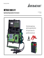
METRISO 5000 D-PI
Digital High-Voltage Insulation Test Instrument
Operating Instructions
Test instrument may
only be operated under
the supervision of a
qualified electrician!
3-349-210-03
8/6.13

2 GMC-I Messtechnik GmbH
12345
6
7
8
9 10
13
12
12
15
11
18
16
19
17
11
14

GMC-I Messtechnik GmbH 3
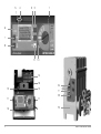
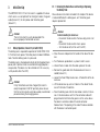
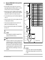
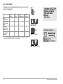
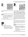
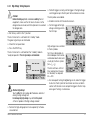
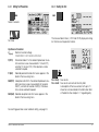
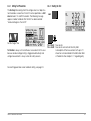
1 Function selector switch
Switch positions:
SETUP: General device settings
Print out measured values and reports
Select data memory function
OFF: Switches the test instrument off *
TEST: Select measuring and test parameters,
and execute measurements and tests
2 : Select main menus and submenus, and adjust values
3 : Select main menus and submenus, and adjust values
4 Socket connector for RS 232 interface
5LCD panel
6 Signal lamp for test passed (green) / test failed (red)
7 MENU: Key for selecting and querying menus for setting
parameters, for returning to the main menu and for
stopping the measuring process
8 i/STORE: Before performing a measurement:
Key for querying context sensitive help
After performing a measurement:
Key for saving measured values and parameters to memory
9 START: Key for starting the selected test
10 Signal lamp: “testing ...” (yellow)
11 Pushbuttons (left and right) for releasing the handle
12 Pushbuttons (left and right) for releasing the cover
13 Cover
14 SECUTEST PSI printer module
15 Handle and bar function as a tilt stand
* During battery operation: battery is disconnected
During mains operation: transformer is still connected to the mains
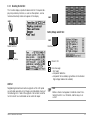
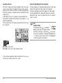
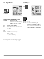
16 Inlet plug for supply power with fuse compartment
17 Connector jack for guard cable (feature G1)
18 Connection for automotive charging adapter J1
19 Device base
Outside: With uptake for measurement cable, test probes and alligator clips
Inside: Uptake for guard cable with test probe (feature G1),
battery compartment
Attention!
!
Connect 5 m long Leadex 5000 accessory extension
cable (feature H1) to + measurement cable only!
Note
Maximum rated voltage to earth is 1000 V~, even if perma-
nently connected measurement cables for 2 kV~ CAT II
are permissible.

4 GMC-I Messtechnik GmbH
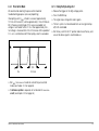
Retrofitting with a high-voltage module (feature B1 or B2) can only
be performed by GMC-I Service GmbH.
The high-voltage module is
then controlled by METRISO 5000 D-PI.
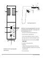
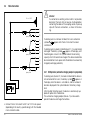
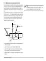
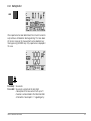
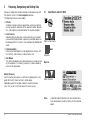
1 Inlet plug for high-voltage module supply power with fuse insert
2 Key switch for prevention of unauthorized start-up
3 Connection for external signal lamps (see chapter 3.2.3 on page 18)
4 High-voltage module ready for operation when signal lamp is lit up green
5 High-voltage module ready to switch on when signal lamp is lit up red
Caution, danger!
6 Permanently connected measurement cables
7Trigger (switch)
As opposed to the high-voltage pistol without switch, the high-voltage
switching pistol is identified with a red clamping ring on the connector cable
underneath the handle.
8 Recessed safety test probe
0
I
!
5
4
1
2
3
PROFITEST 204 HP/HV High-Voltage Module,
Connection Panel
6
8
7
High-Voltage Switching Pistol

GMC-I Messtechnik GmbH 5
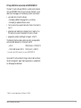
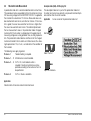
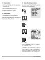
PC Program WinProfi for communication with METRISO 5000 D-PI
The free PC starter software WinProfi is used for communication
with your METRISO 5000 D-PI test instrument. WinProfi* is avail-
able on our homepage with the following content and functions:
• up-to-date test instrument software
– for loading a different language
for the user interface
– for loading an updated software version
• Transmission of measurement data from the test instrument to
the PC
• preparation and modification of templates for test reports at the
PC and transmission of the templates to the test instrument
• preparation, printout and filing of test reports at the PC
The following interface cables and/or converters are required for
communication between test instrument and PC:
– Z3241 RS232 (tester*) – RS232 (PC)
– RS232-USB Converter (Z501L) RS232 (tester*) – USB (PC)
* not possible via the RS232 terminal of a connected SECUTEST PSI
Up-to-date PC software (free of charge starter or demo software
for data management, report and list generation) is available from
our homepage for download.
* WinProfi is currently applicable up to Windows 7 (32 Bit)

Contents Page Contents Page
6 GMC-I Messtechnik GmbH
1 Applications ..................................................................................8
1.1 List of Available Features ...............................................................9
2 Safety Features and Precautions ................................................10
2.1 Checklist for High-Voltage Tests ....................................................11
2.2 Significance of Symbols .................................................................12
2.2.1 Symbols on the Device ..............................................................12
2.2.2 Symbols in the Operating Instructions .........................................12
2.2.3 Symbols in the User Interface ....................................................12
2.2.4 Symbols in the User Interface with Feature B1/B2 .......................13
2.3 Special Safety Precautions and Instructions
for Feature B1/B2 .........................................................................13
3 Initial Start-Up ............................................................................15
3.1 Battery Operation, Feature C1 (not with B1/B2) ...............................15
3.1.1 Removing the Device Base and Inserting or Replacing
the Battery Pack .......................................................................15
3.2 Initial Start-Up with Feature B1/B2 .................................................17
3.2.1 Retrofitting Feature B1/B2 .........................................................17
3.2.2 Key Switch (feature B1 or B2) ....................................................17
3.2.3 Indication of Operating States ....................................................18
3.3 Mounting the METRISO 5000 D-PI with Feature B1/B2 to the Trolley
(feature D1). .................................................................................19
3.4 Mains Connection .........................................................................20
3.4.1 DC Operation (automotive charging adapter in preparation) ..........20
3.5 User Interface ...............................................................................21
3.6 Help Functions ..............................................................................21
3.7 Setup ...........................................................................................22
3.7.1 Adjusting Contrast and LCD Illumination .....................................22
3.7.2 Setting Date and Time ...............................................................23
3.7.3 Beeper Settings .....................................................................24
3.7.4 Executing the Self-Test ..............................................................25
3.7.5 Downloading a Language or a Software Update .........................26
4 Performing Tests ........................................................................29
4.1 Insulation (resistance) Test ............................................................29
4.1.1 Setting Test Parameters ............................................................30
4.1.2 Starting the Test (U
NOM
, U
VAR
) ...................................................31
4.1.3 Starting the Test (U
STEP
) ............................................................31
4.1.4 Data logger function (min log)(as of firmware version AH) ............32
4.1.5 Measurements with the Guard Cable (feature G1) ......................33
4.2 High-Voltage Test with Feature B1/B2 ............................................34
4.2.1 Performance Test (preparation for testing) ..................................34
4.2.2 Setting Test Parameters for High-Voltage Testing .......................36
4.2.3 High-Voltage Testing Sequence .................................................37
4.2.4 Pulse Control Mode ...................................................................39
4.2.5 Ending the High-voltage Test .....................................................39
4.3 Polarization Index Measurement ...................................................40
4.3.1 Setting Test Parameters ............................................................41
4.3.2 Starting the Test .......................................................................41
4.4 Breakdown Voltage ......................................................................42
4.4.1 Setting Test Parameters ............................................................43
4.4.2 Starting the Test .......................................................................43
4.5 Capacitance Measurement and
Determination of Dielectric Discharge (optional)
................................. 44
4.5.1 Setting Test Parameters ............................................................44
4.5.2 Starting the Test .......................................................................45
4.6 Voltage Measurement (protection against residual voltage) ............46
4.6.1 Setting Test Parameters ............................................................47
4.6.2 Starting the Test .......................................................................47

GMC-I Messtechnik GmbH 7
Contents Page Contents Page
5 Processing, Reorganizing and Deleting Data ............................. 48
5.1 Select Device under Test (DUT) .................................................... 48
5.1.1 Entering Descriptions ............................................................... 49
5.1.2 Copying Descriptions ............................................................... 50
5.1.3 Deleting Descriptions ............................................................... 50
5.2 Processing Data (checking measured values) ................................ 50
5.3 Data Reorganization ...................................................................... 51
5.3.1 Deleting Already Printed Data ................................................... 51
5.3.2 Memory Test ........................................................................... 51
5.4 Clearing the Memory ................................................................... 52
6 Printing Test Results ................................................................. 53
7 Characteristic Values ................................................................. 54
8 Data Interfaces ........................................................................... 57
8.1 RS 232 Serial Interface ................................................................. 57
8.1.1 Software Analysis of Measurement Results ................................ 57
8.1.2 Interface Specification and Protocol ........................................... 57
8.1.3 Connector Pin Assignments ....................................................... 57
9 Displays and Error Messages – Causes – Remedies ................ 58
10 Maintenance .............................................................................. 61
10.1 Replacing the Mains Fuse ............................................................. 61
10.2 Testing of Rechargeable Batteries ................................................. 61
10.3 Housing and Test Probes .............................................................. 61
10.4 Measurement Cables .................................................................... 62
10.5 High-Voltage Module Test Cables (Feature B1/B2) .......................... 62
10.6 Replacing Bulbs in the External Signal Lamps (Feature F1) .............. 62
10.7 Software ...................................................................................... 62
10.8 Recalibration ................................................................................ 63
10.9 Device Return and Environmentally Compatible Disposal ................. 63
11 Appendix .................................................................................... 64
11.1 Glossary ..................................................................................... 64
11.2 Minimum Display Values in Consideration of
Measuring Error ........................................................................... 64
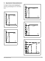
11.3
Voltage at Device Under Test During Insulation Resistance Test ...................65
11.4 Index ........................................................................................... 66
12 Repair and Replacement Parts Service,
Calibration Center and Rental Instrument Service .................................67
13 Product Support ......................................................................... 68

8 GMC-I Messtechnik GmbH
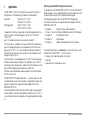
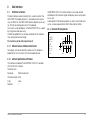
1 Applications
The METRISO 5000 D-PI insulation measuring instrument is in
compliance with the following standards and regulations:
Standard DIN EN 61557-1:2007
DIN EN 61557-2:2008
VDE regulation VDE 0413 Part 1:2007
VDE 0413 Part 2:2008
“Equipment for testing, measuring or monitoring protective mea-
sures in systems with line voltages of up to 1000 V AC and
1500 V DC,
part 2, insulation resistance measuring instruments”.
The instrument is suitable for the measurement of insulation resis-
tance at voltage-free devices and equipment with nominal volt-
ages of up to 1000 V. It is also suitable for the measurement of
insulation resistance with values of up to 1 T, and open-circuit
voltages of up to 5000 V.
The instrument is also equipped with a 1000 V measuring range
for direct and alternating voltages. This provides users with the
advantage of checking devices under test for the absence of volt-
age, and discharging capacitive devices under test.
All of the values required for approval reports can be measured
with this instrument.
The SECUTEST PSI module (feature I1) – a printer which can be
inserted into the cover which includes an integrated interface and
keypad – expands the range of possible applications for the
METRISO 5000 D-PI.
All measured data can be archived with the help of measurement
and test reports which can be printed out directly via a PC. This is
a very important feature, especially with regard to product reliabil-
ity.
Notes Regarding SECUTEST PSI Operating Instructions
In combination with the METRISO 5000 D-PI, the SECUTEST PSI
printer module is only used for printing out measured values and
for entering comments with the alphanumeric keypad.
The following chapters from the SECUTEST PSI operating
instructions are relevant as regards operation together with the
METRISO 5000 D-PI:
• Chapter 2 Safety Features and Precautions
• Chap. 3.1 and 3.2Installing the Batteries and the PSI Module
• Chapter 12 Characteristic Values
• Chapter 13 Maintenance
• Chapter 14 Repair and Replacement Parts Service
The following functions are not active, or only make sense in com-
bination with a SECUTEST test instrument:
• Display, print and store reports to memory
• Statistics
• Operation with a barcode scanner

GMC-I Messtechnik GmbH 9
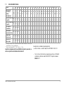
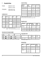
1.1 List of Available Features
1)
If the high-voltage module is purchased after the basic instrument, it can only be
retrofitted by our service department.
2)
Only for line voltage 207 V 253 V / 49 Hz 61 Hz
Specify the designation of the basic M5810 instrument in your order, as
well as any features which deviate from feature 0!
Example of a complete type designation
(= article number, = order code) for a METRISO 5000 D-PI:
– Test instrument for German speaking countries with DAkkS
calibration certificate and SECUTEST PSI printer module:
M5810 A01 I1
Features 0 0102030405070809101112131415172240414243
Country version
(user interface
language,
mains plug type)
A
D
GB in-
ter-
nati-
onal
GBR
UK
FRA
F
NLD
NL
ESP
E
FIN
FIN
SWE
S
ITA
I
NOR
N
BEL
B
DNK
DK
CZE
CZ
CHE
CH
KRO
HR
POL
PL
Port
P
Slo
SLO
Slow
SK
USA
USA
PROFITEST204HP/2.5kV
(not with C1)
B
1)
none
with
PROFITEST204HV/5.4kV
(not with C1)
B
1)
none
with
2)
Set of batteries
(not with B1, B2)
C none
with
“Guard 5000A”
measurement cable
G none
with
“LEADEX 5000”
extension cable
H none
with
SECUTEST PSI
printer module
I none
with

10 GMC-I Messtechnik GmbH
2 Safety Features and Precautions
The METRISO 5000 D-PI test instrument, and the
PROFITEST204HP/2.5kV and PROFITEST204HV/5.4kV high
voltage modules have been manufactured and tested in accor-
dance with the following safety regulations:
Standard DIN EN 61557-1:2007
DIN EN 61557-2:1998-05
IEC 61010-1:2004
EN 61010-1:2002
VDE regulation VDE 0413 Part 1:2007
VDE 0413 Part 2:1998-05
VDE 0411 Part 1:2002
If used for its intended purpose, safety of the user, the instrument
and the device under test is assured.
Read the operating instructions completely and carefully before using the
device, and follow all instructions included therein.
The operating instructions should be made available to all users.
Observe the following safety precautions:
• The instrument may only be connected to a 230 V or 120 V
electrical system (depending on the country-specific design)
which is protected with a fuse or circuit breaker with a maxi-
mum nominal current rating of 16 A.
• Be prepared for the occurrence of unexpected voltages at de-
vices under test (for example, capacitors may be dangerously
charged).
• Make sure that connector, measurement and test cables are
not damaged (i.e. broken insulation, kinks, interruptions etc.).
• The instrument may only be used indoors.
• Impulse withstand voltage of up to 2.5 kV may occur in
measurement category II systems with 230/400 V.
• If only the batteries are to be charged (instrument is ready for
operation in SETUP position), please ensure that the test in-
strument cannot be used by unauthorized personnel during
the charging process.
• Measurement may only be performed on voltage-free equip-
ment and devices.
• Measurements may not be performed under moist ambient
conditions, where condensation has occurred, or in explosive
atmospheres.
• Do not disconnect the measurement cables until the device
under test has been fully discharged.
• Observe accident prevention regulation BGV A3, “Electrical
Systems and Equipment”.
• Do not perform measurements alone: always have a second
person help if possible.
• Make sure that measurement cables are connected correctly.
• Do not touch the test probes at any point beyond the finger
guard.
The METRISO 5000 D-PI may not be used:
• If visible damage is apparent
• With damaged connector, measuring or test cables (test ca-
bles may not, under any circumstances, be mechanically dam-
aged or kinked, because impaired insulation characteristics
may otherwise result)
• If these no longer function flawlessly
• If the signal lamps on the PROFITEST204HP/2.5kV
(feature B1) and PROFITEST204HV/5.4kV (feature B2) high-
voltage modules are defective
In such cases, the devices must be removed from service and
secured against any possible inadvertent use.
Send the instrument to our Repair and Replacement Parts service
department in such cases (see chapter 12 on page 67).

GMC-I Messtechnik GmbH 11
Opening of Equipment / Repair
The equipment may be opened only by authorized service per-
sonnel to ensure the safe and correct operation of the equipment
and to keep the warranty valid. Even original spare parts may be
installed only by authorized service personnel.
In case the equipment was opened by unauthorized personnel,
no warranty regarding personal safety, measurement accuracy,
conformity with applicable safety measures or any consequential
damage is granted by the manufacturer.
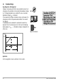
2.1 Checklist for High-Voltage Tests
Attention!
!
Measurements may not be performed under moist ambi-
ent conditions, where condensation has occurred or in
explosive atmospheres.
Personnel Safety
Ð Turn the machine under test off and lock it in the off position.
Ð Perform insulation resistance measurement.
Ð Make sure that the system is grounded.
Ð Secure the danger zone with barriers, closing even narrow en-
trance ways.
Ð Set up warning signs such that they are plainly visible.
Ð Set up warning lamps such that they are plainly visible.
Ð Attach the emergency stop button in a plainly visible fashion.
Ð Warn personnel working in the area of possible danger.
Ð Always turn the test instrument off with the key switch and re-
move the key before leaving the work area.
Safety Precautions for the Machine Under Test (recommended)
Ð
Review the circuit diagrams and make a note of all electrical circuits.
Ð Disconnect the neutral conductor from the mains.
Ð Short circuit each electrical circuit to itself.
Ð Disconnect control circuits with overvoltage arresters, if the ar-
resters would be triggered by utilized test voltage.
Ð Disconnect PELV circuits (no high-voltage testing is required
for these circuits).
Ð Test insulation at each circuit with 1000 V.
(If insulation resistance is OK at 1000 V, no failures should
occur during the high-voltage test.)
Ð Disconnect frequency converters.
Ð Caution in TN systems!
The protective conductor is connected to the neutral conduc-
tor in the junction box. High-voltage is thus applied between
the phase conductors and the neutral conductor.
The neutral conductor must be cut if necessary, because it is
not disconnected from the mains by means of fuses.
Setting Up the Test Instrument
High-Voltage Test
Ð
Test all circuits (conductors) against the protective conductor (all
switches in the mains circuit must be turned on, and testing must be
performed upstream and downstream from all relays and contactors).
Ð Remove all shorting devices after testing has been completed.
Testing Without Short-Circuiting
Ð Separately test all conductors from all circuits against the pro-
tective conductor (the machine could be damaged in the case
of arc-over).
Functions Test
Ð The machine must be tested for correct functioning after the
high-voltage test, especially as regards safety functions.

12 GMC-I Messtechnik GmbH
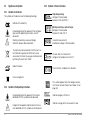
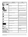
2.2 Significance of Symbols
2.2.1 Symbols on the Device
The symbols on the device have the following meanings:
Indicates EC conformity
Life endangering for the operator if the wiring dia-
gram and the operating instructions are not
observed!
Warning concerning a source of danger
(attention: observe documentation!)
This device may not be disposed of with the trash. Fur-
ther information regarding the WEEE mark can be
accessed on the Internet at www.gossenmetrawatt.com
by entering the search term ’WEEE’.
Report functions
Data management
2.2.2 Symbols in the Operating Instructions
Life endangering for the operator if instructions
identified with this symbol are not observed
Danger for the operator and the device if instruc-
tions identified with this symbol are not observed
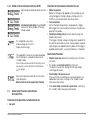
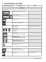
2.2.3 Symbols in the User Interface
High-voltage warning,
Voltage at the test probe
between 1000 and 5000 V
Warning concerning a source of danger,
Voltage at the test probe
between 25 and 1000 V
Insulation measurement:
interference voltage at the test probes
All-clear after an insulation test:
voltage at test probes less than 25 V
Timer function: symbolizes test duration
This symbol appears after the voltage measure-
ment value has been frozen (see chapter 4.6 on
page 46).
Indicates progress of the test.
Indicates storage of the measurement value.
!
!

GMC-I Messtechnik GmbH 13
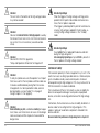
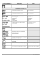
2.2.4 Symbols in the User Interface with Feature B1/B2
High-voltage module ready to be switched
on
Life endangering high voltage of up to 5.35 kV
is present at the test probes of the high-
voltage module.
Test completed successfully,
residual voltage less than 25 V
Display of phase angle
The specified limit value I
MAX
has been exceeded.
Current limiting has switched the device to the
“standby” mode.
The last voltage value measured before interrupting current
was exceeded, as well as interrupting current limit value
I
MAX
are displayed
Excessive temperature inside the test instrument
(high-voltage test)
Allow the device to cool for approximately 10 minutes.
2.3 Special Safety Precautions and Instructions
for Feature B1/B2
Precautions for the prevention of unauthorized start-up:
•Key switch
Precautions for the prevention of inadvertent start-up:
• Multiple key operation:
Before test voltage can be applied to the test probes by acti-
vating the trigger at the high-voltage switching pistol, the
START key must be pressed at the primary device.
• Two-hand operation:
Each of the high-voltage pistols is equipped with a trigger.
Both triggers must be activated simultaneously in order to ex-
pose both test probes.
• High-voltage switching pistol (pistol with yellow marking) with
double safety feature:
If the trigger at the high-voltage switching pistol is pulled to the
first point of mechanical resistance, the test probe is exposed.
High-voltage is not applied to the test probe until the trigger is
pulled beyond this point, assuming the device is switched on.
General Safety Precautions
• Integrated signal lamps indicate the switching status of the test
instrument.
• Test probes are electrically isolated from the mains:
This prevents current from flowing from the high-voltage
switching pistol to earth.
• Current limiting in the event of arc-over:
If the current limit value entered as a device parameter is ex-
ceeded due to arc-over, switching to the “standby” mode
takes place automatically.
•When mains voltage is restored after a power failure, switching to
the “standby” mode takes place automatically.
or
or

14 GMC-I Messtechnik GmbH
Attention!
!
The vent slots in the bottom of the high-voltage module
may not be covered!
Attention!
!
Observe the Rules for Electrical Testing Equipment issued by
the G
ERMAN TRADE ASSOCIATION FOR PRECISION ENGINEER-
ING AND ELECTRICAL ENGINEERING (see enclosed bro-
chure).
Attention!
!
Observe DIN VDE 0104 regulations:
“Setup and Operation of Electrical Test Equipment”
Attention!
!
If safety test probes are used, the operator must inspect
them to assure that the test probes and their cables are
in flawless condition before placing them into service.
All equipment must be inspected for visible, external
damage before use (see chapter 10.3 on page 61
through chapter 10.5 on page 62).
Attention!
!
Before initializing any tests, and before enabling test equip-
ment, make sure that all means of access to the danger
zone are closed, and that all persons have exited the
danger zone.
Attention High-Voltage!
When the trigger at the high-voltage switching pistol is
pulled to the first point of discernible mechanical resis-
tance, the test probe is exposed.
If the trigger is pulled beyond this point of mechanical re-
sistance, high-voltage is applied to the test probe, as-
suming the high-voltage module is in the “standby”
mode.
Attention High-Voltage!
Touch neither the test probe nor the device under test
during the high-voltage test!
Life endangering high-voltage of up to 5.35 kV is present at
the test probes of the high-voltage module!
Limitation of Liability
PCs located in proximity to the test equipment may “crash” in the
event of arc-over, resulting in possible data loss. All data and pro-
grams should be suitably saved, and computers shut down
before performing the high-voltage test. PCs may crash even if no
RS 232 connection has been established.
The manufacturer of the test instrument assumes no liability for
direct or consequential damages to computers or peripheral
devices, or for data loss during performance of the high-voltage
test.
Furthermore, the manufacturer assumes no liability for defects at
devices under test resulting from the high-voltage test. This
applies in particular to electronic components included in the
device under test.
Observe checklist for performance of high-voltage tests in chapter 2.1.

GMC-I Messtechnik GmbH 15
3 Initial Start-Up
The METRISO 5000 D-PI test instrument is supplied with a base
which serves as a compartment for storing test cables, the guard
cable (feature G1), the test probes and the battery pack
(feature C1).
Attention!
!
The test instrument may only be operated if the
base is properly attached and secured.
3.1 Battery Operation, Feature C1 (not with B1/B2)
The battery pack is required for operation of the METRISO 5000
D-PI without mains power. The battery back includes 8 NiMH bat-
teries. No other battery packs may be used.
The battery pack is charged automatically by the integrated mains
power pack. Optional use of an automotive charging adapter is
also possible. The device must be switched on in this case (any
switch position other than OFF).
Attention!
!
If only the batteries are to be charged (instrument is
ready for operation in SETUP position), please ensure
that the test instrument cannot be used by unauthorized
personnel during the charging process.
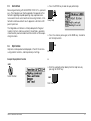
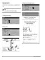
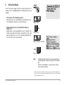
3.1.1 Removing the Device Base and Inserting or Replacing
the Battery Pack
Please observe instructions included in this chapter if the device
is to be retrofitted with a battery pack, or if the battery pack
requires replacement.
Attention!
!
Before dismantling the device base:
– Disconnect the device from the measuring circuit at all
poles.
– Disconnect the device from mains power.
– Turn the device off (set the switch to OFF).
Ð Close the cover and position the handle at the side of the de-
vice.
Ð Turn the device upside down, i.e. place it onto its cover.
Ð Unwind the test cables from the cable uptake at the side.
Ð Remove the guard cable from the device base if one is in-
cluded (feature G1).
Ð Loosen the three Phillips head screws at the bottom of the de-
vice base.
Ð Lift the device base up, and set it down at the side of the de-
vice with the feet at the bottom.
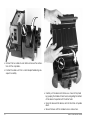
Ð Place the battery pack onto the two rubber cushions in the re-
cess in the device base such that the connector cable with
plug connector from the battery pack is on the same side as
the device’s connector cable with socket connector.
Double-check: The opening at the side of the base coincides
with the device’s connection panel.

16 GMC-I Messtechnik GmbH
Ð Connect the two cables to each other and secure the connec-
tion with the snap hooks.
Ð Position the cable such that is cannot be pinched during sub-
sequent assembly.
Ð Carefully set the device onto the base as shown in the photo
by grasping the handle with one hand, and guiding the bottom
of the device into position with the other hand.
Ð Grasp the base and the device, and turn the entire unit upside
down.
Ð Secure the base with the included screws and washers.

GMC-I Messtechnik GmbH 17
Attention!
!
Use only the screws furnished with the device together
with washers. Longer screws may reduce creepage dis-
tances or damage the device.
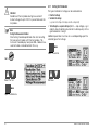
If a battery pack (feature C1) has been installed and the device is
not connected to the mains, the battery symbol appears at
the display when the device is switched on, and the number of
dark bars displayed in the symbol indicates the battery charge
level.
After installing the battery pack, the device is automatically sup-
plied with power from the batteries.
3.2 Initial Start-Up with Feature B1/B2
3.2.1 Retrofitting Feature B1/B2
Retrofitting with a high-voltage module (feature B1 or B2) can only
be performed by GMC-I Service GmbH.
The METRISO 5000 D-PI serves to determine the insulation value
in a non-destructive manner. If it is too low, it is possible to detect
the weak point with the high-voltage module (B1 or B2).
3.2.2 Key Switch (feature B1 or B2)
The key switch prevents unauthorized start-up of the high-voltage
module. Keep the key in a safe place which can only be accessed
by authorized personnel.
Torn the key to the “0” position and remove after each test has
been completed.
Note
When the key is removed or the high-voltage module
is turned off, the menu functions for the high-voltage
module cannot be accessed at the
METRISO 5000 D-PI!
Possible Danger of
Pinching!

18 GMC-I Messtechnik GmbH
3.2.3 Indication of Operating States
Signal Lamps at the High-Voltage Module
The signal lamps integrated into the high-voltage module indicate
two different operating states:
Green: Test instrument ready for use
• Key switch is in the “I” position (ON).
• Power supplies for signal and control circuits at the
high-voltage module are switched on.
• Test voltage supply circuits are still switched off, and are still
secured against inadvertent activation.
Attention!
!
All safety precautions required before entering the dan-
ger zone must now have been implemented, amongst
others: set up WS1 warning signs and ZS2 auxiliary
signs in accordance with DIN 40008, part 3.
Red: Instrument ready for operation, caution: danger!
• The menu for starting the voltage test has been opened, and
the START key has been activated.
• The power supply circuit for the safety test probe is still
switched off, assuming the trigger has not been pulled at the
high-voltage pistol.
• The test probes are secured against inadvertent contact, as-
suming the triggers at the high-voltage pistols have not been
pulled.
Attention!
!
All means of access to the danger zone must be closed
when the high-voltage module is in the “standby” mode!
The device must be sent to GMC-I Service GmbH in order to
replace lamps.
External Signal Lamps (feature F1)
The external signal lamps indicate the same operating states as
the signal lamps integrated into the high-voltage module. They
provide additional security at the test site, and must be plainly vis-
ible beyond the boundaries of the danger zone.
The external signal lamps can only be connected to the 12 V/5 W
output jack at the high-voltage module (feature B1 or B2).
Note
For reasons of safety, only Z504D signal lamps available
from GMC-I Messtechnik GmbH may be used.
Refer to chapter 10.7 on page 62 regarding lamp replacement

GMC-I Messtechnik GmbH 19
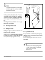
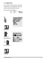
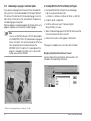
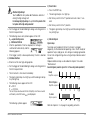
3.3 Mounting the METRISO 5000 D-PI with Feature B1/B2 to
the Trolley (feature D1).
Ð Set the complete unit consisting of test instrument and
high-voltage module onto the trolley’s platform (1) such that
the cover of the test instrument can still be opened.
Ð Secure the test instrument’s handle to the vertical supports
with the handle clamps (3). Loosen the screws in the handle
clamps (9) to this end with a 4 mm hollow hex wrench.
Ð Push the handle clamps (3) over the handle and retighten the
screws (9).
Ð Wind the two cables from the safety test probes onto the bot-
tom cable uptake (2 at bottom).
Ð Then wind the two cables from the test instrument’s test
probes onto the top cable uptake (2 at top).
Ð Secure the cables and the test probes with the included rub-
ber straps (12).
Attention!
!
Observe regulations for portable test equipment in ac-
cordance with DIN VDE 0104 (3.6).
Note
Wind the test cables from the safety test probes onto the
provided cable uptakes at the back of the trolley after
each use. Test cables may not, under any circumstances,
be mechanically stressed or kinked, because impaired
insulation characteristics may otherwise result. Do not
forget that externally caused damage is not always rec-
ognizable.
Attention!
!
Inspect the test cables for mechanical damage before
placing the high-voltage module into service each time it
is used.
10
11
8
2
3
2
5
6/7
1
4
9
Item Designation Qty. Order Number
1 Base 1 3-117-193-01
2 Cable uptake 2 3-326-653-01
3 Handle clamp 2 3-326-652-01
4 Cover 2 3-164-609-01
5 Wheel 2 3-419-038-01
6 Washer 4 3-740-013-01
7
Retaining ring
2 3-743-024-59
8 Screw 6 3-712-007-10
9 Hex nut 6 3-730-119-12
10 Screw 2 3-716-018-24
11 Trolley frame 1 3-121-111-01
12 Rubber strap 2 3-326-627-01
13
Protective cover
1 3-171-302-01
Caddy 204 Trolley

20 GMC-I Messtechnik GmbH
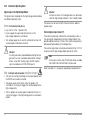
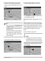
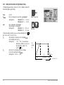
3.4 Mains Connection
Ð Connect the test instrument to 230 V or 120 V mains power
(depending on the country-specific design) with the included
mains connector cable.
Attention!
!
If a connection via earthing contact outlet is not possible,
disconnect the mains from all sources of voltage before
connecting the cables of the coupling socket via pick-up
clips with the mains connections, as shown in the draw-
ing.
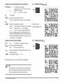
If a battery pack has not been installed, the mains connection
symbol appears after the test instrument has been
switched on.
If a battery pack has been installed (feature C1), it is automatically
recharged. The battery symbol appears at the display, and
the blinking bars shown in this symbol indicate the remaining
capacity which still needs to be charged. The device need not be
disconnected from mains power after the batteries have been fully
charged (overcharge protection).
3.4.1 DC Operation (automotive charging adapter in preparation)
If a battery pack (feature C1) has been installed and the device is
not connected to the mains, the battery symbol appears at
the display when the device is switched on, and the number of
dark bars displayed in the symbol indicates the battery charge
level.
After installing the battery pack, the device is automatically sup-
plied with power from the batteries.
The automotive charging adapter (feature J1) can be used to
operate the device and charge the batteries.
L1
N
green-yellow
green-yellow
PE
L1
L2
L3
N
PE
L1
L2
L3
N
green-yellow
U
L–N
= 230 V
Page is loading ...
Page is loading ...
Page is loading ...
Page is loading ...
Page is loading ...
Page is loading ...
Page is loading ...
Page is loading ...
Page is loading ...
Page is loading ...
Page is loading ...
Page is loading ...
Page is loading ...
Page is loading ...
Page is loading ...
Page is loading ...
Page is loading ...
Page is loading ...
Page is loading ...
Page is loading ...
Page is loading ...
Page is loading ...
Page is loading ...
Page is loading ...
Page is loading ...
Page is loading ...
Page is loading ...
Page is loading ...
Page is loading ...
Page is loading ...
Page is loading ...
Page is loading ...
Page is loading ...
Page is loading ...
Page is loading ...
Page is loading ...
Page is loading ...
Page is loading ...
Page is loading ...
Page is loading ...
Page is loading ...
Page is loading ...
Page is loading ...
Page is loading ...
Page is loading ...
Page is loading ...
Page is loading ...
Page is loading ...
-
 1
1
-
 2
2
-
 3
3
-
 4
4
-
 5
5
-
 6
6
-
 7
7
-
 8
8
-
 9
9
-
 10
10
-
 11
11
-
 12
12
-
 13
13
-
 14
14
-
 15
15
-
 16
16
-
 17
17
-
 18
18
-
 19
19
-
 20
20
-
 21
21
-
 22
22
-
 23
23
-
 24
24
-
 25
25
-
 26
26
-
 27
27
-
 28
28
-
 29
29
-
 30
30
-
 31
31
-
 32
32
-
 33
33
-
 34
34
-
 35
35
-
 36
36
-
 37
37
-
 38
38
-
 39
39
-
 40
40
-
 41
41
-
 42
42
-
 43
43
-
 44
44
-
 45
45
-
 46
46
-
 47
47
-
 48
48
-
 49
49
-
 50
50
-
 51
51
-
 52
52
-
 53
53
-
 54
54
-
 55
55
-
 56
56
-
 57
57
-
 58
58
-
 59
59
-
 60
60
-
 61
61
-
 62
62
-
 63
63
-
 64
64
-
 65
65
-
 66
66
-
 67
67
-
 68
68


Gossen MetraWatt METRISO 5000D-PI Operating instructions
- Category
- Measuring & layout tools
- Type
- Operating instructions
Ask a question and I''ll find the answer in the document
Finding information in a document is now easier with AI
Related papers
-
Gossen MetraWatt METRISO PRIME+ Operating instructions
-
Gossen MetraWatt METRAHIT 16I Product information
-
-
-
-
-
-
-
-
Other documents
-
Makita ML183 User manual
-
Megger S1-1052/2 User manual
-
-
Amprobe MEGATEST-5000 Megohmmeter User manual
-
KYORITSU 3551 Owner's manual
-
Fluke 1630-2 FC Earth Ground Clamp User manual
-
Sanwa MG5000 User manual
-
Fischer FERITSCOPE FMP30 User manual
-
Fluke 1550C FC 5 kV Digital Insulation Tester User manual
-
CHAUVIN ARNOUX C.A 6549 User manual