Page is loading ...

ACV International
1
Kompakt HRE eco
12 Solo
18 Solo
30 Solo
40 Solo
Installation instructions
Read these installation instructions carefully before installing and using the
appliance.
Keep these installation instructions with the appliance.
Always act in accordance with the instructions indicated.

ACV International 2
INDICE
1
SAFETY REGULATIONS 4
1.1 General ............................................................................................................................................................................................ 4
1.2 Central heating installation .............................................................................................................................................................. 4
1.3 Gas installation ................................................................................................................................................................................ 4
1.4 Electrical installation ........................................................................................................................................................................ 4
1.5 Drinking water installation (only in combination with external DHW tank) ....................................................................................... 4
1.6 Flue pipe and air supply................................................................................................................................................................... 4
2 Description of appliance 5
2.1 General ............................................................................................................................................................................................ 5
2.2 Operation ......................................................................................................................................................................................... 5
2.3 Operating modes ............................................................................................................................................................................. 5
2.4 PC Interface ..................................................................................................................................................................................... 7
2.5 Test program’s ................................................................................................................................................................................. 7
3 Principal components 8
4 Installation 9
4.1 Overall dimensions .......................................................................................................................................................................... 9
4.2 Installation location ........................................................................................................................................................................ 10
Installing the appliance ............................................................................................................................................................................... 11
5 Connection 12
5.1 Connecting CH installation ............................................................................................................................................................ 12
5.2 Connecting a DHW tank ................................................................................................................................................................ 13
5.3 Electrical connection ...................................................................................................................................................................... 14
5.4 Connect room thermostat .............................................................................................................................................................. 15
5.5 Gas connection .............................................................................................................................................................................. 16
5.6 Flue pipe and air supply................................................................................................................................................................. 17
5.7 Pipe lengths ................................................................................................................................................................................... 18
5.8 Balanced flue assemblies .............................................................................................................................................................. 20
5.9 Roof outlet Common Flue System ................................................................................................................................................. 30
6 COMMISIONING the appliance 32
6.1 Filling and venting the appliance and the installation .................................................................................................................... 32
6.2 Commissioning the appliance ........................................................................................................................................................ 33
6.3 Shutting down ................................................................................................................................................................................ 34
7 Setting and adjustment 35
7.1 Directly via the operating panel ..................................................................................................................................................... 35
7.2 Settting via the service code .......................................................................................................................................................... 36
7.3 Parameters .................................................................................................................................................................................... 36
7.4 Activating and de-activating DHW comfort .................................................................................................................................... 37
7.5 Setting maximum CH power .......................................................................................................................................................... 38
7.6 Setting pump setting ...................................................................................................................................................................... 38
7.7 Weather–dependent adjustment ................................................................................................................................................... 39
7.8 Conversion to different gas type .................................................................................................................................................... 40
7.9 Gas-Air ratio control. ...................................................................................................................................................................... 41
7.10 Checking the gas air ratio control .................................................................................................................................................. 42
8 FAults 46
8.1 Fault codes .................................................................................................................................................................................... 46
8.2 Other faults .................................................................................................................................................................................... 46
9 Maintenance 49
10 Technical specifications 51
10.1 NTC resistances ............................................................................................................................................................................ 51
10.2 Product Fiche according to CELEX-32013R0811, ANNEX iV ....................................................................................................... 52
10.3 Electrical diagram Kompakt HRE eco Solo ................................................................................................................................. 53
11 Warranty provisions 54
12 CE- Declaration 54

ACV International
3
© 2016 ACV International
All rights reserved.
The information provided applies to the standard version of the product. ACV International cannot
therefore be held liable for any loss or damage arising from product specifications deviating from the
standard version. The available information has been compiled with all possible care, but ACV
International cannot be held liable for any errors in the information or for the consequences thereof.
ACV International cannot be held liable for any loss or damage arising from work performed by third
parties.
Subject to change
This manual
This manual will enable you to assemble, install and maintain the appliance safely.
Follow the instructions meticulously.
In case of doubt contact the manufacturer.
Keep these installation instructions with the appliance.
Abbreviations and descriptions used
Description Reffered to as
High efficiency HE
ACV Kombi Kompakt HRE wall mounted gas fired
boiler
Appliance
Appliance plus pipework for central heating CH installation
Pictograms
The following pictograms are used in this manual:
CAUTION
Procedures which – if they are not performed with the
necessary caution – can result in damage to the product, the
surrounding area or the environment, or in physical injury.
Service and technical support
For information about specific adjustments, installation, maintenance and repair work,
please contact:
ACV International
Oude Vijverweg 6
B-1653 Dworp
www.ACV.com
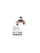
Product identification
You will find the appliance data on the data plate on the underside of the appliance.
A. Appliance type
B. Hot water power rating (kW)
C. Power rating, upper and lower value (kW)
D. Rated power (kW)
E. Gas category
F. Gas connection pressure (mbar)
G. Gas type set
H. Pin
I. Appliance category
J. Maximum CH pressure (bar)
K. Maximum CH water temperature (°C)
L. n/a
M. Electrical connection
N. NOx number
O. Serial number
P. Year of manufacture

ACV International 4
1 SAFETY REGULATIONS
The manufacturer ACV International accepts no liability whatsoever for damage or
injury caused by failure to adhere (strictly) to the safety regulations and instructions, or
carelessness during installation of the Ïntergas Kombi Kompakt High Efficiency wall
mounted gas fired boiler and any associated accessories.
1.1 General
The system as awhole must satisfy the applicable safety and other regulations, as
indicated in:
•
These installation instructions.
•
NEN 1087: Ventilation in buildings – Determination methods for new estate
•
NEN 3215: Drainage systems inside buildings.
•
The Building Decree.
•
Local regulations of municipal authority, fire service and public utilities.
1.2 Central heating installation
The entire installation must comply with the applicable safety and other regulations, as
indicated in:
•
NEN 3028: Requirements for fuel combustion installations.
1.3 Gas installation
The entire installation must comply with the applicable safety and other regulations, as
indicated in:
•
NEN 1078 (2004): Supply for gas with an operating pressure up to and including 500
mbar – performance requirements- new estate
•
NPR 1088: Ventilation in dwellings and residential buildings.
•
NPR 3378: Guidelines for gas installations.
•
NEN 2920: Requirements for domestic gasconsuming installations and . . . on
commercial butane, commercial propane en butane/propane mixtures.
1.4 Electrical installation
The entire installation must comply with the applicable safety and other regulations, as
indicated in:
•
NEN 1010: Safety requirements for low-voltage installations
1.5 Drinking water installation (only in combination with external
DHW tank)
•
NEN 1006: General requirements for water supply installations.
1.6 Flue pipe and air supply
The flue pipe and air supply installation must comply with:
•
NEN 1078 (2004): Supply for gas with an operating pressure up to and including 500
mbar – performance requirements- new estate
•
NEN 2757: Air supply and smoke outlet of incineration furnaces in buildings –
determination methodes.
•
NPR 3378: Guidelines for gas installations.

ACV International
5
2 DESCRIPTION OF APPLIANCE
2.1 General
The ACV Kombi Kompakt HRE wall mounted, gas fired boiler is a closed appliance.
The appliance is intended to deliver heat to the water in a CH system and the DHW
installation.
The air supply and combustion gas flue can be connected to the appliance by means
of two separate pipes. A concentric connection can be supplied if requested. The
appliance has been inspected in combination with the ACV “combi duct”, but it can
also be connected to combi ducts that comply with the universal requirements for
combi ducts and which carry a ‘Gaskeur’(Dutch gas certification).
Depending on preference, the appliance may be connected to a mounting bracket, a
frame with top connection and various connection sets. These are supplied separately.
The ACV Kombi Kompakt HRE wall mounted gas fired boilers carry the CE label, IP
44 rating and the ‘Gaskeur’ (Dutch gas certification) labels HR & SV.
The appliance is supplied as standard for natural gas (G20). On request a conversion
set for propane (G31) can be delivered.
2.2 Operation
The ACV Kombi Kompakt HRE wall mounted, gas fired boiler is a modulating high
efficiency boiler. This means that the power is adjusted in line with the desired heat
requirement.
The aluminium heat exchanger comprises a copper circuit.
By using a devider valve and a sensor the ACV Kompakt Solo can be connected to
an external DHW tank. The internal boiler controller regulates the DHW demand and
assures that DHW supply takes priority over the heating.
The appliance has been provided with an electronic burner controller that controls the
fan with the heat demand from either heating system or external DHW tank, opens the
gas valve, ignites the burner and continuously monitors the flame and controls it
dependent on the power required.
.
2.3 Operating modes
A code on the service display of the operating panel indicates the appliance’s
operating mode.
- Off
The appliance is out of operation but is supplied with electrical power. No response
occurs to calls for DHW or CH. The appliance frost protection is active. This means
that the pump operates and the exchanger is heated up if the temperature of the water
present in it falls too far.
If the frost protection is actuated, code
7 is displayed (heating exchanger).
In this operating mode the pressure in the CH installation (in Bar) can also be read on
the temperature display.
Waiting mode
The LED at the button is lit and possibly one of the LEDs for the DHW comfort
function. The appliance is ready to respond to a request for CH of DHW.
0 Running on of CH
After the end of CH operation the pump continues to run. The running on time is
factory set at he value in accordance with section 7.3 , page:36. This setting can be
changed.
In addition, the pump runs automatically for 10 seconds once every 24 hours in order
to prevent seizing. This automatic switching on of the pump occurs at het time of the
last call for heat. To change the time, the room thermostat setting should be increased
briefly at the desired time.

ACV International 6
1 Desired temperature reached
The burner manager can temporarily block the request for heat. The burner is then
stopped. Blocking occurs because the requested temperature has been reached.
When the temperature has fallen sufficiently the blocking is cancelled.
2 Self-test
The connected sensors are checked regularly by the burner manager. During the
check the manager does not perform any other tasks.
3 Ventilation
When the appliance is started the fan is first brought to starting speed. When the
starting speed has been reached the burner is lit. Code
3 is also visible when post-
ventilation is taking place after the burner has stopped.
4 Ignition
When the fan has reached the starting speed, the burner is ignited by means of
electrical sparks. During ignition the code
4 is visible. If the burner does not ignite,
a new ignition attempt occurs after approximately 15 seconds. If after 4 ignition
attempts the burner is not yet burning, the burner manager goes into fault mode.
(See section 8.2.1).
5 CH operation
An of/off thermostat, an OpenTherm thermostat, an external sensor or a combination
of the latter can be connected to the burner manager. (See section 10.2)
When a request for heat is received from a thermostat, the fan is started (code
3 ),
followed by ignition (code 4 ) and CH operating mode (code 5 ).
During CH operation the fan speed and hence the appliance power are controlled by
the burner manager so that the CH water temperature reaches the desired CH
supply temperature.
If an on/off thermostat is connected, this is the CH supply temperature set on the
display. In the case of an OpenTherm thermostat the desired CH supply temperature
is determined by the thermostat. In the case of an external sensor the desired CH
suppply temperature is determined by the heating line programmed in the burner
manager. For the latter two, however, the maximum is the temperature set on the
display.
The CH operation the requested CH supply temperature is indicated on the operating
panel.
The CH supply temperature can be set between 30°C and 90°C. (See section 7.1).
The actual CH supply temperature can be read by pressing the service button during
CH operation.
When the DHW comfort function is switched on (See code
7 ) any OpenTherm
request for heat of less than 40°C is ingored.
The resistance R may be removed if the room thermostat does not need anticipation
current. (See section 10.2)
6 DHW operation
The hot water supply takes priority over the heating. When the sensor in the DHW
tank measures a temperature 5 °C below the setting, an eventual CH demand will be
stopped, the devider valve will switch and the boiler will heat up the DHW tank until
the demanded temperature has been reached. During this process the display shows
code
6
When a thermostat is used instead of a sensor the DHW heat demand starts when
the thermostat opens en stops when the thermostat clothes.
During DHW operation the fan speed, and hence the power of the appliance, are
controlled by the burner manager so that the DHW water temperature reaches the
DHW temperature setting.
The water temperature can be set between 40°C and 65°C (See section 7.1) and is
displayed on the operating panel during DHW operation.
The actual DHW temperature can be read by pressing the service button during
DHW operation.

ACV International
7
2.4 PC Interface
The burner manager is equipped with an interface for a PC, which can be connected by
means of a special cable and associated software. This facility allows the behaviour of
the burner manager , the appliance and the heating installation to be monitored over a
longer period.
2.5 Test program’s
The burner manager has a facility for placing the appliance in test mode.
Activation of a test program will result in the appliance starting operation at a fixed fan
speed, without the control functions being actuated.
The safety functions do remain active.
The test program is ended by pressing the
and simultaneously.
Test programs
Program description Button
combinations
Display reading
Burner on at minimum CH power and “L”
Burner on with maximum CH power
setting (See section 7.3, parameter 3)
and (1x) “h”
Burner on with maximum DHW power
(See section 7.3, parameter 4)
and (2x) "H"
Switch off test program and
Actuele
bedrijfssituatie
Addition readings :
During test mode the following data can be read :
•
By pressing the button continuesly in the display the CH water pressure is shown.
•
By pressing the button continuesly in the display the ionisation current is shown.
2.5.1 Frost protection
•
To prevent freezing of the appliance it is equipped with appliance
frost protection. If the heat exchanger temperature falls to low, the
burner swiches on and the pump runs until the heat exchanger
temperature is sufficient. When the appliance frost protection is
actuated code
7 ‘ is displayed (pre heating exchanger).
•
If the installation (or a part of it) can freeze, an (external) frost
thermostat must be fitted to the return line at the coldest location.
This must be connected in accordance with the wiring diagram.
(See section 10.2.)
Note
If the appliance is out of operation (
-
on the service display) the appliance frost
protection is active. However, a request for heat from an (external) frost thermostat will not
be responded to.

ACV International 8
3 PRINCIPAL COMPONENTS
P
R
S
A. CH pump K. Air inlet
B. Gas valve L Flue pipe adapter
C. Burner manager M. Connection block / terminal strip X4
D. Supply sensor S1 N. Condensate drain pan
E. Return sensor S2 O. Siphon
F. Fan P. Position data plate
G. CH pressure sensor Q. Heat exchanger
H. Mains lead 230 V AC with grounded plug R. Operating panel and read-out
I. Manual air bleed S. Ignition/ionisation pin
J. Inspection glass

ACV International
9
4 INSTALLATION
4.1 Overall dimensions
Appliance with connections downwards:
Appliance + mounting bracket
A =
Supply CH
Ø22
B =
Return CH
Ø22
C =
Gas
½” (F)
F =
Condensate drain
Ø25 (flexible)
h =
517
HRE eco
12 and
18 Solo
637
HRE
eco
30
and 40 Solo
H=
590
HRE
eco
Solo
12 and
18
710
HRE
eco
30
an
d 40 Solo
Y =
Air supply
Ø80 (*)
Z1 =
Flue pipe
Ø80 (*
)
Z2 =
Flue pipe / air
supply
Concentric
Ø60/100
(stan
dard)
or Ø80/125 (*)
(*) After changing the flue adapter
Appliance + mounting bracket + complete bottom
connection set
A =
Supply CH
Ø2
2 (compression)
B =
Return CH
Ø22 (compression)
C =
Gas
Ø15 (compression)
F =
Condensate drain
Ø25 (flexibel)
Y =
Air supply
Ø80 (*)
Z1 =
Flue pipe
Ø80 (*
)
Z2 =
Flue pipe / air
supply
Concentric Ø60/100
(stan
dard)
or Ø80/125 (*)
(*) After changing
the flue adapter

ACV International 10
4.2 Installation location
The appliance should be fitted to a wall that has sufficient bearing strength.
In case of light wall structures the possibility exitsts that resonance noise may occur.
There must be an earthed wall socket within 1 m of the appliance.
If the appliance is installed as an open appliance, the installation location should be
equipped with the necessary openings for the combustion air supply. (See section
5.6.2)
To prevent freezing of the condensate drain pipe, the appliance must be installed in a
frost –free room.
4.2.1 Installing in a kitchen cupboard
The appliance can be installed between two kitchen cabinets or in a cabinet.
Ensure sufficient ventilation at top and bottom. If the appliance is installed in a
cabinet, ventilation openings of at least 50 cm
2
must be created.
4.2.2 Removing cover plate and front panel
For various work on the appliance the cover plate and front panel should be removed
from the appliance. Proceed as follows:
•
If cover plate (A), is used, remove to the front.
•
Unscrew the two screws (1) behind the appliance display cover.
•
Pull the bottom of the front panel (2) forwards.

ACV International
11
Installing the appliance
1. Unpack the appliance.
2. Check the contents of the packaging; the consist of:
• Appliance (A)
• Suspension strip (B)
• Siphon (C)
• Installation instructions
• Operating instructions
• Warranty card
3. Check the appliance for possible damage: report damage immediately to the
supplier.
4. Check whether the compression rings are sitting squarely in the mounting
bracket couplings.
5. Fit the appliance, sliding it downwards over the suspension strip. Ensure at the
same time that the pipes slide into the compression fittings.
6. Tighten the compression fittings on the mounting bracket. The nipples must not
be allowed to turn!
7. Open the display cover and unscrew the two screws behind. Then remove the
front panel.
8. Fit the flexible tube to the siphon outlet.
9. Fill the siphon with water and slide it as far as possible upwards on to the
condensate drain connector (C) below the appliance.
10. Connect the flexible tube (A) from the siphon (where applicable together with the
overflow pipe from the inlet assembly and the pressure relief valve) to the drain
via an open connection (B).
11. Fit the air supply and the combustion gas flue. (See section 5.6)
12. Place the front cover and tighten the two screws (hand tight), close the display
cover.
C Clo
IMPORTANT
The Kompakt HRE eco 40 Solo is only to be used in
combination with the accompanying siphon .
Make sure that, when replacing the siphon the correct
version is ordered (art. nr. 91844787)
4.2.3 Fit the cover plate
Hang the flanged upper edge of the cover plate on the washers under the base of the
appliance and slide the cover plate as far as possible towards the rear.

ACV International 12
5 CONNECTION
5.1 Connecting CH installation
1. Flush the CH system thoroughly to clean.
2. Fit the supply pipe (B) and the return pipe (A) to the mounting bracket.
3. All pipes must be fitted unstressed in order to prevent the pipes from ticking.
4. Existing connections must not be twisted, in order to avoid leakages.
The CH system should be equipped with:
•
A filling/draining tap (A) in the return pipe immediately below the appliance.
•
A drain tap at the lowest point(s) of the installation.
•
A 3 bar pressure relief valve (B) in the supply pipe at a maximum distance of 500
mm from the appliance.
There must be no valve or constriction between the appliance and the overflow
valve.
•
An expansion vessel in the return pipe.
•
A check valve, if pipes run upwards at a short distance from the appliance. This
avoids the occurrence of thermosiphon effect during DHW operation mode.
5.1.1 Thermostatic radiator valves
If all radiators are equipped with thermostatic or regular radiator valves, a bypass must
be fitted in order to guarantee minimum water circulation. The bypass must be at a
distance of at least 6 m from the appliance in order to prevent overheating of the
appliance.
Appliance with zone regulation.
If there is, next to the CH system another heating source (as for example a stove or a
fireplace) in the living room often the problem occurs that the other rooms cool down.
This can be solved by splitting up the CH system into two separate zones.
The zone regulation can only be used if there is no external DHW tank present (in case
of a system boiler)
Schedule zone-regulation
A. Appliance
B. Electrical Shut-off valve 230 V ~
C. Radiators
T1. Room thermostat zone 1
T2. Room thermostat zone 2
Z1. Zone 1
Z2. Zone 2
Operating principle
The zone regulation contains 2 room thermostats and a shut off valve. When the room
thermostat of zone 2 generates a heat demand, the shut off valve opens and the
complete CH system heats up (zone 1 and 2). When the heat demand of zone 2 is not
or no longer present, room thermostat 1 controls the room temperature in zone 1.
Installation
5. Place the shut-off valve into the heating system according to the schedule.
6. Connect the room thermostat of zone 1 on to connector X4 – 6/7.
7. Connect the room thermostat of zone 1 on to connector X4 – 11/12.
8. Modify parameter A in the parameter list. (See § 7.3)
INote : The room thermostat for zone 1 must be an on/off type. The room thermostat for
zone 2 an be either on/off or “Open Therm”.

ACV International
13
5.2 Connecting a DHW tank
For connecting the Kompakt Solo HR on an indirect heated DHW tank the following
parts can be ordered:
•
Sensor set for DHW tank (art. nr. 065.117)
•
Devider valve set (art. nr. 092647).
Connect the DHW tank and the devider valve on in accordance with the schedule.
Remove the link between 9 and 10 of connector X4.
Connect cable of the devider valve to connector X2 and the DHW tank sensor to
connector X4 (see schedule § 10.2)
Aansluitschema indirect gestookte boiler
C Boiler
D DHW tank
E Central heating installation
F Exp. vessel
G Safety valve
H Divider valve
Remark
When using a DHW tank thermostat instead of a sensor heating up the tank will start
when the thermostat is open and stop with the thermostat closes again.

ACV International 14
5.3 Electrical connection
CAUTION
An earthed wall socket must be located no more than 1 metre
from the appliance.
The wall socket must be easily accessible.
For installation in damp rooms a fixed connection is
obligatory.
When workin on the ectrical circuit always remove the plug
from the wall socket
If the mains lead has to be replaced, this should be carried out
by the manufacturer
1. Slide the cover plate (A) (if present) to the front to remove.
2. Unscrew screw (A) to gain access to the burner manager (B).
3. Pull the burner manager unit forwards; the burner manager will tip downwards
to provide access.
4. Consult sections 5.3.1 and 10.2 for the making the connections.
5. After making the desired connections plug the appliance into an earthed wall
socket.
5.3.1 Electrical connections
Temperature control Connector X4 Notes
Room thermostat 6 - 7 On/Off
Modulating thermostat with
comfort function in use
11 - 12 6 – 7 open
Outside temperature sensor 8 - 9 -
External DHW disable- or
MIT switch
9 - 10 Boiler NTC or thermostat.
Note: Remove link 9-10.
Frost protection thermostat 6 - 7 Parallel to room
thermostat

ACV International
15
5.4 Connect room thermostat
5.4.1 Room thermostat on/off
1. Connect the room thermostat (see par. 10.1).
2. If necessary, set the feedback resistance of the room thermostat to 0.1 A. If unsure,
measure the electrical current and set it accordingly.
The maximum resistance of the thermostat pipe and the room thermostat amounts
to a total of 15 Ohm.
5.4.2 Modulating thermostat, Open Therm
The unit is suitable for connecting a modulating room thermostat, in accordance with
the OpenTherm communication protocol.
The most important function of the modulating room thermostat is to calculate the input
temperature at a required room temperature, in order to make optimal use of the
modulating. At every heating request, the required input temperature is shown on the
display of the unit.
Connect the modulating thermostat (see par.10.1).
If you want to use the tap water on/off switch function of the OpenTherm thermostat, the
tap water comfort function must be set to eco or on.
For more information, consult the manual of the room thermostat.
5.4.3 Modulating room thermostat, wireless
The ACV HRE boiler is suitable to communicate wirelessly without sending/receiving
module with the Honeywell room thermostats T87RF1003 Round RF, DTS92 and
CMS927. The CH boiler and the room thermostat must be appointed to each other:
•
Press the reset button of the unit for approximately 5 seconds in order to get to the
RF-
room thermostat menu.
• One of the following codes will be shown on the display of the unit:
1. rF and L /
-
: the display above the button shows an L alternated by a
–
red led : flashing
The CH boiler has not been appointed. A unit in this operating status, can be
linked by using the method of the appropriate room thermostat.
The method of appointment depends on the type of room thermostat and is
described in the installation and operating instructions of the wireless room
thermostat.
2. rF and L / 1 : the display above the
button shows an L alternated by a 1
red led : off
The CH boiler has already been appointed. There is already an existing link
with an RF room thermostat. In order to allow a new link to be made, the
existing link will have to be removed.
See: Undo the appointment of an RF room thermostat to the CH boiler.
• Press the reset
button to leave the RF room thermostat menu or wait for 1 minute.
Testing the connection between the unit and the RF room thermostat
1. Press the reset button of the unit for approximately 5 seconds to access
the RF room thermostat menu of the boiler controller.
2. Press the service button 1x. On the display above the button, a
t
will
be shown.
3. Set the room thermostat to the test mode (see the installation and operating
instructions of the room thermostat).
4. The red led above the reset
button will flash if the appointment has been
carried out correctly.
5. Press the reset
button of the unit to exit the RF room thermostat menu of
the boiler controller. You will automatically exit the test mode 1 minute after
the last test message of the RF room thermostat has been received.

ACV International 16
Undo the appointment of an RF room thermostat to the CH boiler.
• Press the reset
button of the unit for approximately 5 seconds to
access the RF room thermostat menu of the CH boiler.
• Press the service
button 2x. On the display above the button, a
C
will be shown.
• Press the reset
button of the unit again to remove the existing
appointments. The display of the unit will show rF again, with a flashing
L /
-
. If required, an RF room thermostat can be appointed to the unit
again.
• Press the reset
button of the unit to leave the RF room thermostat
menu or wait for 1 minute.
5.4.4 Outdoor temperature sensor
The unit is provided with a connection for an outdoor temperature sensor. The
outdoor temperature sensor should be used in combination with an on/off room
thermostat.
In principle, any on/off room thermostat can be combined with an outdoor sensor.
Upon request of the room thermostat, the boiler will provide heat until the maximum
set temperature in the boiler has been reached. This maximum set temperature is
automatically regulated via the outdoor sensor, in accordance with the set fuel line in
the boiler.
Connect the room outdoor sensor (see par. 10.1).
For the fuel line setting, see the weather dependent regulation (see par. Fout!
Verwijzingsbron niet gevonden.).
5.5 Gas connection
1. Fit a gas tap (A) between the gas supply and the appliance.
2. Fit the connection from the gas tap preferably directly into the ½”connection at
the mounting braket.
3. Install a gas filter mesh in the connection for the appliance if the gas may be
contaminated.
4. Connect the appliance to the gas supply.
5. Check the gas carrying parts for leakage at a maximum pressure of 500
mmH
2
O

ACV International
17
5.6 Flue pipe and air supply
•
The boiler is equiped with an adapter suitable to be connected to a concentric
flue system with the dimensions 60/100
•
The flue systems needs to be correctly connected into the adapter . The internal
seals in the adapter assure the tightness of the system.
•
By replacing the concentric adapter 60/100 by a 80/125 version the boiler can be
connected to concentric flue system with the dimensions 80/125.
•
By replacing the concentric adapter 60/100 by a single pipe 80 mm adapter and
removing the plastic cap from the air inlet connetion the boiler can be connected
to a twin pipe 80/80 flue system.
5.6.1 Draught, materials and insulation
Pipe Diameter Material
Air supply ø 80 mm As per the local fire service and/or power
company regulations.
‘Spiralotube’, single-walled aluminium,
galvanised sheet steel, stainless steel or plastic.
Possibly insulated with 10 mm vapour-tight
insulation material or plastic.
Combustion
gas flue
ø 80 mm As per table 8 of NEN 1078 (1987).
Insulation - 10 mm vapour-tight insulation material in case
of possibility of condensation on the outside as
a result of a low wall temperature and a high
room temperature with high relative humidity.
5.6.2 Open appliance connection
IMPORTANT
Make sure the boiler room complies to the regulatory
requirements for connecting to a flue system in accordance to
B23 or B33.
When connection the boiler to a flue system in accordance to
B23 or B33 the electrical protection class is IP20
1. Fit the pipe for the combustion gas flue into the flue outlet. The integral sealing
ring ensures an airtight connection.
5.6.3 Closed appliance connections
Two-pipe connection
1. Fit the pipes for the air supply and combustion gas flue into the appliance inlet
and outlet. The integral sealing rings ensure an airtight connection.
Concentric connection
With the concentric adapter set the standard two-pipe connection can be changed to
a concentric connection (80/125 or 60/100).
1. Fit the concentric pipe for the air supply and combustion gas flue into the
adapter. The integral sealing rings ensure an airtight connection.

ACV International 18
C13
C13
C33
C33
C33
5.7 Pipe lengths
As the resistance of the flue pipe and air supply pipe increases the appliance power will
decline. The maximum permitted reduction in power is 5 %.
The resistance of the air supply pipe and combustion gas flue depends on the length,
the diameter and all components of the pipe system. The total permitted pipe length of
the air supply and the combustion gas flue is indicated for each appliance category.
5.7.1 Pipe lengths using a concentric flue system
Concentrisc 60/100
C13 C33
Kompakt HRE eco 12 Solo 10 m 11 m
Kompakt HRE eco 18 Solo 10 m 11 m
Kompakt HRE eco 30 Solo 10 m 10 m
Kompakt HRE eco 40 Solo 10 m 10 m
Concentrisc 80/125
C13 C33 C93
Kompakt HRE eco 12 Solo 29 m 29 m
See §.5.8.8
Kompakt HRE eco 18 Solo 29 m 29 m
Kompakt HRE eco 30 Solo 29 m 29 m
Kompakt HRE eco 40 Solo 29 m 29 m
Vervangende lengten
Elbow 90° R/D=1 2 m
Elbow 45° R/D=1 1 m
Knee 90° R/D=0,5 4 m
Knee 45° R/D=0,5 2 m
Assembly:
For all concentric flue systems the following has to be considered:
1. Fit the concentric flue pipe into the adapter on the boiler
2. Connect all flue pipes to begin at the boiler and work towards the wall or roof
terminal. Make sure the connection is air tight.
3. A non vertical flue system must be connected with a minimum fall of 5mm/m
toward the boiler. If the outer pipe has a folded seam this needs to be
installed upwards.
Important: A wall terminal must be installed levelled

ACV International
19
5.7.2 Equivalent lengths
Bend 90° R/D=1 2 m
Bend 45° R/D=1 1 m
Elbow 90° R/D=0,5 4 m
Elbow 45° R/D=0,5 2 m
In the case of larger or smaller pipe diameters the permissible pipe length is greater or
smaller respectively.
In the case of smaller diameters the following applies:
Ø70: 0,59x the permissible pipe length for ø80
Ø60: 0,32x the permissible pipe length for ø80
Ø50: 0,15x the permissible pipe length for ø80
Contact the manufacturer for check calculations for the resistance of the air supply and
combustion gas flue pipe and the wall temperature at the end of the combustion gas
flue pipe.
5.7.3 Sample calculation
Pipe Pipe lengths Total pipe length
Flue pipe L1 + L2 + L3 + 2x2 m 13 m
Air supply L4 + L5 + L6 + 2x2m 12 m
Note
•
The total pipe length is:
Sum of the straight pipe lengths + sum of the equivalent pipe lengths of
bends/elbows.
•
Permissible length of air supply pipe and flue outlet pipe totals 85 m, excluding the
lenght of the combi duct or the dual-pipe duct.

ACV International 20
5.8 Balanced flue assemblies
Assembly general:
The assembly described below applies to all flue systems:
1. Slide the combustion gas flue pipe into the appliance flue outlet.
2. Slide the combustion gas flue pipes into each other.
Working from the appliance each pipe must be pushed into the previous pipe
3. Fit a non-vertical combustion gas flue pipe with a fall towards the appliance of minimal 5mm per metre
4. Fit flanged seams oriented upwards in a horizontal section.
5. Seal non-gastight connections with heat-and moisture-resistant aluminium tape.
Assemble all air supply pipes as indicates below:
1. Slide the air supply pipe into the appliance inlet.
2. Seal non-airtight connections with moisture-resistant tape.
3. Fit insulation if necessary.
Materials to be used:
Appliance
category
Materials Supplier
C13 Duct ACV
Other parts Gastec QA or ACV
C33 Duct ACV
Duct in the case of Prefab Gastec QA, ACV or third
parties
Other parts
C43 All materials Gastec QA or ACV
For the combined air supply /
combustion flue system
Third parties
C53 Inlet grille ACV
Other parts and flue cowl Gastec QA or ACV
C63 All materials and duct CE approved flue material
C83 Inlet grille ACV
Main channel Third parties
Other parts Gastec QA or ACV
/