ACV N eco Operating instructions

Type
Operating instructions

ACV N eco is an oil-fired boiler designed to provide efficient and reliable heating for residential and small commercial applications. It features a compact design, easy installation, and user-friendly operation. The boiler is equipped with a range of advanced features, including a modulating burner for precise temperature control, a high-efficiency heat exchanger for maximum energy savings, and a built-in diagnostic system for easy troubleshooting. With its combination of performance, reliability, and ease of use, ACV N eco is an ideal choice for those seeking a dependable heating solution.

ACV N eco is an oil-fired boiler designed to provide efficient and reliable heating for residential and small commercial applications. It features a compact design, easy installation, and user-friendly operation. The boiler is equipped with a range of advanced features, including a modulating burner for precise temperature control, a high-efficiency heat exchanger for maximum energy savings, and a built-in diagnostic system for easy troubleshooting. With its combination of performance, reliability, and ease of use, ACV N eco is an ideal choice for those seeking a dependable heating solution.

A1005170 - 664Y7700 • B
EN
FR
NL
ES
IT
DE
PL
RU
INSTALLATION, OPERATION AND MAINTENANCE INSTRUCTIONS
for the Installer and the User
eco
N1 - N2 - N3
N1 - N2 - N3 eco : A1005170 - 664Y7700 • B
en
2
EN
FR
NL
ES
IT
DE
PL
RU
TABLE OF CONTENTS
GENERAL RECOMMENDATIONS .................................................................................... 3
USER’S GUIDE ................................................................................................................... 4
Meaning of Symbols ....................................................................................................................................................................4
Boiler Marking ................................................................................................................................................................................ 5
Control Panel ..................................................................................................................................................................................6
What to Check on a Regular Basis ..........................................................................................................................................6
APPLIANCE DESCRIPTION ..............................................................................................7
N eco Boiler Description.............................................................................................................................................................7
N eco Boiler overview .................................................................................................................................................................7
BURNER DESCRIPTION & CHARACTERISTICS .............................................................8
Burner Description .......................................................................................................................................................................8
TECHNICAL CHARACTERISTICS ....................................................................................9
Dimensions .....................................................................................................................................................................................9
Clearance .........................................................................................................................................................................................9
Combustion characteristics ...................................................................................................................................................... 9
Maximum Operating Conditions ............................................................................................................................................ 9
Recommendations for the Prevention of Corrosion and Scaling in Heating Systems .....................................10
N eco Chimney connection characteristics ......................................................................................................................12
Electrical Characteristics .........................................................................................................................................................13
INSTALLATION ..............................................................................................................14
Safety Instructions for the Installation ...............................................................................................................................14
Package contents ........................................................................................................................................................................14
Tools Required for the Installation .......................................................................................................................................14
Burner installation ......................................................................................................................................................................15
Oil Connection .............................................................................................................................................................................15
Electrical Connection ................................................................................................................................................................16
Recommendations for Hydraulic Connections ...............................................................................................................17
Heating Connection ..................................................................................................................................................................17
STARTING UP ................................................................................................................. 18
Safety Instructions for Starting up .......................................................................................................................................18
Tools Required for Starting up ............................................................................................................................................... 18
Checks before Starting up .......................................................................................................................................................18
Filling the Heating Circuit ........................................................................................................................................................18
Starting up the Boiler ................................................................................................................................................................19
Combustion adjustment .......................................................................................................................................................... 19
MAINTENANCE ..............................................................................................................20
Safety Instructions for the Boiler Maintenance.............................................................................................................. 20
Tools Required for Maintenance .......................................................................................................................................... 20
Periodic Boiler Maintenance Tasks ...................................................................................................................................... 20
Boiler shut down for Maintenance ...................................................................................................................................... 20
Draining the Heating Circuit of the Boiler .........................................................................................................................21
Cleaning the Combustion Chamber....................................................................................................................................21
Restarting after Maintenance ................................................................................................................................................21
SERVICE LOG .................................................................................................................. 22
DECLARATION OF CONFORMITY ............................................................................... 23
ECODESIGN DATA..........................................................................................................23
PRODUCT FICHE ............................................................................................................24
NOTE
This manual contains important information with respect to the installation, the starting up and the
maintenance of the appliance.
This manual must be provided to the user, who will read it carefully and keep it in a safe place.
We accept no liability should any damage result from the failure to comply with theinstructions
contained in this technical manual.
Essential recommendations for safety
It is prohibited to carry out any modifications to the appliance without the
manufacturers prior and written agreement.
The product must be installed by a qualified engineer, in accordance with
applicable local standards and regulations.
The installation must comply with the instructions contained in this manual and
with the standards and regulations applicable to heating systems.
Failure to comply with the instructions in this manual could result in personal
injury or a risk of environmental pollution.
The manufacturer declines all liability for any damage caused as a result of
incorrect installation or in the event of the use of appliances or accessories that are
not specified by the manufacturer.
Essential recommendations for the correct operation of the appliance
In order to ensure that the appliance operates correctly, it is essential to have it
serviced by a certified installer or maintenance contractor every year.
In case of anomaly, please call your service engineer.
Faulty parts may only be replaced by genuine factory parts.
General remarks
The availability of certain models as well as their accessories may vary according to
markets.
The manufacturer reserves the right to change the technical characteristics and
features of its products without prior notice. Please check for an updated version
of this manual in the documentation page on the website www.acv.com.
In spite of the strict quality standards that ACV applies to its appliances during
production, inspection and transport, faults may occur. Please immediately notify
your approved installer of any faults.
DO NOT STORE ANY FLAMMABLE OR CORROSIVE PRODUCTS, PAINT,
SOLVENTS, SALTS, CHLORIDE PRODUCTS AND OTHER DETERGENT PRODUCTS
NEAR THE APPLIANCE.
T
HIS APPLIANCE CAN BE USED BY CHILDREN AGED FROM 8 YEARS OLD
AND ABOVE AND PERSONS WITH REDUCED PHYSICAL, SENSORY OR MENTAL
CAPABILITIES OR LACK OF EXPERIENCE AND KNOWLEDGE, IF THEY HAVE
BEEN GIVEN SUPERVISION OR INSTRUCTION CONCERNING THE USE OF THE
APPLIANCE IN A SAFE WAY AND UNDERSTAND THE HAZARDS INVOLVED.
C
LEANING AND USER MAINTENANCE SHALL NOT BE PERFORMED BY
CHILDREN WITHOUT SUPERVISION.
C
HILDREN SHALL NOT PLAY WITH THE APPLIANCE
.
A
BYPRODUCT OF ANY OIL FIRED APPLIANCE IS CARBON MONOXIDE. ACV
RECOMMENDS THE INSTALLATION OF A MINIMUM OF TWO (2) HARD-
WIRED CARBON MONOXIDE DETECTORS WITH AN ALARM AND BATTERY
BACK-UP; ONE IN THE MECHANICAL ROOM WHERE THE BOILER IS LOCATED
AND ANOTHER INSTALLED IN THE LIVING AREA OUTSIDE THE BEDROOM(S)
FOR ALL INSTALLATIONS.
GENERAL SAFETY INSTRUCTIONS FOR OIL APPLIANCES
N1 - N2 - N3 eco : A1005170 - 664Y7700 • B
EN
FR
NL
ES
IT
DE
PL
RU
en
3
GENERAL RECOMMENDATIONS
N1 - N2 - N3 eco : A1005170 - 664Y7700 • B
en
4
EN
FR
NL
ES
IT
DE
PL
RU
USER’S GUIDE
MEANING OF SYMBOLS
Symbols in the
manual Meaning
Essential recommendation for safety (of persons and equipment)
Essential recommendation for electrical safety (electrical hazard)
Essential recommendation for the correct operation of the appliance or the
system
General remark
Safety valve connected to the sewage system
Connection to the sewage system
Symbols on the
packaging Meaning
Fragile
Keep dry
This way up
Hand truck or pallet truck required for transport
Symbols on the
appliance Meaning
Primary circuit
Connection to the sewage system
Electricity
N1 - N2 - N3 eco : A1005170 - 664Y7700 • B
EN
FR
NL
ES
IT
DE
PL
RU
en
5
USER’S GUIDE
The part number (Code) and serial number (N°) of the appliance are indicated on its rating
plate and must be provided to ACV in case of warranty claim. Failure to do so will make the
claim void.
BOILER MARKING
Location: At the back of the appliance
N1 - N2 - N3 eco : A1005170 - 664Y7700 • B
en
6
EN
FR
NL
ES
IT
DE
PL
RU
USER’S GUIDE
CONTROL PANEL
1
2
3 5 6
4
1. Boiler ON/OFF master switch
2. Summer/winter switch - used to turn the heating pump on or o.
3. Burner safety cutout warning indicator - lights when the primary circuit water temperature is too
high.
4. Temperature and pressure gauge - indicates both the temperature of the boiler and the pressure
within the primary circuit.
5. Manual reset safety thermostat - allows to reset the boiler after a primary circuit uid overheat.
6. Control thermostat - allows to adjust the boiler temperature between 60°C (min. position) and
90°C (max. position).
WHAT TO CHECK ON A REGULAR BASIS
Essential recommendations for the correct operation of the appliance
ACV recommends to check the system at least every 6 months as follows:
Check that the system water pressure is at least 1 bar when cold. If the pressure drops
below 0.7 bar, the built-in pressure sensor blocks the appliance until the pressure
exceeds 1.2 bar.
If it is required to top up the system to maintain the minimum recommended water
pressure, always turn the appliance off and only add small amounts of water at a time.
If a large amount of cold water is added in a hot boiler, the boiler can be damaged
definitively.
If the system needs to be refilled repeatedly with water, please contact your installer.
Check that there is no water on the floor under the boiler. If there is, please call your
installer.
N1 - N2 - N3 eco : A1005170 - 664Y7700 • B
EN
FR
NL
ES
IT
DE
PL
RU
en
7
APPLIANCE DESCRIPTION
N ECO BOILER DESCRIPTION
The N eco series boilers are oil appliances, that are certied in accordance with European standards
(EN15034). They also bear the Belgian label “OPTIMAZ” (oil boiler).
The N eco series are single-circuit (heating) boilers providing a heating output range from 25 to 43 kW.
Three dierent models are available:
N1 eco model (provided with BMV3 burner) maximum output: 25 kW.
N2 eco model (provided with BMV4 burner) maximum output: 30 kW.
N3 eco model (provided with BMV5 burner) maximum output: 43 kW.
The N eco boilers can be directly connected to the ue pipe, using a B23-type connection
Easy control, guaranteed safety - The heating circuit water temperature is adjusted through the control
thermostat, whose bulb is located next to the outlet section of the boiler. A manual reset safety thermo-
stat stops the burner if the primary circuit uid temperature reaches 103°C. A minimum thermostat, tted
at the rear of the boiler and preset at 45°C, delays the heating pump activation. This prevents the risks of
corrosion of the combustion chamber.
Production of domestic hot water - The N eco boilers can be combined with any ACV hot water production
tank.
Operation of the heating pump
The heating pump is controlled by the minimum thermostat tted at the back of the boiler. It is preset at
45°C, which delays the operation of the heating pump at burner start up and protects the combustion
chamber against corrosion.
Gauge pressure of the heating system
The installation must be tted with a safety valve set at 3 bar.
Make sure that the system water is always under pressure. When the system is cold and the air has been
bled, the pressure gauge must indicate a pressure between 1 and 1.5 bar depending on the building
height.
1. Control panel
2. Heat exchanger
3. Front panel
4. Heating body
5. Burner chamber plate
6. Oil burner (delivered with appliance)
7. Heating circuit supply
8. Electrical supply connection plug of the boiler
9. Heating circuit return
10. Flue pipe connection
11. Minimum thermostat set at 45°C (T.O.D.)
12. Connection for draining valve
N ECO BOILER OVERVIEW
7 8
9
12
11
10
2 5
3
6
4
1
N1 - N2 - N3 eco : A1005170 - 664Y7700 • B
en
8
EN
FR
NL
ES
IT
DE
PL
RU
BURNER DESCRIPTION & CHARACTERISTICS
BURNER DESCRIPTION
The BMV burner model is a modern generation ame burner. This burner construction oers extensive
energy saving operation with very low emissions.
Refer to the burner technical manual for installation, operation and maintenance instructions and for the
technical characteristics.
Key
1. Motor
2. Oil pump with lter
3. Photocell (not shown)
4. Automatic oil ring unit
5. Fan
6. Air adjustment regulation
7. Burner pipe and recirculation tube
8. Bae plate set screw
9. Pressure measurement tting
10. Burner electrical supply connection
5
1
10
2
4
3
9
6
7
8
N1 - N2 - N3 eco : A1005170 - 664Y7700 • B
EN
FR
NL
ES
IT
DE
PL
RU
en
9
TECHNICAL CHARACTERISTICS
DIMENSIONS
Boiler Dimensions
N1 eco N2 eco N3 eco
A mm 470 470 530
B mm 700 765 805
C mm 565 565 655
D ( of ue pipe) mm 130 130 150
E mm 550 615 645
F mm 445 510 550
G mm 260 260 260
Heating Connection [F] 1 1 1.1/4
Drained weight Kg 108 122 157
Capacity (primary) L 31 37 53
CLEARANCE
Boiler Clearance N1 - N2 - N3 eco
Front (mm)
Recommended 600
Minimum 500
Rear (mm)
Recommended 200
Minimum 150
Sides (mm)
Recommended 150
Minimum 100
Top (mm)
Recommended 400
Minimum 300
B
F
E
A G
C
Ø D
COMBUSTION CHARACTERISTICS
Main Characteristics
N1 eco N2 eco N3 eco
Input (PCI) max kW 25.6 31.3 45.1
Output at 100% (80/60°C) kW 24.7 30.3 43.4
Eciency at 100% (80/60°C) % 96.5 96.7 96.2
Eciency at 30% load (EN677) % 98.5 97.9 97.2
NOx (Class 5) Weighted mg/kWh 110 110 110
CO Max. output ppm 19 19 19
CO2 Max. output %CO2 13 13 14
Temp of ue gases
Normal °C 120 120 120
Max. °C 130 130 135
MAXIMUM OPERATING CONDITIONS
Maximum Service Pressure (tank full of water) *
- Primary circuit : ....................................................................................................................3 bar
Maximum Operating temperatures
- Maximum temperature (primary) : ............................................................................... 90°C
Water Quality
See "Recommendations for the Prevention of Corrosion and Scaling in Heating Systems" on the following
page.
Oil Quality
Low Sulfur oil (50 ppm)
Standard oil (2000 ppm)
Bio oil at 7% methyl esters of fatty acids.
* The hydraulics of the boiler have been tested according to EN-15502, and the boiler is classied as a pressure class 3 appliance,
according to EN-15502.
RECOMMENDATIONS FOR THE PREVENTION OF CORROSION AND
SCALING IN HEATING SYSTEMS
How oxygen and carbonates can affect the heating system
Oxygen and dissolved gasses in the water of the primary circuit contribute to the oxi-
dation and the corrosion of the system components that are made of ordinary steel
(radiators, ...). The resulting sludge is then deposited in the appliance exchanger.
The combination of carbonates and carbon dioxide in the water results in the formation of scale
on the hot surfaces of the installation, including those of the appliance exchanger.
These deposits in the heat exchanger reduce the water  ow rate and thermally insulate the ex-
change surfaces, which is likely to damage them.
Sources of oxygen and carbonates in the heating circuit
The primary circuit is a closed circuit; the water it contains is therefore isolated from the mains
water. When maintaining the system or  lling up the circuit, water renewal results in the addition
of oxygen and carbonates in the primary circuit. The larger the water volume in the system, the
larger the addition.
Hydraulic components without an oxygen barrier (PE pipes and connections) admit oxygen into
the system.
Prevention Principles
1. Clean the existing system before installing a new appliance
- Before the system is  lled, it must be cleaned in accordance with standard EN14336.
Chemical cleaning agents can be used.
- If the circuit is in bad condition, or the cleaning operation was not efficient, or the volume of
water in the installation is substantial (e.g. cascade system), it is recommended to separate
the appliance from the heating circuit using a plate-to-plate exchanger or equivalent. In
that case, it is recommended to install a hydrocyclone or magnetic filter on the installation
side.
2. Limit the fill frequency
- Limit fill operations. In order to check the quantity of water that has been added into the
system, a water meter can be installed on the filling line of the primary circuit.
- Automatic filling systems are not recommended unless the fill frequency is monitored and
the scale and corrosion inhibitor remain at the correct levels.
- If your installation requires frequent water refilling, make sure your system is free of water
leaks.
- Inhibitors may be used in accordance with standard EN 14868.
3. Limit the presence of oxygen and sludge in the water
- A deaerator (on the appliance flow line) combined with a dirt separator (upstream of the
appliance) must be installed according to the manufacturer's instructions.
- ACV recommends using additives that keep the oxygen in solution in the water, such as
Fernox (www.fernox.com) and Sentinel (www.sentinel-solutions.net) products.
- The additives must be used in accordance with the instructions issued by the manufacturer
of the water treatment product.
4. Limit the carbonate concentration in the water
- The fill water must be softened if its hardness is higher than 20° fH (11,2° dH).
- Check regularly the water hardness and enter the values in the service log.
- Water hardness table :
Water hardness °fH °dH mmolCa(HCO3)2 / l
Very soft 0 - 7 0 - 3.9 0 - 0.7
Soft 7 - 15 3.9 - 8.4 0.7 - 1.5
Fairly hard 15 - 25 8.4 - 14 1.5 - 2.5
Hard 25 - 42 14 - 23.5 2.5 - 4.2
Very hard > 42 > 23.5 > 4.2
5. Control the water parameters
- In addition to the oxygen and the water hardness, other parameters of the water must be
checked.
- Treat the water if the measured values are outside the range.
Acidity 6,6 < pH < 8,5
Conductivity < 400 μS/cm (at 25°C)
Chlorides < 125 mg/l
Iron < 0,5 mg/l
Copper < 0,1 mg/l
N1 - N2 - N3 eco : A1005170 - 664Y7700 • B
en
10
EN
FR
NL
ES
IT
DE
PL
RU
TECHNICAL CHARACTERISTICS
GENERAL RECOMMENDATIONS FOR CHIMNEY CONNECTION
Essential recommendations for safety
Do not install the boiler into a common flue piping with any other gas or oil
appliances. This will cause flue gas spillage or appliance malfunction.
Verify installed combustion air and flue piping are sealed gas tight and meet all
provided instructions and applicable codes and standards.
Failure to properly support the flue system can cause the flue system to fail,
resulting in substantial property damage, serious injury, or death.
A byproduct of any gas/oil fired appliance is carbon monoxide. Failure to install
carbon monoxide detectors with alarms can result in serious injury, or death. Refer
to applicable local regulations.
Essential recommendations for the correct operation of the appliance
A condensation outlet connected to the sewer must be fitted close to the boiler to
prevent the condensation products from the flue pipe from running into the boiler.
Install a condensate neutralisation system if required by national and/or local
regulations and have it cleaned regularly.
Only use flue system components from the same manufacturer to connect this
appliance and ensure that the pipe and connection diameters all match.
Make sure to secure the flue piping to a solid structure.
Exclusively use provided brackets to support the flue system.
Install the horizontal flue pipes with a slight slope of 5 cm per meter (3°), so that the
acid condensation water flows to a condensate recovery container and does not
damage the heating body.
≤0,5 m
≤2,0 m
≤1,0 m
≤1,0 m
4
1
3
1
≤0,25 m
≤2,0 m
≤0,25 m
4
2
≤0,25 m
≤0,25 m
≤2,0 m
4
2
Slope = 3°
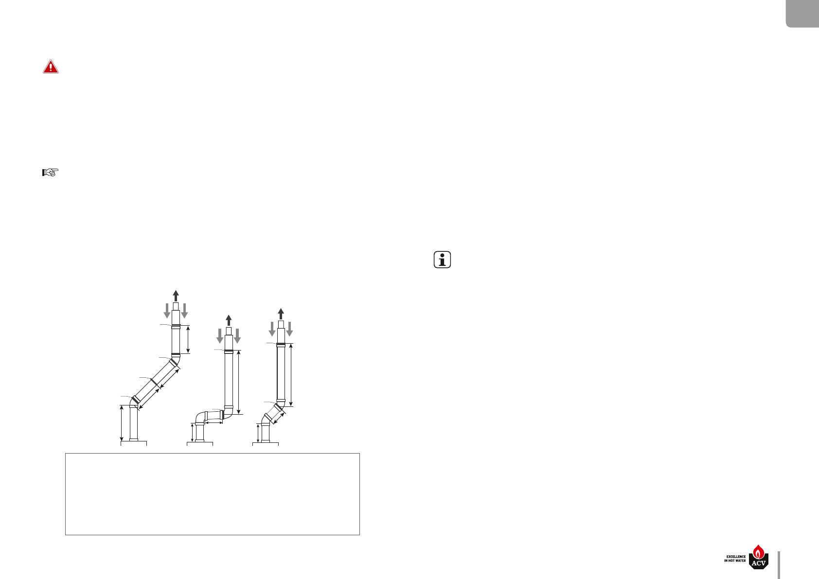
1. Each elbow and straight element will be secured at the sleeve.
2. In case the straight element before or after the first elbow is shorter than 25 cm,
secure the straight element after the elbow using a bracket.
3. In case a straight (horizontal or sloped) element is longer than 1 m, support the element in
its center using a clamp, making sure to allow free movement of the pipe.
4. Secure with a clamp every 2 meters in vertical piping/1 meter in horizontal/sloped
piping, making sure to distribute the clamps evenly on the length of piping.
If the appliance is provided with a condensate drain assembly, make sure to install
the complete assembly on the boiler. If the assembly is incomplete, replace the entire
assembly.
Make sure that the condensate drain assembly is filled with water before starting
up the boiler and check regularly the water level. Fill with water as necessary.
It is mandatory to ventilate the boiler room. The high or low air vent opening
dimensions depend on the boiler power and the boiler room size. Refer to the local
regulations in force.
If the combustion air inlet is located in an area likely to cause or contain
contamination, or if products which could contaminate the air cannot be removed,
the combustion air must be repiped and terminated at another location.
Pool, laundry, common household, and hobby products often contain fluorine
or chlorine compounds, which can form strong acids and corrode the internal
components and flue system.
In the case of parallel flue systems, make sure to maintain sufficient distance
(at least 40 mm) between the boiler flue piping and combustible materials, and
between the flue pipe and air inlet pipe if the latter is made of plastic material.
Do not use screws to fasten together any flue pipe elements or any PP air inlet
elements.
Do not bond piping elements together using glue (e.g. silicone) or foam (e.g. PUR).
General remark
For safety reasons and to make assembly easier, it is recommended to prefer the
use of concentric flue pipes when possible.
It is recommended to isolate the flue piping in damp rooms to prevent condensation
water from forming on the piping and drip.
When cutting the pipes to dimension, make sure to cut squarely and deburr the
edges to prevent seals from being incorrect or damaged.
To make piping assembly easier, exclusively use a mixture of water and soap (1%)
on the extremity of the pipe to be fit in.
When fitting metal flue pipes, make sure to always fit the pipe into the sleeve to
the end stop.
When fitting plastic flue pipes, make sure to allow material expansion by leaving
about 10 mm between the pipe end and the sleeve end stop.
Make sure to install the piping without any strain.
Make sure to install an inspection opening in the flue system.
When connecting the flue pipes, make sure not to exceed the maximum length
recommended for the product, otherwise the system power might decrease.
ACV-approved components will be used for the chimney connection. Failure to do
so will make any warranty claim void.
For C63 connection type (not allowed in Belgium), make sure to use the correct
piping material according to the resistance to temperature, pressure, chemical
composition of flue, condensation and soot. A code (as explained in EN 1443),
marked on the pipe, allows to determine if the material complies with the flue
system requirements.
N1 - N2 - N3 eco : A1005170 - 664Y7700 • B
EN
FR
NL
ES
IT
DE
PL
RU
en
11
TECHNICAL CHARACTERISTICS
N1 - N2 - N3 eco : A1005170 - 664Y7700 • B
en
12
EN
FR
NL
ES
IT
DE
PL
RU
TECHNICAL CHARACTERISTICS
N ECO CHIMNEY CONNECTION CHARACTERISTICS
Main Characteristics N1 eco N2 eco N3 eco
Flue pipe Ø mm 130 130 150
Available connection type B23
Essential recommendations for the correct operation of the appliance
The product must be installed and serviced by an approved and qualified engineer, in
accordance with applicable standards and regulations.
The chimney flue pipe diameter must not be smaller than that of the boiler flue reduction
collar. A flue disconnection piece is required.
Due to the high efficiency of our boilers, the flue gases exit at a low temperature.
Therefore, there is a risk that the flue gases condense and possibly damage the chimney.
It is thus strongly recommended to line the chimney. Please contact your installer for any
further information.
It is mandatory to ventilate the boiler room. The high or low air vent opening dimensions
depend on the boiler power and the boiler room size. Refer to the local regulations in
force.
B
23
E
A
B
F
C
D
FLUE PIPE CONNECTION TYPES
It is mandatory to use ACV flue systems to connect the appliance.
B23 : Connection to an exhaust duct that discharges the combustion products outside the room
where it is installed, with the combustion air being drawn directly from the boiler room.
Chimney N1 eco N2 eco N3 eco
E = 5 m Ø min. F mm 130 150 150
E = 10 m Ø min. F mm 130 130 150
E = 15 m Ø min. F mm 130 130 170
Fresh air supply
The boiler room must be provided with a high and a low fresh air supply .
Each user must make sure that the boiler room fresh air supply complies with the local
regulations in force.
For information, the table below indicates the values dened according to the Belgian regulation.
A. High-level fresh air supply
B. Low-level fresh air supply
C. Draught stabilizer
D. Manhole opening
E. Chimney height
F. Chimney diameter
Ventilation N1 eco N2 eco N3 eco
Fresh air supply m3/h 50 72 102
High-level air supply (A) cm2 150 150 150
Low-level air supply cm2 150 150 170
Recommended Lengths of Flue Pipes
N1 - N2 - N3 eco : A1005170 - 664Y7700 • B
EN
FR
NL
ES
IT
DE
PL
RU
en
13
TECHNICAL CHARACTERISTICS
ELECTRICAL CHARACTERISTICS
N1 - N2 - N3 eco
Main Characteristics
Rated voltage V~ 230
Rated frequency Hz 50
Electrical consumption Max. W 210
Electrical consumption in
standby
W 0
Rated current (Fuse) A 6
Class IP 20
1
t
1
2
4
t
t
L1 PEN
t
1211
7
4
2 3
5
6
8
9
L1
T2
T1
N
PE
M
Br
B
Bk G
G
Br
Bk
GBk
B
Y/Gr
B
R
G
B
Y/Gr
G V W B
Y/Gr
Y/Gr
Br
Y/Gr
B
Bk
G
L1
T1
T2
S3
B4
N
10
T1*
T2*
S3*
B4*
Boiler
N1 - N2 - N3 eco boiler wiring diagram
1. ON/OFF master switch
2. Minimum thermostat set at 45°C (T.O.D.)
3. Summer/winter switch
4. Manual reset high limit thermostat (103°C max.)
5. Burner
6. Safety cutout warning indicator
7. Room thermostat (option)
8. Installation heating pump (not provided)
9. Control thermostat of the boiler
10. Burner plug
B. Blue
Bk. Black
Br. Brown
G. Grey
V. Violet
R. Red
W. White
Y/Gr. Yellow/Green
SAFETY INSTRUCTIONS FOR THE INSTALLATION
Essential recommendations for safety
Install the boiler on a level base or vertically plumb support made of non-
combustible materials and of sufficient strength to support the boiler weight.
Use extreme care not to drop the boiler or cause bodily injury while lifting or
mounting the boiler onto the wall bracket or base. Once mounted, verify that the
boiler is securely attached to the bracket and wall or safely set on its base.
Do not use or store any flammable, explosive or corrosive products, such as paint,
solvents, salts, chloride products and other detergent products near the appliance.
Make sure that all air vents are unobstructed at all times.
Essential recommendations for the electrical safety
Only an approved installer is authorized to carry out the electrical connections.
Make sure that the appliance is connected to the earth.
Install a 2-way switch and a fuse or circuit breaker of the recommended rating
outside the appliance, so as to be able to shut power down when servicing the
appliance or before performing any operation on it.
Isolate the external electrical supply of the appliance before performing any
operation on the electrical circuit.
This appliance is not intended for use by persons (including children) with reduced
physical, sensory or mental capabilities, or lack of experience and knowledge,
unless supervised or unless they have been given instruction concerning the use
of the appliance by a person responsible for their safety.
Essential recommendations for the correct operation of the appliance
All connections (electrical, flue pipe, hydraulic, gas/fuel) must be carried out in
accordance with current standards and regulations in force.
The boiler must be installed in a dry and protected area, with an ambient
temperature comprised between 0 and 45°C.
Install the appliance to ensure easy access at all times.
Make sure that the mains water used to fill the boiler has a minimum pressure of 1.2 bar.
Make sure to install a pressure reducing valve set at 4.5 bar if the mains supply
pressure is in excess of 6 bar.
If works need to be performed (in the boiler room or close to the air vents), make
sure to turn off the boiler to prevent dust from entering and accumulating in the
boiler heating system.
GAS
pressure
(mbar)
N1 - N2 - N3 eco : A1005170 - 664Y7700 • B
en
14
EN
FR
NL
ES
IT
DE
PL
RU
INSTALLATION
PACKAGE CONTENTS
The appliances are tested and packaged on a wooden support. They are are delivered with a burner to
be installed.
At product reception and after removal of packaging, check the package contents and that
the appliance is free of damages.
TOOLS REQUIRED FOR THE INSTALLATION
Contents of package
N eco boiler.
Boiler Multilingual Installation, Operation and
Maintenance Instructions.
Oil burner
N1 eco with BMV3 burner,
N2 eco with BMV4 burner
N3 eco with BMV5 burner.
Burner Multilingual Installation, Operation and
Maintenance Instructions
OIL CONNECTION
General remark
The oil connection must comply with all applicable standards.
Essential recommendation for safety
Refer to the technical characteristics and safety instructions of the burner
technical manual. Failure to comply with the instructions could result in damage
to the material, personal injury or death.
Essential recommendations for the correct operation of the appliance
Bleed the oil duct and check thoroughly if all the boiler tubes, both internal and
external, are tight.
Control the oil supply connection and tightness.
N1 - N2 - N3 eco : A1005170 - 664Y7700 • B
EN
FR
NL
ES
IT
DE
PL
RU
en
15
INSTALLATION
BURNER INSTALLATION
Please refer to the burner manual to install the burner on the boiler, to connect the oil circuit
and get more information about the burner operation and maintenance.
N1 - N2 - N3 eco : A1005170 - 664Y7700 • B
en
16
EN
FR
NL
ES
IT
DE
PL
RU
INSTALLATION
ELECTRICAL CONNECTION
T2 S3T1
NL1 B4
T2S3 T1 N L1B4
2
M
N
PE230 V ~ 50HZ
L1
t
1
3
1. Room thermostat
2. System heating pump
3. Bridge (to be removed before installing
the room thermostat)
RECOMMENDATIONS FOR HYDRAULIC CONNECTIONS
Essential recommendations for safety
If the boiler is not equipped with one, the heating circuit of the system must be
fitted with an approved safety pressure relief valve, according to the pressure
mentioned on the type plate.
Use a two-wrench method when tightening field piping onto the boiler piping
connections. Use one wrench to prevent the boiler connections from the turning
and the second to tighten field piping. Failure to support the boiler piping
connections could damage piping or cause a leak.
Essential recommendations for the correct operation of the appliance
If the boiler is not equipped with one, make sure to install an expansion vessel
in the primary circuit, which is adapted to the boiler power/size and the type of
system.
General remark
The circuit illustrations are basic principle diagrams only.
HEATING CONNECTION
Typical connection - high temperature
1. Heating circuit isolating valve
2. Check valve
3. Heating pump of the system
4. Mixing valve
5. Safety group
6. Primary circuit filling valve
7. Heating circuit expansion vessel
8. Drain valve
9. Automatic air bleed valve
10. Bypass
11. Safety thermostat for floor heating circuit
Do not install thermostatic valves on
the radiators located in rooms fitted
with a room thermostat.
2
3
1
1
8
2
6
7
5
4
10
9
2
3 1
1
8
2
6
7
5
4 11
t
10
9
Typical connection - low temperature
Cold water
Hot water
N1 - N2 - N3 eco : A1005170 - 664Y7700 • B
EN
FR
NL
ES
IT
DE
PL
RU
en
17
INSTALLATION
Optional accessories are available to control a regular high or low temperature heating
circuit. For more information, contact your ACV representative.
SAFETY INSTRUCTIONS FOR STARTING UP
Essential recommendations for safety
The components inside the control panel may only be accessed by an approved
installer.
Set the water temperature in accordance with usage and local plumbing codes.
Make sure that the heating circuit filling valve is closed once the starting up
process is complete.
If there is a drain assembly, make sure that the condensate drain assembly is filled
with water before starting up the boiler. Fill with water as necessary.
Make sure that all connections are made and tight.
General remark
In normal operation, the burner starts automatically as soon as the boiler
temperature drops below the preset temperature.
FILLING THE HEATING CIRCUIT
If the system is fitted with an external hot water tank, first put the DHW circuit under
pressure before pressurizing the heating (primary) circuit. Refer to the hot water
preparation tank manual for more information.
Set-up conditions
External power supply isolated
DHW circuit (if any) under pressure
Filling procedure
1. Open the isolating valves (1).
2. Make sure that the drain valve (3) is tightly closed.
3. Open the  lling valve (2).
4. Make sure the air vent is open, as required.
5. Once the system is bled from air, bring the pressure to the static pressure between1.5 bar
and 2 bar.
6. Close the  lling valve (2)
Follow-on tasks
1. Check there is no leak.
Cold water
Hot water
1
3
1
2
N1 - N2 - N3 eco : A1005170 - 664Y7700 • B
en
18
EN
FR
NL
ES
IT
DE
PL
RU
STARTING UP
TOOLS REQUIRED FOR STARTING UP
CHECKS BEFORE STARTING UP
Essential recommendation for safety
Check the tightness of the flue pipe connections.
Essential recommendation for the correct operation of the appliance
Control the tightness of the hydraulic circuit connections.
N1 - N2 - N3 eco : A1005170 - 664Y7700 • B
EN
FR
NL
ES
IT
DE
PL
RU
en
19
STARTING UP
STARTING UP THE BOILER
Set-up conditions
All connections made
External power supply enabled
Oil supply open and circuit tight
DHW (if any) and heating circuits full of water
Procedure
1. Set the boiler thermostat between 60 and 90°C.
2. Put the summer/winter switch on "Winter".
3. Put the ON/OFF master switch on "ON".
4. Check with your hand (motor vibrations) that the heating pump of the system is not blocked and
unblock it if required.
Follow-on tasks
Adjust the combustion, see opposite.
COMBUSTION ADJUSTMENT
Set-up conditions
Operating boiler
Procedure
1. Refer to the Initial Operation instructions detailed in the technical manual of your burner.
2. Adjust CO
2
according to the values provided in the basic adjustment table below and by setting
the oil pressure as well as the air ap as described in the Initial Operation paragraph of the burner
manual.
3. Check the ue temperature and CO values according to the combustion characteristics (refer to
“Combustion characteristics” on page 9.
Follow-on tasks
Bleed the heating circuit again to restore a 1.5 bar pressure.
Repeat the sequence until complete evacuation of the air contained in the circuit.
Basic Adjustment table
Boiler/
Burner
model
Burner
Output
Oil
mass ow
Oil
nozzle
Oil
pressure
Fan
pressure
Air ap
scale
Bae
plate
scale
kW kg/h Usgal/h bar mbar % mm
N1 eco/
BMV3
25 2.11 0.60 60°H 10.0 2.5 30 6
N2 eco/
BMV4
32 2.70 0.60 60°H 14.5 2.5 32 9
N3 eco/
BMV5
43 3.63 1.00 45°H 12.0 2.5 46 10
RECOMMENDATIONS FOR THE BOILER MAINTENANCE
Essential recommendations for the electrical safety
Before opening the boiler for maintenance, turn off the boiler by pushing on the
ON/OFF master switch.
Isolate the external power supply of the appliance before performing any
operation, unless it is required to take measurements or perform system setup.
Essential recommendations for safety
Water flowing out of the drain valve may be extremely hot and could cause severe
scalding.
Do not use solvents to clean any of the burner components. The components could
be damaged, resulting in unreliable or unsafe operation.
Check the tightness of the flue pipe connections.
Essential recommendations for the correct operation of the appliance
It is recommended to have the boiler and the burner serviced at least once a year
or every 1,500 hours by a qualified technician, preferably at the start of the heating
season. More frequent servicing may be required depending on boiler use. Please
consult your installer for advice.
The boiler and burner maintenance will be carried out by a qualified engineer, and
the defective parts may only be replaced by genuine factory parts.
Make sure to replace any gaskets or seals on the removed components before
reinstalling them.
To ensure maximum efficiency and reliability of the unit, it is recommended that
the end-user perform the periodic checks mentioned in the Safety section of this
manual.
Control the tightness of the hydraulic circuit connections.
N1 - N2 - N3 eco : A1005170 - 664Y7700 • B
en
20
EN
FR
NL
ES
IT
DE
PL
RU
MAINTENANCE
TOOLS REQUIRED FOR MAINTENANCE
BOILER SHUT DOWN FOR MAINTENANCE
1. Switch the boiler o using the ON/OFF master switch and isolate the external power supply.
2. Close the oil supply valve of the boiler.
PERIODIC BOILER MAINTENANCE TASKS
Tasks
Frequency
Periodic
inspec-
tion
1 year 2 years
End-user Professional
1. Make sure that the system water pressure is at least 1 bar
when cold. Top up the system if necessary, adding small
quantities of water at a time. In case of repeated lls, call
your installer.
X X
2. Check that there is no water on the oor under the boiler.
Call your installer if there is.
X X
3. Check that all oil, hydraulic and electrical connections are
correctly fastened and tight.
X
4. Check the ue gas exhaust: correct fastening, correct in-
stallation, no leaks or clogging.
X
5. Check that there is no discoloured or cracked area on the
burner chamber plate.
X
6. Check the combustion parameters (CO and CO
2
), see the
burner manual.
X
7. Check visually the heating body: no evidence of corrosion,
soot deposits or damages. Carry out all required cleaning
tasks, repairs and replacements that might be required.
X
8. Check the burner nozzle and ignition electrode, refer to
the burner manual.
X
9. Remove the front panel, open the front door and clean
the combustion chamber, see “Cleaning the Combustion
Chamber” on page 21.
X
  • Page 1 1
  • Page 2 2
  • Page 3 3
  • Page 4 4
  • Page 5 5
  • Page 6 6
  • Page 7 7
  • Page 8 8
  • Page 9 9
  • Page 10 10
  • Page 11 11
  • Page 12 12
  • Page 13 13
  • Page 14 14
  • Page 15 15
  • Page 16 16
  • Page 17 17
  • Page 18 18
  • Page 19 19
  • Page 20 20
  • Page 21 21
  • Page 22 22
  • Page 23 23
  • Page 24 24

ACV N eco Operating instructions

Type
Operating instructions

ACV N eco is an oil-fired boiler designed to provide efficient and reliable heating for residential and small commercial applications. It features a compact design, easy installation, and user-friendly operation. The boiler is equipped with a range of advanced features, including a modulating burner for precise temperature control, a high-efficiency heat exchanger for maximum energy savings, and a built-in diagnostic system for easy troubleshooting. With its combination of performance, reliability, and ease of use, ACV N eco is an ideal choice for those seeking a dependable heating solution.

Ask a question and I''ll find the answer in the document

Finding information in a document is now easier with AI