Page is loading ...

4
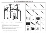
Ride Becken
Crash Becken
HiHat Becken
Tom2
Kick Drum
HiHat Controller
Snare Drum
D-TRONIC Q-5 Electronic Drumkit im Überblick
Tom1
Tom3
Drum-Modul
Drumrack

Kit No. Kitname Kit No . Kitname
Kit1 Standard -1 Kit14 Analog-1
Kit2 Standard -2 Kit15 Analog-2
Kit3 Dance-1 Kit16 Heavy Rock-1
Ki4 Dance-2 Kit17 Heavy Rock-2
Kit5 Dance-3 Kit18 Rockbank
Kit6 Jazz-1 Kit19 Rock
Kit7 Jazz-2 Kit20 Disco-1
Kit8 Room-1 Kit21 Disco-2
Kit9 Room-2 Kit22 Latin-1
Kit10 Electric-1 Kit23 Latin-2
Kit11 Electric-2 Kit24 Popreggae
Kit12 Brush-1 Kit25 Shortcut
Kit13 Brush-2 Kit26 - Kit30 User Kits
Teil 4: Anhang
20
1. Liste der Drumkits
Var 0 21-75
21 Surdo Mute
22 Surdo Open
23 Hi Q
24 Scratch Push
25 Scratch Pull
26 Finger Snap
27 Click Noise
28 Side Stick
29 Hand Clap
30 Ride Cymbal Cup
31 Tambourine
32 CowBell
33 Vibraslap
34 Bongo H
35 Bongo L
36 Conga H Mute
37 Conga H Open
38 Conga L
39 Timbale H
40 Timbale L
41 Agogo H
42 Agogo L
43 Cabasa
44 Maracas
45 Samba Whistle H
46 Samba Whistle L
47 Cuiro Short
48 Cuiro Long
49 Claves
50 Wood Block H
51 Wood Block L
32 CowBell
52 Guica Mute
53 Guica Open
54 Triangle Mute
55 Triangle Open
56 Shaker
57 Jingle Bell
58 Bell Tree
59 Seq Click L
60 Seq Click H
61 Brush Tap
62 Brush Swirl L
63 Brush Slap
64 Brush Swirl H
65 Snare Roll
66 Castanet
67 Snare L
68 Sticks
69 Bass Drum L
70 Open Rim Shot
71 Voice ‘One‘
72 Voice ‘Two‘
73 Voice ‘Three‘
74 Metronome Bell
75 Metronome Click
Var 1 21-51
21 Bass Drum Acoustic
22 Bass Drum Dance
23 Bass Drum Jazz
24 Bass Drum Room
25 Bass Drum Elec
26 Bass Drum Brush
27 Bass Drum Analog
28 Bass Drum Heavy
29 Bass Drum Disco
30 Bass Drum H
31 BD Rock 1
32 Gran Casa
33 Bass Drum L 1
34 Bass Drum Rock M
35 BD Rock 2
36 HQ Elec Kick
37 Jazz BD
38 Bass Drum 1
39 Bass Drum 2
40 Bass Drum 3
41 Bass Drum 4
42 Bass Drum L 2
43 Concert BD
44 BD Room
45 BD Rock 3
46 BD Rock 4
47 BD Rock 5
48 BD Dance1
49 BD Dance2
50 Bass Drum L 3
51 Bass Drum L 4
Var 2 21-51
21 Snare Acoustic
22 Snare Dance
23 Snare Jazz
24 Snare Room
25 Snare Elec
26 Snare Brush
27 Snare Analog
28 Snare Heavy
29 Snare Disco
30 Snare M
31 Snare H
32 SD Rock
33 SD Jazz H
34 Snare L
35 Snare H Hard
36 Snare Rock M
37 Snare Gate L
2. Liste der Klänge
Teil 4: Anhang .

Teil 4: Anhang
21
38 Snare Gate H
39 Snare Analog M
40 TR808 Snare Drum
41 Snare Drum 1
42 Snare Drum 2
43 Snare Rim
44 Studio
45 Classic
46 Snare Var
47 Snare Rock 1
48 Snare Rock 2
49 ClascElec
50 Snare Dance 1
51 Snare Dance 2
Var 3 21-74
21 Acoustic Tom H
22 Acoustic Tom M
23 Acoustic Tom L
24 Jazz Tom H
25 Jazz Tom M
26 Jazz Tom L
27 TR808 Hi Tom
28 TR808 Mid Tom
29 TR808 Low Tom
30 Disco Hi Tom
31 Disco Mid Tom
32 Disco Low Tom
33 Floor Tom L
34 Mid Tom L
35 High Tom 1
36 Rock Tom 1
37 Rock Tom 2
38 Rock Tom 3
39 Floor Tom H
40 Mid Tom H
41 High Tom 2
42 Room Tom var 1
43 Room Tom var 2
44 Room Tom var 3
45 Room Tom var 4
46 Room Tom var 5
47 Room Tom var 6
48 Rock Tom var 1
49 Rock Tom var 2
50 Rock Tom var 3
51 Rock Tom var 4
52 Rock Tom var 5
53 Rock Tom var 6
54 Natural Tom 1
55 Natural Tom 2
56 Natural Tom 3
57 HQ Low Floor Tom
58 HQ High Floor Tom
59 HQ Low Tom
60 HQ Low-Mid Tom
61 HQ Hi-Mid Tom
62 HQ High Tom
63 HQ Power Low Tom
64 HQ Power Mid Tom
65 HQ Power Hi Tom
66 Analog Tom 1
67 Analog Tom 2
68 Analog Tom 3
69 Elec Tom 1
70 Elec Tom 2
71 Elec Tom 3
72 Elec Low Tom
73 Elec Hi Tom 1
74 Elec Hi Tom 2
Var 4 21-51
21 Acoustic Cymbal
22 Acoustic Ride
23 Jazz Cymbal
24 Disco Cymbal
25 Heavy Ride
26 Ride Cymbal 1
27 Crash Cymbal 1
28 Ride Cymbal 2
29 Hand Cym.H Closed
30 Crash Cymbal 2
31 Ride Cymbal Cup
32 Crash Cymbal 3
33 Ride Cymbal 3
34 Crash Cymbal 4
35 Ride Cymbal 4
36 Crash Cymbal 5
37 Ride Cymbal 5
38 TR808 Cymbal
39 Cymbal Standard 1
40 Cymbal Bright
41 Cymbal Standard 2
42 Soft Cymbal 1
43 Soft Cymbal 2
44 Soft Cymbal 3
45 Soft Cymbal 4
46 Ride Standard 1
47 Ride Standard 2
48 Ride Standard 3
49 Ride Standard 4
50 Ride Bell 1
51 Ride Bell 2
Var 5 21-53
21 Acoustic HH Close
22 Acoustic HH Pedal
23 Acoustic HH Open
24 Dance HH Close
25 Dance HH Pedal
26 Dance HH Open
27 Elec HH Close
28 Elec HH Pedal
29 Elec HH Open
30 Heavy HH Close
31 Heavy HH Pedal
32 Heavy HH Open
33 Hi-Hat Closed 1
34 Hi-Hat Pedal 1
35 Hi-Hat Open 1
36 Analog HH Closed
37 Analog HH Pedal
38 Analog HH Open
39 Hi-Hat Closed 2
40 Hi-Hat Pedal 2
41 Hi-Hat Open 2
42 Hi-Hat Closed 3
43 Hi-Hat Pedal 3
44 Hi-Hat Open 3
45 TR808 HH Closed
46 TR808 HH Pedal
47 TR808 HH Open
48 Hi-Hat Open 4
49 Hi-Hat Closed 4
50 Hi-Hat Closed 5
51 Hi-Hat Closed 6
52 Hi-Hat Closed 7
53 Classical Hi-Hat Open

Teil 4: Anhang
Function
Basic Default
Channel Changed
Mode Default
Messages
Altered
Note
Number: True voice
Velocity Note ON
Note OFF
After Key‘s
Pitch Bender
Control Change 0, 32
1
5
6
7
10
11
64
65
66
67
80, 81
91, 93
100,101
121
Program
Change :True
System Exclusive
System: Song Position
: Song Select
Common: Tune
Aux: Local on/off
: All Notes Off
Messages: Active Sense
: Reset
Transmitted
1-16CH
1-16CH
Mode 3
X
**********
0 ~127
**********
0 9nH,v=1~127
0 8nH,v=0
X
X
0
X
X
O
O
X
X
X
X
X
X
O
O
X
X
0 0-127
0-127
X
X
X
X
X
O
X
X
Recognized
1-16CH
1-16CH
Mode 3
X
X
0 ~127
0 ~127
0 9nH,v=1~127
0 9nH,v=0 or 8nh
X
O
O
O
0
O
O
O
O
O
O
O
O
O
O
O *
O
0 0-127
0-127
X
X
X
X
O
O
O
O
Remarks
Bank Select
Modulation
Portamento Time
Data Entry
Volume
Pan
Expression
Sustain
Portamento
Sostenuto
Soft Pedal
DSP TYPE
DSP DEPTH
RPN LSB, MSB
Reset all Controllers
0 0-127
0-127
X
X
X
X
O
O
O
O
4. MIDI Implementation Chart
Mode1: OMNI ON, POLY Mode2: OMNI ON, MONO O: Yes Mode3: OMNI OFF, POLY Mode4: OMNI OFF, MONO X: NO
*Registered parameter number:
#0: Pitch sensivity
#1: Fine tuning cents
#2: Coarse tuning in half tones
23

Display Interpret
Pad
Effect
Copy
Trigger
Open Hi-Hat
Close Hi-Hat
Instrument
Level
Sensitivity
Threshold
Velocity Curve
Reverb
Chorus
Reverb Type
Reverb Level
Chorus Type
Chorus Level
Time Signatures
Click Sound
Record
Play
Clear
Room 1
Room 2
Room 3
Hall 1
Hall 2
Plate
Display Interpret
Delay
Pan Delay
Chorus 1
Chorus 2
Chorus 3
Chorus 4
Feedback
Flanger
Short Delay
FB Delay
Bass Drum
Snare
High Tom
Mid Tom
Low Tom
Ride
Crash
Hi-Hat
Hi-Hat Control
Normal
Dynamic
Easy
Fixed
Reset
Same
Individual
Demo 1
Demo 2
24
Teil 4: Anhang
5. Liste der LED-Abkürzungen

25
Teil 5: Technische Daten
Drum Pad:
4 Drum pads, 3 Cymbal pads, 1 Hi-Hat Control pedal, 1 BD Pad
Voices:
235 Voices
Drum kits:
25 Preset kits, 5 User kits
Song:
50 Preset songs, and 2 Demos
Effect:
Reverb, Chorus
Controls:
Power Switch, Start/Stop, Effect, REC/Play,Drum on/off, Click, Song, Pad, Kit, Tempo + / -, Enter,
Return
Display:
LED display
Connections:
DC in, MIDI out, MIDI in, Master out, AUX in, HH-Ctrl, HiHat, BD Kick, Snare, Tom 1, Tom 2, Tom 3,
Crash, Ride, Phones
Power Supply:
DC 9V
Teil 5: Technische Daten .

b2bMusic.biz GmbH
.
Postfach 20 10
.
35008 Marburg
.
Germany
.
www.b2bMusic.biz
www.d-tronic.info

27
Teil 3: Funktionsbeschreibung
Electronic Drumkit Q-5
User‘s Manual

28
Precautions:
WARNING! When using electric products, basic precautions should always be followed, including the following:
1. Read this manual completely before using the product.
2. Do not use this product near water - for example, near a bathtub, washbowl, kitchen sink, in a wet basement, or near a swimming pool,
or the like
3. This product should be used only with a cart or stand that is recommended by the manufacturer.
4. This product, either alone or in combination with an amplier and headphones or speakers, may be capable of producing sound levels
that could cause permanent hearing loss. Do not operate for a long period of time at a high volume level or at a level that is uncomfortable.
If you experience any hearing loss or ringing in the ears, you should consult an audiologist.
5. The product should be located so that its location or position does not interfere with its proper ventilation.
6. The product should be located away from heat sources such as radiators, heat registers, or other products that produce heat.
7. The product should be connected to a power supply only of the type described in the operating instructions or as marked on the product.
8. The power-supply cord of the product should be unplugged from the outlet when left unused for a long period of time.
9. Care should be taken so that objects do not fall and liquids are not spilled into the enclosure through openings.
10. The product should be serviced by qualied service personnel when:
a) The power-supply cord or the plug has been damaged; or
b) Objects have fallen, or liquid has been spilled onto the product; or
c) The product has been exposed to rain; or
d) The product does not appear to operate normally or exhibits a marked change in performance; or
e) The product has been dropped, or the enclosure damaged.
11. Do not attempt to service the product beyond that described in the user-maintenance instructions. All other servicing should be referred to
qualied service personnel.
Please observe the following instructions:
The lightning ash with arrowhead symbol within an equilateral triangle is in tended to alert the user to the
presence of uninsulated „dangerous voltage“ within the products enclosure that may be of sufcient magnitude
to constitute a risk of electric shock to persons.
The exclamation point within an equilateral triangle is intended to alert the user to the presence of important
operating and maintenance (servicing) instructions in the literature accompanying the product.
CAUTION! Due to risk of electric shock, do not remove the cover (or back panel)
of the apparatus! There are no user-serviceable parts inside the apparatus. Refer all
service to authorized service personnel.
CE mark for European Harmonized Standards
CE mark which is attached to our company’s products of AC mains operated apparatus until December 31, 1996
means it conforms to EMC Directive (93/68/EEC) and Low Voltage Directive (73/23/EEC).
CE mark which is attached after January 1, 1997 means it conforms to EMC Directive (89/336/EEC), CE mark Directive
(93/68/EEC) and Low Voltage Directive (73/23/EEC).
Also, CE mark which is attached to our company’s products of Battery operated apparatus means it conforms to
EMC Directive (89/336/EEC) and CE mark Directive (93/68/EEC).
Liability
The information contained in this owner‘s manual has been carefully compiled and reviewed. As we continuously
strive to improve our products, the technical data of the product may differ from descriptions in the manual. HEMINGWAY
is not responsible for such deviations and may implement changes without previous notice.
Warranty
All HEMINGWAY products are manufactured according to the electrical and mechanical guidelines of each country.
These products are warranted by the HEMINGWAY distributor only in each country. HEMINGWAY products without
a serial number is disqualied from the manufacturer‘s/distributor‘s warranty policy. This requirement is for the protection
and safety of the consumer.
PLEASE KEEP THIS SAFETY ADVICE SAFE!

2929
Sicherheitshinweis
Thank you for purchasing the D-TRONIC electronic drumkit Q-5. We hope
you‘ll enjoy playing your new instrument. For perfect operation and security,
please read the manual carefully and keep it for future references.

3030
Ride Cymbal
Crash Cymbal
HiHat Cymbal
Tom2
Kick Drum
HiHat Controller
Snare Drum
D-TRONIC Q-5 Electronic Drumkit Survey
Tom1
Tom3
Drum-Module

31
Part 1: Assembly Instruction 32
Part 2: Overview 36
Part 3: Functions 37
1. Setting up the drumkit 37
2. Adjusting the volume 37
2.1 Connecting headphones 37
2.2 Aux In-Input 37
2.3 Master Out Output 37
3. Main functions of the drum module 38
4. Choosing drumkits 38
5. Adjusting pads 38
5.1 Instrument 38
5.2 Level 39
5.3 Sensitivity 39
5.4 Threshold 39
5.5 Velocity 39
5.6 Conrming pad adjustments 39
6. Adjusting soundeffects 40
6.1 Reverb effect 40
6.2 Chorus effect 40
7. Copy drumkits 41
8. Metronome and tempo 41
8.1 Level 41
8.2 Time signature 41
8.3 Sound 41
8.4 Tempo 41
9. Song function 42
9.1 Choose songs 42
9.2 Adjust song level 42
9.3 Drum on/off 42
9.4 Adjust song tempo 42
10. Record and playback 42
10.1 Record 43
10.2 Play 43
10.3 Clear 43
11. Factory reset 44
12. MIDI 45
Part 4: List of functions 46
1. List of drumkits 46
2. List of sounds 46
3. List of songs 48
4. MIDI implementation chart 49
5. List of LED shortcuts 50
Part 5: Technical specications 51
31

(1)
(2)
1
(1)
(2)
2
1. Insert the right support into the base rack clamp, tighten
the set-screw.
2. Set up the knighthead, tighten the set-screw.
(1)
(2)(2)
3
1. Insert the mid-tube into left and right support rack clamps.
Tighten the set-screw with your drum key.
2. Set up the knighthead. Tighten the set-screw with
your drum key.
4
Insert the left and right support arm into the rack clamp as
shown above. Tighten the set-screw.
1. Insert the rod into the pad hole, set to a ne- position and
tighten the screw.
2. Insert the pad rod into rack clamp, set to a ne- position
and tighten the T-screw.
32
Part 1: Assembly instruction
32
Part 1: Assembly instruction .
Assembling the rack
1. Insert the left support into the base rack clamp, tighten the
set-screw.
2. Set up the knighthead, tighten the set-screw.
Assembling the pads
Assembling the cymbal- and the HiHat-pads
1
Insert the cymbal- and the HiHat-stands into the rack clamp
as shown above and tighten the T-screw.

1
2
Insert the module into the rack clamp, x it in a comfortable
position and tighten the screw.
1
Place the bassdrum-pad onto the plate 1, tighten the screw.
4
3
Set up the plates 3 and 4 and tighten the screw
2
3
1
2
4
3
Set up plate 1,2.3 and 4 as shown above and tighten
the screws.
4
Set up plate 2 on the backside of the pad and tighten the
screw.
33
Part 1: Assembly instruction
33
2
1. Take out the wing nut and felt washer.
2. Place the cymbal over the tilter peg. Put the felt washer and
wing nut onto the cymbal. Tilt the cymbal to your preference.
Assembling the module
Assembling the kick
1
HiHat
Cymbals
Crash + Ride
Cymbals

B D K I C K C R A S H R I D E T O M 3 T O M 2 T O M 1 S N A R E H I - H A T H H - C T R L
M A S T E R
O U T A U X I N
M I D I O U T M I D I I N
P O W E R
O N O F F
D C 9 V
Attach drum pedal to the batter side hoop with hoop holder
clamp and tighten the T-screw.
1
Insert the beater shaft into the beater link and tighten the
key bolt.
2
34
Part 1: Assembly instruction
34
CAUTION!
To prevent electric shock and damage to the devices, make
sure the power is switched OFF on the drum and all related
device before making any connection.
Connecting the pads and the pedals
Using the provided cables, connect each Trigger input jack
on the rear panel of the module and make sure each pad is
connected to its corresponding Trigger input jack..
with RIDE
with CRASH
with HI-HAT
with TOM1
with TOM2
with TOM3
with BD KICK
with HH CTRL
with SNARE
Assembling the bassdrum pedal
Connecting the pads to the drum-module

35
Part 1: Assembly instruction
35
Before you start playing .
Placement
The instrument should not be used or placed in dusty, damp, very cold or very warm environments and it should not be exposed
to direct sunlight or vibrations.
Interference
The instrument should not be used nearby of uorescent lamps or other sources of electrical interference. To avoid interference
to the microprocessors inside the instrument, do not use the instrument close to radios, TV‘s etc. In case the instrument does not
work properly, please switch it off and then switch it back on again after a few seconds.
Handle the instrument carefully
Never use unnecessary force when playing the drumkit or pressing down the pedals. Keep the instrument from falling over or being
dropped.
Caring and cleaning
Keep the instrument clean by wiping the surface with a dry folded cloth. Do not use coarse cleaning cloths, organic solvents or
combustible uids.
Foreign objects
Do not place liquid lled vases, vessels or glasses on the instrument. Spilled liquids can cause the instrument to short circuit or
catch re. This can cause irreparable damage to the instrument.

B D K I C K C R A S H R I D E T O M 3 T O M 2 T O M 1 S N A R E H I - H A T H H - C T R L
M A S T E R
O U T A U X I N
M I D I O U T M I D I I N
P O W E R
O N O F F
D C 9 V
MASTER
PHONES
AUX IN
MIN
MAX
MIN
MAX
MIN
MAX
VOLUME CONTROLS
HH-CTRL
HI-HAT
BD-KICK
SNARE
TOM1
TOM2
TOM3
CRASH
RIDE
ENTER
TEMPO
EFFECT
KIT
PAD
CLICK
DRUM
ON/OFF
REC/
PLAY
START/
STOP
SONG
1
2
3
4
5
6
7
8
9
10 11 12 13
14
36
Part 2: Overview
Part 2: Overview .
36
Top panel:
go to page
1 POWER switch Turns the instrument on and off 37
2 VOLUME pots Control volume of the drumset 37
3 TEMPO button Adjusts the tempo of the metronome or a song 41, 42
4 JOGDIAL wheel Adjusts several parameters 38
5
+/-
buttons Adjust several parameters 38
6 ENTER/BACK buttons Control the navigation in the menu 38
7 SONG and REC/PLAY unit Activates/deactivates and edits record and playback functions 42, 43
8 KIT and METRONOME unit Adjusts drumkit and metronome functions 38, 41
9 PHONES jack Connects a pair of headphones 37
Rear panel:
go to page
10 TRIGGER Input Connects the pads and pedals 34
11 AUX IN jack Connects external audio equipment 37
12 MASTER OUT jack Transfers signals to external audio equipment 37
13 MIDI IN/OUT jacks Connect the drum module to other MIDI compatible equipment 45
14 POWER jack Connects the power supply 37
Top panel
Rear panel

DC 9V
PHONES JACK
A U X I N
CD player
MASTER
OUT
AMPLIFIER
Part 3: Functions .
1. Setting up the drum kit
To turn the drumkit on and off, use the POWER switch located
on the left side of the drum module. When the drum kit is
turned on, the number of the selected drumkit will appear in
the LED-display.
Connect the module to a power socket
carrying the correct voltage (indicated
on the rear panel). Use the enclosed
power cord. Never connect the module
to a power socket that is also supplying
power to electric engines or big dome-
stic appliances. Always avoid connec-
ting too many electric devices to the
same power socket.
2. Adjusting the volume
There are several ways to listen to the sound of your electro-
nic drumset. By turning the volume pots you can adjust your
preferred volume level.
Start playing at low volume and then increase the volume to
desired level. Do not set the speaker volume level too high.
2.1 Connecting headphones
A pair of headphones can be connected to the drum modu-
le. The headphone jack is located on the front panel of the
module. Connect the headphones to the module and use the
PHONES fader to adjust the headphone volume level.
2.2 Aux In Input
Through the AUX IN Input jack an external sound source, for
example a CD-/MP3-Player, may be connected to the drumkit
and amplied by the module. This makes it possible to playa-
long to the music played by the CD-Player. Use the AUX IN
fader to adjust the volume level of the external sound source.
2.3 Master Out Output
The MASTER OUT jack can be used to deliver the output of the
drumkit to a stereo sound system, mixing console or recor-
ding device. The MASTER OUT level can be adjusted by using
the MASTER volume pot.
37
Part 3: Functions
37

4. Choosing drumkits
The module offers 25 kit presets and 5 user-kits. If you press
the KIT button you can use the JOGDIAL or the + /- buttons
to select a kit. The selected kit, as shown on the LED Display,
can be played immediately. The Kit-mode is automatically set,
when you switch on the power of the module.
5. Adjusting pads
Every pad of the drumkit can be adjusted individualy. Just
choose the Pad-mode and conrm it with the ENTER-button.
Select the pad (HHC, HH, BD, SN, T1, T2, T3, Cr, R1) you want
to adjust and conrm this by pressing the ENTER-button. You
can also choose the pad by hitting it with the drumstick. Al-
ways conrm your choice with the ENTER-button.
3. Main functions of the drum module
The console is easy to use and very comfortable in handling.
By using the ENTER and BACK buttons you can switch bet-
ween the layers of the menu. The next submenu can be acti-
vated by pressing the ENTER button. The BACK button leads
you to the previos menu again. To save certain parameters
you can also use the ENTER button
Pressing the + /- buttons or turning the JOGDIAL makes it
easy to navigate through the chapters of the menu or to adjust
your favourite parameters.
For each pad the parameters for Instrument, Level, Sensivity,
Threshold and the Velocity Curve can be individually adjusted
5.1 Instrument
The sound of the pad can be adjusted with the Instrument
(InS) function. You can generate a specic sound for each
pad, by pressing the + /- buttons or using the JOGDIAL. The
sound can also be changed by hitting the pad as long as you
have reached your favourite sound.
38
Part 3: Functions
38
Category of Instruments
(1 - 6)
Sound
refer to the list of sounds on pages 42-43

Normal Easy Dynamic
There are 6 categories of instruments, which turn up as the
rst number of the LED-display. The next two numbers show
the certain instruments. You can choose between several
sounds in each category (refer to the list on page 46).
5.2 Level
Level (Lvl) adjusts the sound intensity of each pad in a range
between 02 – 32. This function makes it possible to adjust the
relationship of loudness between the pads.
5.3 Sensitivity
Sensitivity (Sen) adjusts the touch sensitivity of the pads in a
range between 01 – 08. With this function you can take inu-
ence on the reaction of the pad, when you produce intended
or unintended doublebeats (double trigger). The higher the
value, the more precise the pad reacts. If you want to play
fast strokes for example, you should adjust a higher sensivity
value.
5.4 Threshold
Threshold (Thr) allows a trigger signal to be received only
when the force struck on the pad is above a determined force
level (velocity). This can be used to prevent a pad from soun-
ding because of vibrations of other pads. Therefore the pad
doesn‘t produce sound when the pad is struck lightly and a
high value is adjusted. The range is between 000 - 050.
5.5 Velocity
The Velocity Curve (CUr) adjusts the dynamic range of the
pads.
Nor – Is dened as a curve in which the level of the sound
developes linear to the force of attack. The harder the attack,
the louder the sound.
Easy – Is dened as a curve which makes it easier to play
loudly. The curve generates higher velocities for less force.
Dynamic – Is dened as a curve which makes it easy to play
quietly. The curve generates lower velocities for hard force.
Fixed – Means that regardless of how hard you play, the pad
will transmit always the same level of velocity.
5.6 Conrming pad adjustments
It‘s up to your decision, if the adjustments for Sensivity,
Threshold and Velocity, are binding for all Kits or just binding
for one Kit.
Go to the Kit-mode and choose the Trigger Follow Setting
submenu by pressing the ENTER-button. Select the adjust-
ment Same or Individual and conrm your choice with the
ENTER-Button.
Same – The parameter adjustments Sensivity, Threshold and
Velocity are binding for all Kits.
Individual – The parameter adjustments Sensivity, Threshold
and Velocity are only binding for the actually chosen Kit.
39
Part 3: Functions
39
/