Page is loading ...

© 2017 Precision Digital Corporation.
All rights reserved.
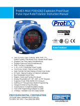
Congratulations on your purchase of
the ProtEX PD6830 Explosion-Proof
Pulse Input Rate/Totalizer!
This quick start guide will briey
describe some of the common setup
procedures for this meter.
This guide includes:
Basic ProtEX Meter Wiring....................
Program Pulse Input and Totalizer.........
Program Open Collector Pulse Output....
Program Open Collector Alarm Output....
Program 4-20 mA Analog Output...........
Return Meter to Factory Defaults...........
For additional information about the
ProtEX PD6830 meter not covered in
this quick start guide, please consult
the instruction manual included on the
CD or available at www.predig.com.
Menu Button – Use this button to
access Programming Mode and
return to the previous menu.
Enter Button – Use this button to
access or accept a menu item while
in Programming Mode.
Reset Button – Use this button to
select the previous menu option or
change the selected digit while input-
ting a numeric value in Programming Mode.
While in Run Mode, use to reset the total.
Display Button – Use this button to
select the next menu option or incre-
ment the selected digit while input-
ting a numeric value in Programming Mode.
While in Run Mode, use to cycle through
alternate variables such as maximum, mini-
mum, and grand total.
2
3
5
6
7
8
233 South Street
Hopkinton MA 01748-2208 USA
Tel. (508) 655-7300 www.predig.com
TM
RTP
IEC Ex
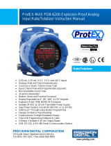
ProtEX PD6830 Explosion-Proof
Pulse Input Rate/Totalizer
Quick Start Guide

2
The connector labels, printed on the electronics module of the meter, show the location of all
available connectors. Connect your wires to the screw terminals of the meter as indicated.
Basic ProtEX Meter Wiring
4-20 mA Output Wiring
1
The images below show wiring for a 4-20 mA
output.
Open Collector Output
The below image shows wiring for the open
collector output.
DC Power Connection
The below image shows wiring for a DC power
connection to the meter.
1
ProtEX models with 4-20 mA output option (PD6830-XXA/B)
Consult the PD6830 instruction
manual located on the included CD or
available online at www.predig.com
for additional wiring diagrams.
Pulse Input Wiring
The image below shows wiring for a owmeter
powered by an external power supply (active).
The image below shows wiring for a isolated
owmeter powered by an external power supply.
The image below shows wiring for a self-powered
magnetic pickup coil owmeter.
Total Reset Connection
The below image shows wiring for an external total
reset switch or push button.
The image below shows wiring for an NPN open
collector input.
The image below shows wiring for a PNP sensor
with external power.
LP- LP+
Power
Supply
4-20 mA Input
Device
Power
Supply
COM
RST
P+
S+ S-
COM
RST
P+
S+ S-
+1.8 V
2 MOhm
Internal Pullup
Flowmeter
(Pulse Output)
Power
Supply
COM RST
P+
S+ S-
INPUT LEVEL
mV V ISO
Flowmeter
(Pulse Output)
Power
Supply
COM RST
P+
S+ S-
INPUT LEVEL
mV V ISO
Flowmeter
(Magnetic Pickup Coil)
COM
RST
P+
S+ S-
INPUT LEVEL
mV V ISO
+3.0 V
100 kOhm
Internal Pullup
NPN
SENSOR
COM
RST
P+
S+ S-
INPUT LEVEL
mV V ISO
100 kOhm
Internal Pull-Down
PNP
SENSOR
Power
Supply
COM
RST
P+
S+ S-
INPUT LEVEL
mV V ISO
ProtEX PD6830 Rate/Totalizer Quick Start Guide

3
Program Pulse Input and Totalizer
These instructions show you how to program the ProtEX meter to accept a pulse input and display a value. The
owmeter you are using in your facility will have a K-Factor assigned to it by the manufacturer. This is either
notated on the owmeter itself or somewhere in the instruction manual included with the owmeter. This num-
ber is necessary in order to tell the ProtEX meter how many pulses it will receive depending on the ow rate.
For example: If the K-Factor of your owmeter is 210, meaning that for every U.S. gallon of ow per second it
will transmit 210 pulses, then you should enter the value 210.000 at the FActor (K-Factor) menu during
this setup procedure.
Note: K-Factors are almost always given in U.S. gallons. Make certain that you take the unit of measure used
by the owmeter manufacturer into account when programming the ProtEX meter.
Note about SafeTouch
®
through-glass buttons
The ProtEX Series of meters are equipped with four SafeTouch
®
through-glass buttons which al-
low it to be programmed and operated without removing the cover. To activate a button, press one
nger to the glass directly over the marked button area.
Press to enter Pro-
gramming Mode, press
to access the SETUp
(Setup) menu.
Press
to access the
InPut (Input) menu.
Press
to select
the appropriate input
type (e.g. active, NPN,
PNP, coil, isolated, etc.)
depending upon your
wiring conguration,
press
to accept.
Press
to access the
FActr (K-Factor) menu.
Note: The information
entered during the
next three steps is
related to the K-Factor
assigned to your
specic owmeter.
Press to select the
appropriate factor unit of
measure (e.g. pulses per
gallon, pulses per liter,
etc.), press
to accept.
Press
to select an
appropriate decimal
point location for your
K-Factor, press
to
accept.
Using
to select a digit
and
to increment the
selected digit, enter your
owmeter's K-Factor.
Press
to accept.
Note: The number entered during step 7 is
the K-Factor assigned to your specic
owmeter. This number is notated on the
owmeter itself or somewhere in the instruc-
tion manual included with the owmeter.
This number is necessary in order to tell
the ProtEX meter how many pulses it will
receive depending on the ow rate.
1
2
3
4
5 6
7
ProtEX PD6830 Rate/Totalizer Quick Start Guide

4
Press
to access the
UnitS (Units) menu.
Note: The units menu allows
you to enter the unit
types used to mea-
sure your rate, total,
and grand total.
Press to access
the tbASE (Time Base)
menu.
Press
to select the
appropriate time base for
your measurement (i.e.
units per second, minute,
hour, or day), press
to accept.
Press
to access
the rAtEU (Rate Units)
menu.
Press
to select the ap-
propriate unit of measure
(e.g. gallons, liters, etc.) for
your rate measurement,
press
to accept.
Note: Consult the instruction manual for a full list of
available units of measure.
Press to access
the tot U (Total Units)
menu.
Press
to select
the appropriate unit of
measure (e.g. gallons,
liters, etc.) for your total
measurement, press
to accept.
Press
to select the
appropriate multiplica-
tion factor for your total
calculation, press
to
accept.
Note: This is the number by which the rate will be
multiplied before being added to the total. The
default is X1, meaning that the rate will be
multiplied by 1.0 before being added to the
total. You have the option of multiplying by
100, 1,000, or one million.
Repeat steps 13 through
15 to set the grand total
units and multiplication
factor.
Press
to access the
dEc.Pt (Decimal Point)
menu.
8 (Pulse In Continued) 9
10 11
12 13
14 15
16 17
ProtEX PD6830 Rate/Totalizer Quick Start Guide

5
Press
to access
the rAtE (Rate Decimal
Point) menu.
Press
to select the
appropriate decimal
point location for your
rate measurement,
press
to accept.
Press
to access the
totAL (Total Decimal
Point) menu.
Press
to select the
appropriate decimal
point location for your
rate measurement,
press
to accept.
Repeat steps 20 and
21 to set the grand total
decimal point location.
Press and hold
to
return the meter to Run
Mode.
Program Open Collector Pulse Output
These instructions show you how to program the ProtEX meter to output the rate as pulse
signals from the two NPN open collector outputs based on programmed parameters.
Note: Additional pulse output options not covered in this quick start guide, including totAL (Total), Grtot
(Grand Total), rEtr (Retransmit), quAd (Quadrature), and tESt (Test), are covered in detail in the
PD6830 instruction manual.
Press and hold until
the meter displays
ADVANCE (Advanced).
The meter is now in the
Advanced Features menu.
Press
to access the
OUTPUT (Output) menu.
Press
to select
the output you want to
program (Output 1 or
Output 2), press
to
access.
Press
to select the
PULSE (Pulse) menu,
press
to access.
18 (Pulse In Continued) 19
20
21
22
23
1
2
3
4
ProtEX PD6830 Rate/Totalizer Quick Start Guide

6
Press
to access the
rAtE (Rate) menu.
Press
to select an
appropriate decimal
point location for the
output pulse count,
press
to access.
Using
to select a digit
and
to increment the
selected digit, enter the
output count. Press
to accept.
Note: The number entered during step 7 is the
output pulse count, or the number of pulses
that should be outputted per input pulse (ad-
justed by input K-Factor). For a 1-to-1 ratio,
the count should be set to 1. Otherwise, the
output will be calculated as follows:
Program Open Collector Alarm Output
These instructions show you how to program the ProtEX meter to output an alarm state via
the two NPN open collector outputs based on programmed set and reset points.
Press and hold until
the meter displays
ADVANCE (Advanced).
The meter is now in the
Advanced Features menu.
Press
to access the
OUTPUT (Output) menu.
Press to select
the output you want to
program (Output 1 or
Output 2), press
to
access.
Press
to select the
ALrnm (Alarm) menu,
press
to access.
Press
to select the
output parameter, press
to access.
Note: rAtE, totAL, and
Grtot will output
alarm states related
to the rate, total, or grand total. On and OFF
will force the output alarm into either the on
or o alarm state.
Press to access the
SEt (Set Point) menu for
your chosen parameter.
Note: This menu will allow
you to program the
value at which the
selected parameter will trigger the alarm.
The reset point is the value at which the
parameter will deactivate the alarm state.
Input Pulses
Input K-Factor
Count
Number of Output Pulses =
( )
5 (Pulse Out Continued) 6
7
1
2
3
4
5 6
ProtEX PD6830 Rate/Totalizer Quick Start Guide

7
Program 4-20 mA Analog Output
These instructions show you how to program the ProtEX meter to output an analog signal
based on a desired parameter. This signal is commonly output to a PLC or chart recorder.
Note: This feature is only available on certain PD6830 models. Please consult the footnote in the wiring sec-
tion or the ordering information section of the instruction manual for models that include this option.
Using to select a digit
and
to increment the
selected digit, enter the
desired set point. Press
to accept.
Press
to access
the rESEt (Reset Point)
menu for your chosen
parameter.
Using
to select a dig-
it and
to increment
the selected digit, enter
the desired reset point.
Press
to accept.
Note: Programming the set point to be greater
than the reset point will result in a high
alarm (meaning the alarm will turn on when
the value is greater than the set point).
Programming the set point to be less than
the reset point will result in a low alarm.
Note: The alarm status will show on the display
even if the output is not wired.
Press and hold until
the meter displays
ADVANCE (Advanced).
The meter is now in the
Advanced Features menu.
Press
until the
A OUT (Analog Output)
menu is displayed,
press
to access.
Press
to select the
parameter you want to
output (i.e. rate, total, or
grand total), press
to access.
Press
to access the
dSP 1 (Display 1) menu.
This is the value at
which the low end of the
analog signal range will
be output.
Using
to select a dig-
it and
to increment
the selected digit, enter
the desired display value.
Press
to accept.
Note: The following menus will ask you to program
display and output values. A display value
is the process value being displayed by the
meter. An output value is the current in mA
that the meter should output at that display
value. Display 1 represents the low end of
the display value range while display 2 is
the high end. Output 1 is the low end of the
analog output and output 2 is the high end.
7 (Alarm Out Continued)
8
9
1
2
3
4
5
ProtEX PD6830 Rate/Totalizer Quick Start Guide

LIM6830QS_C - 06/178
Return Meter to Factory Defaults
If a mistake has been made while programming the meter and it is unclear where the error
occurred, the best option may be to perform a factory reset of the meter and begin again.
These steps show how to perform a factory reset of the ProtEX meter.
Press and hold
until
the meter displays
ADVANCE (Advanced).
The meter is in the Ad-
vanced Features menu.
Press
until the
SYSTEM (System) menu
is displayed, press
to access.
Press
until the
BACKUP (Backup) menu
is displayed, press
to access.
Press
until the
dEFLt (Defaults) menu
is displayed, press
to accept.
Press
again when
the meter ashes rESEt
DFALTS? (Reset De-
faults?) to conrm.
The meter has been
reset to its default
settings. You can now
begin programming the
meter again.
Using
to select a digit
and
to increment
the selected digit, enter
the desired output value.
Press
to accept.
Repeat steps 4 through
7 for the high end of
the display (dSP 2) and
output (OUt 2) ranges.
Once dSP 2 and OUt 2
have been programmed,
press
to save the
programmed settings to
memory.
Press
to access the
OUt 1 (Output 1) menu.
This is the value in mA
which will be output at
dSP 1 (Display 1).
1
2
3
4
5
6
7
8
9
6
(4-20 mA Out Cont.)
ProtEX PD6830 Rate/Totalizer Quick Start Guide
/