Page is loading ...

SPECIFICATIONS
Receiver—
Range: -14.2 to 158.0 °F / -9.9 to 70.0 °C
Resolution: 0.1°
Remote —
Ambient range: -22.0 to 158.0 °F / -30.0 to 70.0 °C
Probe range: -58.0 to 158.0 °F / -50.0 to 70.0 °C
Resolution: 0.1°
RF transmission—
Frequency: 433 MHz
Range: Up to 100 feet (30 meters)
Rate: Every 30 seconds
Remotes: Up to 3 (1 remote included)
Compliance: This product complies with
standardsandspecicationsof
BZT, FCC and article number
334 of PTT.
REMOTE - BATTERY INSTALLATION AND
CHANNEL SELECTION
Install the batteries into the remote(s) before
doing so for the receiver.
1. Remove the battery compartment.
2. Select the channel number using the CHANNEL
slide switch.
Note: When using multiple remotes, make certain
to assign different channels to each remote.
Once a channel is assigned to a remote, it
can only be changed by removing the
batteries to reset the unit.
3. Select the temperature display mode using the
°C/°F slide switch.
4. Insert the 2 each AAA batteries according to the
polarity shown in the battery compartment.
5. Replace the battery compartment door.
RECEIVER - BATTERY INSTALLATION
Install the batteries into the remote(s) before
doing so for the receiver.
1. Remove the battery cover.
2. Insert the 2 AA batteries according to the polarity
shown in the battery compartment.
3. Replace the battery cover.
REMOTE MODULE SENSORS
The remote module has two sensors, an external/
bottle probe sensor and an internal/ambient sensor.
Only 1 sensor operates to transmit data. When
the probe is plugged in to the remote, the probe
temperature is measured/transmitted, when the probe
is unplugged, the ambient temperature is measured/
transmitted.
The external bottle probe sensor is designed for use
inrefrigeratorsandfreezers.Thesolutionlledbottle
simulates the temperature of other stored liquids. The
bottleprobeislledwithanontoxicglycolsolutionthat
is GRAS (Generally Recognized As Safe) by the FDA
(Food and Drug Administration) eliminating concerns
about incidental contact with food or drinking water.
Velcro® and a magnetic strip are provided to mount
the bottle to the inside of a refrigerator/freezer. (Do
not immerse bottle probes in liquid).
Both the remote module and bottle probe may be
placed inside the refrigerator or the bottle probe may
be placed inside the refrigerator/freezer and the
remote may be located outside of the refrigerator/
freezer door. The micro-thin probe cable permits
refrigerator/freezer doors to close on it.
The internal (ambient) sensor is located inside the
case of the remote module. It is ideal for monitoring
ambient air temperatures.
OPERATION
Once batteries are installed, the remote(s) will start
transmitting temperature readings at 30-second
intervals.
The receiver will start searching for signals once
batteries are installed. Upon successful reception,
the individual channel temperatures will be displayed
on the top line and the ambient temperature will
be displayed on the bottom line. The receiver will
automatically update its readings at 30-second
intervals.
Position the remote and receiver within the effective
transmission range, which, in usual circumstances is
50 to 100 feet (15 to 30 meters). The effective range
issignicantlyaffectedbybuildingmaterialsand
the remote/receiver location/positioning. Try various
setups for best results. (See the “Troubleshooting”
section)
If no signals are received, blanks “- - -” will be
displayed for the remote channel.
If no readings are received for a channel for more
than 2 minutes, blanks, “- - -” will be displayed until a
remote signal search is performed.
To force a remote signal search, press the CHANNEL
and MEM buttons simultaneously. This is useful in
synchronizing the transmission and reception of the
remote and receiver. Repeat this step whenever you
nddisplaydiscrepanciesbetweenthereceiverand
remote.
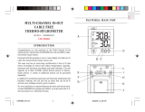
RECEIVER DISPLAY
The receiver has a built in internal (ambient)
temperature sensor used to display the ambient air
temperature. The ambient temperature is shown on
the bottom portion of the display.
The remote readings, corresponding remote channel
and temperature trend are shown on the top portion
of the display.
Press the CHANNEL button to switch from one
remote channel to another.
The temperature trend indicator shows the trend of
readings at the remote. There are three possible
trends that will be displayed, rising, steady, and
falling.
If the temperature goes above or below the
temperature measuring range, the display will show
“HHH” or “LLL”.
The reception icon shows the signal receiving status
of the receiver:
Successful Reception
Search Mode
No Signal
DISPLAYING °F OR °C (RECEIVER)
To display the temperature readings on the receiver
in Fahrenheit or Celsius, slide the °C/°F switch to the
desired position. The °F/°C display selection for the
remote module(s) is independent of the receiver.
MINIMUM AND MAXIMUM MEMORY
The ambient temperature at the receiver and the
temperatures transmitted from the remote(s) are
automatically recorded into memory.
Minimum and maximum temperature memories
are NOT programmable. The minimum temperature
recorded into memory is the minimum temperature
achieved since the last time the memory was cleared.
The maximum temperature recorded into memory is
the maximum temperature achieved since the last
time the memory was cleared. The minimum and
maximum temperature memories are maintained over
the period since the memory was cleared.
VIEWING MIN/MAX MEMORY
1. Press the CHANNEL button to select the desired
remote module.
2. Press the MEM button once to display the maximum
temperature (MAX will appear on the display).
3. Press the MEM button again to display the
minimum temperature (MIN will appear on the
display.
4. Press the MEM button again to return to the
current temperature display.
CLEARING THE MIN/MAX MEMORY
To clear the MIN/MAX memory, press the CLEAR
button, all segments of the display will appear for 2
seconds.
ALARMS (REMOTE MODULE READINGS)
Remote module alarm limits may be set in 1°
increments. Remote module alarm limits are set
independent of each other.
With the alarm values set:
-The receiver will sound an alarm when the
temperature measured is outside the alarm limits that
have been set (equal to or lower than the low alarm
set point, or equal to or greater than the high alarm
set point).
-The display will switch to the respective remote
channelwiththedisplayashing.TherespectiveHI/
LO indicator(s) will appear to signify the status of the
alarm.
-The alarm will sound regardless of which remote
sensor is being displayed and regardless of the
display mode.
-If the temperatures measured are outside the alarm
limits that have been set for more than one channel,
the alarm will sound with the display alternating
from one alarming channel to another at 5-second
intervals.
If undisturbed, the alarm will sound for one minute.
Press any key to mute the alarm momentarily.
To completely disable the alarm, select the channel
and press the ON/OFF TEMP AL button to turn it off.
SETTING THE TEMPERATURE ALARM LIMITS
1. Press the CHANNEL button to select the desired
remote channel.
2. Press the HI/LO button for the upper (HI) or lower
(LO) limit.
“OFF” will be displayed if the alarm for that limit is
turned off. Press the TEMP AL ON/OFF button to
turn on the alarm limit.
3. Press the button to set the upper and/or lower
temperature alarm limits.
4. Press HI/LO button to set another limit or return to
normal display.

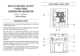
TRACEABLE
RADIO SIGNAL
REFRIGERATOR
THERMOMETER
INSTRUCTIONS
®
PLACEMENT/MOUNTING OPTIONS
Also included:
Magnet - A magnet is supplied for the remote module.
Peel the protective paper off the adhesive tape on
the magnet. Press the magnet onto the back of the
remote and mount on any metal surface.
Hook & Loop - Self adhesive hook and loop
mounting tape is supplied with the remote. Peel
off the protective backing. Adhere one piece to the
remoteandtheothertoanyclean,atsurface.
TRANSMISSION COLLISION/INTERFERENCE
Signals from other radio devices may interfere with
those of this product and cause temporary reception
failure. This is normal and does not affect the general
performance of the product. The transmission and
reception of temperature readings will resume once
the interference recedes.
All radio signals are inherently affected by
interference or blockage. Performance is best when
there is little or no interference or blockage. Some of
the causes of interference and blockage are metal,
reectivesurfaces,motors,elevators,orescent
lights with electric ballasts, sparking environments,
emergency radios, power lines, portable/mobile
radio transmitters and walkie-talkies. On occasion,
momentary interference with the remote transmitter
may cause an erroneous minimum or maximum
readings to be captured by the receiver.
If two or more remotes in the same area are set to the
same channel then any or all receivers will probably
receive scrambled signals and report erroneous
readings.
TROUBLESHOOTING
If the receiver is not obtaining a signal from the
remote(s), or if without obvious reasons, the display
for a particular channel goes blank, press the
CHANNEL and MEM button simultaneously to force
an immediate remote signal search.
The remote transmitter sends a signal to the main
receiver every thirty seconds. Wait at least two
minutes to see if a signal has been received before
continuing with the additional troubleshooting steps.
If the receiver is not able to receive the remote signal:
1. Check the remote to see that it is still in place.
2. Check the batteries of both the remote and the
receiver.
3. Verify that the transmission distance is within range
and the path is clear of obstacles and interference
(shorten the distance if necessary).
4. Make certain that the channel number displayed on
the remote matches the channel number indicated
on the receiver.
5. If there are two or more remote transmitters, make
certain that they are not set to the same channel.
Additional Steps--
Check to make certain that the unit will pick up a
nearby signal:
1. Place the remote and receiver in a vertical position
approximately 6 feet away from the each other with
no obstructions between the units.
2. Make certain the main receiver is set to display the
correct remote channel.
3. On the receiver simultaneously press the
CHANNEL and MEM button to force a signal
search.
If, after waiting at least 2 minutes, the main receiver
displays the temperature from the remote transmitter,
the units are functioning properly and will perform
within their limitations.
If after performing the above steps, the units do not
perform when placed further apart, try the following.
– Place the remote as high as possible.
– Place the remote in a vertical/stand-up position.
– Place the receiver in a vertical/stand-up position.
– Place the remote and the receiver in locations
where the radio signal does not need to be sent
through metal panels, thick walls, multilevels, etc.
– Try several locations. Sometimes moving either
unit several feet or as little as 6 inches will make
asignicantdifference.
– Try several different orientations (turn the remote
and/or the receiver to the left and/or right).
– Try setting both the remote and receiver to
channel 2.
– Replace the batteries in both units with new
alkaline batteries.
On occasion radio-transmitted signals may not work
in some environments. If this unit does not work in
your environment, call 281 482-1714 for additional
assistance.
ACCESSORIES
Control Cat. No. 6425
Additional Traceable
®
Remote Sensor Module
with external bottle probe (identical to the remote
module supplied).
Control Cat. No. 4116
Accessory Traceable
®
Remote Sensor Module
with waterproof/immersible probe (non-bottle probe)
Control Cat. No. 4117
Accessory Traceable
®
Stainless-Steel Probe
Triple-purpose probe for liquids, air/gas, and
semisolids.Diameteris⅛-inch.Overalllengthis8½
inches. Cable length is 5 feet.
Control Cat. No. 4118
Replacement Bottle Probe
for the remote module.
Control Cat. No. 4618
Accessory 5ml “Vaccine Vial” Bottle Probe
for the remote module.
ALL OPERATION DIFFICULTIES
If this meter does not function properly for any
reason, replace the batteries with a new, high quality
batteries (see the “Battery Replacement” section).
Low battery power can occasionally cause an number
of“apparent”operationaldifculties.Replacingthe
batteries with new fresh batteries will solve most
difculties.
BATTERY REPLACEMENT
An erratic display, faint display, no display, or a battery
symbol appearing on the display are all indicators that
the batteries need replacement. See the “Remote -
Battery Installation and Channel Selection” and/or the
“Receiver - Battery Installation” section.
WARRANTY, SERVICE, OR RECALIBRATION
For warranty, service, or recalibration, contact:
CONTROL COMPANY
12554 Old Galveston Rd. Suite B230
Webster, Texas 77598 USA
Ph. 281 482-1714 • Fax 281 482-9448
E-mail [email protected] • www.traceable.com
Control Company is ISO 9001:2008 Quality-Certied
by DNV and ISO/IEC 17025:2005 accredited as a
Calibration Laboratory by A2LA.
Control Company Cat. No. 6424, 6425
Traceable
®
is a registered trademark of Control Company.
©
2016 Control Company. 92-6424-00 Rev. 2 062016
/