Page is loading ...

The Winch Control is designed to automatically lower feeder or water lines at a preset times on the time clock or
manually. The Winch Control is not designed to automatically raise feeder or waterer lines.
Installation:
Mount the Winch Control in a convenient location within view of the lines to be lowered.
Install the Tower Switch Assembly as specified in the instructions (MV979) provided with the Tower Switch. The
Tower Switch Assembly for the Winch Control uses three individual switches, instead of two.
The upper two switches determine the upper and lower limits of travel. The bottom switch serves as a safety switch.
Set the bottom switches (safety switch) of the Tower Switch approximately 1” (25 mm) below the center switch.
Wire the Winch Control as shown in the wiring diagram in this instruction. NOTE: The Winch Control requires (5)
conductors plus ground between the Winch Control and the Motor.
Operation:
Set the Time Clock to the appropriate time of day.
If you wish for the Winch Control to automatically lower the line, set the Time Clock on cycle at the desired time.
If the Winch Control is not to be used automatically, do not set time clock on cycle.
Flip the POWER switch to the ON position. The pilot light should be lit.
To raise or lower the line, press and hold the appropriate MANUAL UP or MANUAL DOWN button.
If the safety limit switch is activated, the OUT OF LIMITS pilot light will be lit. The Winch Control will not operate
after the safety switch has been actuated, until the OVERRIDE switch has been used to bring the line back to within
the limits.
CAUTION: The OVERRIDE switch directly drives the line(s) up or down regardless of the Tower Switch settings.
USE THE OVERRIDE SWITCH CAUTIOUSLY TO PREVENT EQUIPMENT DAMAGE.
Winch Control Instruction
Part Number 34812
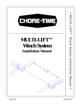
Item Description
1 Override switch: Used to directly drive the line(s)
up or down. (Located Inside the Unit)
2 Out of Limits Light: Indicates safety switches have
been activated.
3 Power Light
4 Time Clock: Indicates time of day and may be set
to automatically lower line(s) at a preset time.
5Power switch
6 Manual Up switch: Used to raise the line(s).
7 Manual Down switch: Used to manually lower the
line(s).
7 6 5
2 3
4
Figure 1.Winch Control
1054-4 8/14
1
View Inside Control
MF1054DAugust 2014

Winch Control Instruction
2
MF1054D
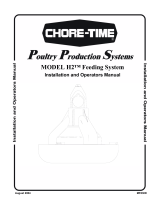
Time Clock Setting Instructions
Note: to save time you can set up each on/off cycle:
A) to be unique for each individual day, or
B) for Monday to Friday (days 1 to 5), or
C) for weekends only (days 6 & 7), or
D) for all days except Sunday (days 1 to 6), or …
E) the entire week at one time. This can save a lot of time when programming the “on” and “off” cycles.
Setting Current Time and Day
1.Slide the Set Switch to the left (Clock
Face).
2.Press the 1...7 Button until the arrow
points to the current day. Press the h (hour)
button and then the m (minute)
button to set the current time. The "PM"
indicator shows noon to 11:59 p.m.
3.Slide the Set Switch to "RUN".
The clock colon will blink between the
hours and minutes.
Setting Each Cycle to Switch On
1.slide the RUN switch to “ P ”. A “1“ indicates this is
the first switch cycle and a “bulb” icon indicates a
switch-on condition (circuit closes). (Hint: odd numbers indi-
cate a “switch-on” cycle.)
2.- press 1....7 button until arrows point to selected day(s) you want this ON cycle to occur. (See step 2
above for how to choose days of the week)
3.- press “ h ” and “ m ” buttons to show switch-on time, noting the “PM” indicator.
Set Switch
Hour Button
Minute
Button
AM/PM
Designation
Day
Arrow
Mode Switch
"P" Button
"1...7
Button
"R" Reset Button
Day Number
Figure 2.Winch Control
Skip
Button
Indicator
1st Switch Cycle
Bulb Icon

Winch Control Instruction
MF1054D
3
Setting Each Cycle to Switch Off
1.Slide the RUN switch to “ P ". Press the “p” button. Note that the switch cycle number
changes to 2 and the bulb blinks, indicating switch-off (circuit opens). (Hint: even numbers indi-
cate a “switch-off” cycle.)
2.- press 1...7 button until arrows point to the selected day(s) you want this OFF cycle to occur.
3.- press the h (hour) and m (minute) button to select-switch-off time.
Note: Remember you can repeat the above steps to program up to 8 on/off events for each day
of the week. By pressing the lower “ P “ button you can advance to the desired on/off
cycle. Slide RUN switch to RUN position. The clock colon will blink.
Auto Run Mode
1.Set time, Day, and desired switch cycles.
2.Slide the Set Switch to run and the Mode Switch to "Auto". Switching begins with
next "switch-on" time.
Override On
Slide the Mode Switch to I. The switch remains on indefinitely (circuit closed).
Override Off
Slide the Mode Switch to O. The switch remains off indefinitely (circuit open).
Skip Cycle
In Automatic run mode press the Skip button. The next program is skipped.
Setting Error
1.If EEE appears a setting error exists. The switch cycle number in error is shown. Slide the Set Switch
to "P".
2.Press the “ P “ button until "Cycle" is shown. Review and correct the error. Slide the Set Switch to
Run.
Clear Any Setting
1.Slide the Set Switch to "P". Press the "P" button to show any switch cycle to be cleared.
2.To Clear a switch cycle press the 1...7 button until no days are indicated.
3.Repeat for the next switch cycle. This on/off cycle is now inactive.
Clear All
To erase all settings press "R".

Winch Control Instruction
4
MF1054D
Winch Control Wiring Diagram with 29820-3 Tower Limit Switch
37215 MULTI-LIFT Winch with 34812 Winch Control
and 29820-3 Tower Limit Switch
or
14560 or 14580 Electric Power Winch with 34812 Winch Control
and 29820-3 Tower Limit Switch
Winch Control Wiring Diagram with 39464 Limit Switch
37215 MULTI-LIFT with 34812 Winch Control and 39464 Limit Switch
1054-4 8/14
1494-7 8/14

Winch Control Instruction
MF1054D
5
34812 Winch Control Parts Listing
Item Description Part No. Item Description Part No.
1 10 Amp Fuse 7350 10 Control Box Mount Panel 34852
2 Toggle Switch (DPDT) 46847 11 Momentary Switch 53064
3 Clear Lid 30859-1 12 Toggle Switch 6014
4 Control Box Latch 30862 13 Pilot Light 7044
5 Fuse Holder 24431 14 Winch Control Panel 34382
6 Relay 5574 15 Time Clock 51830
7 4 PDT Relay (230 V) 34910 16 Track Mounting Socket 34909
8 Terminal Mount Bracket 34563 17 Terminal Strip 34925
9 Control Box 34985 18 Control Box Latch Pivot 30863
2
2
13
12
14
11
9
8 17
716
6
51
3
4
10
15
18

Made to work.
Built to last.
®
Revisions to this Manual
Page No. Description of Change
-- Updated to digital Time Clock
Contact your nearby Chore-Time distributor or representative for additional parts and information.
Chore-Time Group
A division of CTB, Inc.
PO Box 2000
Milford, Indiana 46542-2000 USA
Phone (574) 658-4101 Fax (877) 730-8825
E-mail: www.choretimepoultry.com
Internet: poultr[email protected]
/