Maretron TMP100 Exhaust Gas Temperature Probe TP-EGT-1 User manual
- Category
- Networking
- Type
- User manual
This manual is also suitable for

Copyright © 2012 Maretron, LLP All Rights Reserved P/N: M002105 Rev.1.2 5/12
Installation Instructions
Maretron TP-EGT-1 TMP100 Exhaust Gas Temperature Probe
Instructions
Please follow these instructions to connect the TP-EGT-1 exhaust gas temperature probe to the NMEA 2000
®
network via a Maretron TMP100 Temperature Module. The wiring diagram appears in Figure 1 below. The
diagram shows a connection to channel #0, but connections to other channels are similar. Please note that the
TP-IP-1 may be connected only to channels #0 and #1. It may not be connected to channels #2, #3, #4, or #5.
1. The TP-EGT-1 is packaged with a compression fitting for mounting the temperature probe to an exhaust
manifold. Drill and tap a 1/8” NPT (27 threads per inch) hole in the manifold where you want the probe to
enter the manifold. Alternatively, you may drill a 13/64” hole in the manifold and weld on the supplied
adapter fitting, which has a 1/8” NPT hole. An existing hole on an exhaust manifold is somewhat
common. It may or may not be threaded 1/8” NPT. If is it not, you will need to either obtain a bushing to
adapt the existing hole in the manifold to 1/8” NPT or use a compression fitting that matches the existing
hole in the exhaust manifold.
2. Thread compression fitting into the threaded hole.
3. Insert the EGT probe into the compression fitting, and tighten the collar of the compression fitting to
achieve a snug, leak-proof fit.
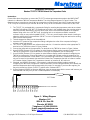
4. The TP-EGT-1 cable contains one yellow and one red wire. Connect the red wire to the appropriate Tx-
terminal on the TMP100 as shown in Figure 1 below.
5. Connect the yellow wire to the appropriate Tx+ terminal on the TMP100 as shown in Figure 1 below.
6. Use a DSM250 (firmware 1.3.8 or greater) or other Maretron display product capable of configuring the
TMP100 to configure the “Channel #x Source” to the type of temperature you are measuring.
7. Use a DSM250 (firmware 1.3.8 or greater) or other Maretron display product capable of configuring the
TMP100 to configure the “Channel #x Instance” to a number that is unique across the network for the
source you have selected. In other words, if you are measuring Exhaust Gas Temperature, there may be
only one channel on the network that measures Exhaust Gas Temperature that has an instance number
of 0. Number further Exhaust Gas Temperature channels as instance #1, #2, and so on.
8. If desired, use DSM250 (firmware 1.3.8 or greater) or other Maretron display product capable of
configuring the TMP100 to configure the “Channel #x Label” to a text string that allows you to identify the
particular temperature that is being measured by this probe. For example, if you have two engines, you
may wish to label one of them “Port EGT” and the other “Starboard EGT”.
9. Using a Maretron DSM250 or Maretron N2KView, show the temperature with the source and instance you
have selected and verify that you see a valid temperature on the display.
Maretron, LLP
9014 N. 23
rd
Ave #10
Phoenix, AZ 85021
Telephone: (+1) 866-550-9100
E-mail: [email protected]
Web: http://www.maretron.com
EGT Probe
1 2 5 4 3 6 7 8 9 10 11 12
T0+
T1-
TMP100 Screw Terminals
Yellow
T1+
T2+
T2-
T3+
T3-
T4+
T4-
T5+
T5-
Red
T0-
Figure 1 – Wiring Diagram
-
 1
1

Maretron TMP100 Exhaust Gas Temperature Probe TP-EGT-1 User manual
- Category
- Networking
- Type
- User manual
- This manual is also suitable for
Ask a question and I''ll find the answer in the document
Finding information in a document is now easier with AI