Page is loading ...

OWNER'S MANUAL
MODEL W1754
20" PLANER WITH
MOBILE BASE
Phone: (360) 734-3482 • Online Technical Support: tech-support@shopfox.biz
COPYRIGHT © APRIL, 2007 BY WOODSTOCK INTERNATIONAL, INC.
WARNING: NO PORTION OF THIS MANUAL MAY BE REPRODUCED IN ANY SHAPE OR FORM WITHOUT
THE WRITTEN APPROVAL OF WOODSTOCK INTERNATIONAL, INC.
Printed in China
#9093BL


SET UPELECTRICAL
MAINTENANCE
SERVICE
PARTS
OPERATIONSSAFETYINTRODUCTION
USE THE QUICK GUIDE PAGE LABELS TO SEARCH OUT INFORMATION FAST!
INTRODUCTION ...................................... 2
Woodstock Technical Support .................. 2
Machine Specifications ..........................
3
SAFETY ................................................ 5
Standard Safety Instructions ...................
5
Additional Safety Instructions for Planers ... 7
ELECTRICAL .......................................... 8
220V Operation ................................... 8
Electrical Specifications ........................
8
SETUP ................................................. 9
Unpacking ......................................... 9
Items Needed for Setup .........................
9
Inventory .......................................... 9
Machine Placement .............................
10
Lifting Planer ....................................
10
Cleaning Machine ................................11
Extension Wings .................................
12
Handwheel, Dust Hood & Caster ............13
Gearbox Oil Level ...............................
14
Connecting to Power ...........................
14
Test Run ..........................................
15
Recommended Adjustments ...................
16
Tighten V-Belts ..................................
16
OPERATIONS ........................................17
General ...........................................17
Basic Operation ..................................
17
Operation Tips ...................................
18
Feed Speed .......................................
19
Bed Rollers .......................................
20
ACCESSORIES ........................................21
Planer Accessories ..............................21
MAINTENANCE ......................................23
General ...........................................23
Cleaning ..........................................23
Maintenance Schedule ..........................
23
V-Belts ............................................24
Lubrication .......................................25
SERVICE ..............................................26
General ...........................................26
Inspecting Knives ................................
26
Setting/Replacing Knives ......................
27
Chain Tension ....................................
28
Table Parallelism ................................
29
Rollers, Breaker & Pressure Bar Heights ....
31
Spring Tension ...................................
34
Chip Deflector Positioning ....................
35
Scale Calibration ................................
35
Anti-Kickback Fingers ...........................
36
Pulley Alignment ................................
37
W1754 Electrical Components ................38
W1754 Wiring Diagram ........................39
Troubleshooting .................................40
Headstock Assembly Parts Breakdown .......
42
Headstock Assembly Parts
List ................43
Gearbox Parts Breakdown .....................45
Gearbox Parts List ..............................46
Base Breakdown .................................
47
Base Parts List ...................................
48
Table Breakdown & List ........................49
Columns Breakdown ............................50
Columns Parts List ..............................51
Labels & Cosmetic Parts .......................
52
Contents

-2-
W1754 20" Planer With Mobile Base
INTRODUCTION
Woodstock Technical Support
Your new SHOP FOX
®
20" Planer With Mobile Base has been specially designed to provide many years of
trouble-free service. Close attention to detail, ruggedly built parts and a rigid quality control program
assure safe and reliable operation.
Woodstock International, Inc. is committed to customer satisfaction. Our intent with this manual is to
include the basic information for safety, setup, operation, maintenance, and service of this product.
We stand behind our machines! In the event that questions arise about your machine, please contact
Woodstock International Technical Support at (360) 734-3482 or send e-mail to: tech-support@shopfox.
biz. Our knowledgeable staff will help you troubleshoot problems and process warranty claims.
INTRODUCTION
If you need the latest edition of this manual, you can download it from http://www.shopfox.biz.
If you have comments about this manual, please contact us at:
Woodstock International, Inc.
Attn: Technical Documentation Manager
P.O. Box 2309
Bellingham, WA 98227
Email: manuals@woodstockint.com

-3-
W1754 20" Planer With Mobile Base
INTRODUCTION

-4-
W1754 20" Planer With Mobile Base
INTRODUCTION
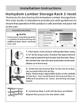
Controls and Features
A. Control Box and Panel
B. Return Rollers
C. Table Height Handwheel
D. Gearbox
E. Speed Control Knob
F. Table Height Scale
G. Table Locks
H. Lifting Bar
I. Front Access Panel
J. Foot Pedal
K. Extension Wing
L. Dust Hood
M. V-belt cover
N. Motor and Magnetic Switch Access
Panel
A
H
L
D
E
F
B
M
G
K
C
Figure 1. W1754 controls and features.
G
G
J
I
N

-5-
W1754 20" Planer With Mobile Base
SAFETY
SAFETY
READ MANUAL BEFORE OPERATING MACHINE.
FAILURE TO FOLLOW INSTRUCTIONS BELOW WILL
RESULT IN PERSONAL INJURY.
Standard Safety Instructions
1. READ THROUGH THE ENTIRE MANUAL BEFORE STARTING MACHINERY. Machinery presents serious
injury hazards to untrained users.
2. ALWAYS USE ANSI APPROVED SAFETY GLASSES WHEN OPERATING MACHINERY. Everyday eye-
glasses only have impact resistant lenses—they are NOT safety glasses.
3. ALWAYS WEAR AN NIOSH APPROVED RESPIRATOR WHEN OPERATING MACHINERY THAT PRODUCES
DUST. Wood dust is a carcinogen and can cause cancer and severe respiratory illnesses.
4. ALWAYS USE HEARING PROTECTION WHEN OPERATING MACHINERY. Machinery noise can cause
permanent hearing damage.
5. WEAR PROPER APPAREL. DO NOT wear loose clothing, gloves, neckties, rings, or jewelry which may
get caught in moving parts. Wear protective hair covering to contain long hair and wear non-slip
footwear.
6. NEVER OPERATE MACHINERY WHEN TIRED, OR UNDER THE INFLUENCE OF DRUGS OR ALCOHOL.
Be mentally alert at all times when running machinery.
7. ONLY ALLOW TRAINED AND PROPERLY SUPERVISED PERSONNEL TO OPERATE MACHINERY. Make
sure operation instructions are safe and clearly understood.
8. KEEP CHILDREN AND VISITORS AWAY. Keep all children and visitors a safe distance from the work
area.
9. MAKE WORKSHOP CHILD PROOF. Use padlocks, master switches, and remove start switch keys.
Indicates an imminently hazardous situation which, if not avoided, WILL
result in death or serious injury.
Indicates a potentially hazardous situation which, if not avoided, COULD
result in death or serious injury.
Indicates a potentially hazardous situation which, if not avoided, MAY
result in minor or moderate injury.
This symbol is used to alert the user to useful information about proper
operation of the equipment, and/or a situation that may cause damage
to the machinery.
NOTICE

-6-
W1754 20" Planer With Mobile Base
SAFETY
10. NEVER LEAVE WHEN MACHINE IS RUNNING. Turn power off and allow all moving parts to come to
a complete stop before leaving machine unattended.
11. DO NOT USE IN DANGEROUS ENVIRONMENTS. DO NOT use machinery in damp, wet locations, or
where any flammable or noxious fumes may exist.
12. KEEP WORK AREA CLEAN AND WELL LIT. Clutter and dark shadows may cause accidents.
13. USE A GROUNDED EXTENSION CORD RATED FOR THE MACHINE AMPERAGE. Undersized cords over-
heat and lose power. Replace extension cords if they become damaged
. DO NOT use extension cords
for 220V machinery.
14. ALWAYS DISCONNECT FROM POWER SOURCE BEFORE SERVICING MACHINERY. Make sure switch is
in OFF position before reconnecting.
15. MAINTAIN MACHINERY WITH CARE
. Keep blades sharp and clean for best and safest performance.
Follow instructions for lubricating and changing accessories.
16. MAKE SURE GUARDS ARE IN PLACE AND WORK CORRECTLY BEFORE USING MACHINERY.
17. REMOVE ADJUSTING KEYS AND WRENCHES. Make a habit of checking for keys and adjusting
wrenches before turning
machinery ON.
18. CHECK FOR DAMAGED PARTS BEFORE USING MACHINERY. Check for binding and alignment of
parts, broken parts, part mounting, loose bolts, and any other conditions that may affect machine
operation. Repair or replace damaged parts.
19. USE RECOMMENDED ACCESSORIES. Refer to the instruction manual for recommended accessories.
The use of improper accessories may cause risk of injury.
20. DO NOT FORCE MACHINERY. Work at the speed for which the machine or accessory was designed.
21. SECURE WORKPIECE. Use clamps or a vise to hold the workpiece when practical. A secured
workpiece protects your hands and frees both hands to operate the machine.
22. DO NOT OVERREACH. Keep proper footing and balance at all times.
23. MANY MACHINES WILL EJECT THE WORKPIECE TOWARD THE OPERATOR. Know and avoid condi-
tions that cause the workpiece to
"kickback."
24. ALWAYS LOCK MOBILE BASES BEFORE OPERATING MACHINERY.
25. BE AWARE THAT CERTAIN DUST MAY BE HAZARDOUS to the respiratory systems of people and
animals, especially fine dust. Make sure you know the hazards associated with the type of dust you
will be exposed to and always wear a respirator approved for that type of dust.

-7-
W1754 20" Planer With Mobile Base
SAFETY
Additional Safety Instructions for Planers
USE this and other machinery with caution
and respect. Always consider safety first,
as it applies to your individual working
conditions. No list of safety guidelines can
be complete—every shop environment is
different. Failure to follow guidelines could
result in serious personal injury, damage
to equipment or poor work results.
READ and understand this
entire instruction manual
before using this machine.
Serious personal injury
may occur if safety and
operational information is
not understood and fol
-
lowed. DO NOT risk your
safety by not reading!
1. INFEED CLEARANCE SAFETY: The infeed roller is designed to pull material into the cutterhead.
Always keep hands, clothing, and long hair away from the infeed roller during operation to pre
-
vent serious injury.
2. BODY POSITION WHILE OPERATING: The workpiece may kick out during operation. To avoid get-
ting hit, stand to the side of the planer during the entire operation.
3. PLANING CORRECT MATERIAL: Planing materials not designed for this planer creates a hazard for
yourself and the machine. Only plane natural wood stock with this planer. DO NOT plane MDF,
plywood, laminates, or other synthetic or man-made products.
4. GRAIN DIRECTION: Planing across the grain is hard on the planer and may cause the workpiece to
kick out. Always plane in the same direction or at a slight angle with the wood grain.
5. CLEAN STOCK: Only plane clean stock. Planing stock with nails, staples, or imbedded stone will
damage your cutters, and may cause a fire hazard if the dust collector captures sparks or hot par
-
ticles that have contacted the cutters. Always thoroughly inspect and prepare stock to avoid these
hazards.
6. MACHINE LIMITATIONS: The planer may kick out a workpiece at you or you can damage it if it is
pushed beyond these limits:
• Maximum Depth of Cut:
1
/8"
• Minimum Board Length: 8"
• Minimum Board Thickness:
3
/16"
• Maximum # of Boards at One Time: 1
7. LOOKING INSIDE PLANER: Wood chips fly around inside the planer at a high rate of speed. DO
NOT look inside the planer or remove guards/covers during operation.
8. REMOVING JAMMED WORKPIECES: Attempting to remove jammed workpieces while the planer is
running may cause serious injury to the operator. Always stop the planer and disconnect power
before removing jams.
9. DULL/DAMAGED CUTTERS: The planer may kick out a workpiece at the operator or give poor fin-
ish results if it is operated with dull or damaged cutters.
10. UNPLUGGING DURING ADJUSTMENTS: When connected to power, the planer can be accidentally
turned ON. Always disconnect power when servicing or adjusting the components of the planer.

-8-
W1754 20" Planer With Mobile Base
ELECTRICAL
ELECTRICAL
DO NOT work on your electrical system
if you are unsure about electrical
codes and wiring! Seek assistance from
a qualified electrician. Ignoring this
warning can cause electrocution, fire,
or machine damage.
220V Operation
The Model W1754 is wired for 220V single-phase opera-
tion.
This machine must be hardwired to a locking shutoff
switch by a qualified electrician. Since hardwiring involves
a permanent installation with conduit runs, this task can
only be safely accomplished by a qualified electrician. As
always, observe all applicable electrical codes when con
-
necting this machine to power.
This machine must be grounded! Verify the ground before
connecting this machine to the power source.
Electrical Specifications
Figure 2. Locking shutoff switch.
Voltage Amp Draw Min. Circuit Size Connection Cord Extension Cord
220V 30A 40A Hardwire Conduit Setup N/A (Hardwire Only)

-9-
W1754 20" Planer With Mobile Base
SET UP
The SHOP FOX
®
Model W1754 has been carefully pack-
aged for safe transporting. If you notice the machine has
been damaged, please contact your authorized SHOP
FOX
®
dealer immediately.
Unpacking
SETUP
The following is a description of the main components
shipped with the SHOP FOX
®
Model W1754. Lay the com-
ponents out to inventory them.
Note:
Some parts and hardware may already be installed
on the machine. Make sure to check the machine when
you use this inventory list.
Box Inventory (Figure
3) Qty
A. Planer Unit .................................................1
B. Dust Hood ...................................................1
C. Table Extension Wings ....................................2
D. Handwheel ..................................................1
E. Foot Lifting Lever .........................................1
F. Caster .......................................................1
G. Knife Gauge ................................................1
Inventory
If any parts are missing, examine the pack-
aging for the missing parts. For any missing
parts, find the part number in the back
of this manual and contact Woodstock
International, Inc. at (360) 734-3482 or at
SUFFOCATION HAZARD!
Immediately discard all
plastic bags and pack
-
ing materials to elimi
-
nate choking/suffocation
hazards for children and
animals.
Figure 3. Planer box inventory.
TURN OFF and LOCK your
master power switch so
power is not available
to the planer before
you do any assembly
or adjustment tasks. If
you ignore this warning
serious electrical shock
may occur, causing
injury or death!
OFF
The following items are needed, but not included, to set
up your machine:
• Safety Glasses (for each person) ........................1
• Solvent Cleaner ............................................1
• Shop Rags for Cleaning ....................... As Needed
• Extra Person for Lifting Help ............................
1
• Fork Lift .....................................................
1
• Straightedge (see
Page 12) ..............................1
• Phillips Screwdriver #2 ...................................
1
Items Needed for Setup
A
B
C
D
E
F
G

-10-
W1754 20" Planer With Mobile Base
SET UP
Figure 4. Example of planer being lifted
using forklift.
MAKE your shop “child safe." Ensure
that your workplace is inaccessible to
youngsters by closing and locking all
entrances when you are away. NEVER
allow untrained visitors in your shop
when assembling, adjusting or operat-
ing equipment.
The cabinet stand on the Model W1754 is equipped with
lifting bars to lift and place the planer.
Before lifting the planer, remove the shipping brace. We
recommend placing shop rags or cardboard between the
forks and cabinet base so you do not scratch the paint.
Figure
4 shows an example of a typical planer being lifted
correctly with a forklift by the lifting bars
.
• Floor Load: This machine distributes a heavy load in
a small footprint. Some floors may require additional
bracing to support both machine and operator.
• Working Clearances: Consider existing and
anticipated needs, size of material to be processed
through the machine, and space for auxiliary stands,
work tables or other machinery when establishing a
location for your planer
.
• Lighting: Lighting should be bright enough to
eliminate shadow and prevent eye strain.
Machine Placement
Lifting Planer
USE power lifting equipment to
lift this planer. Otherwise, seri
-
ous personal injury may occur.
Hardware and Tools (Not Shown)
• Hex Wrenches 3, 4, 5, 6mm .............................
4
• Wrenches 8/10, 12/14, 17/19mm ......................3
• Set Screws M8-1.25 x 20 (Wings) ........................6
• Hex Bolts M8-1.25 x 35 (Wings) .........................6
• Flat Washers 8mm (Wings) ...............................6
• Lock Washers 6mm (Wings) ..............................6
• Handwheel Bushing (Handwheel) .......................1
• Handwheel Handle (Handwheel) ........................1
• Hex Nut M12-1.75 (Handwheel) ........................ 1
• Flat Washer 12mm (Handwheel) ........................1
• Key 4 x 4 x 20mm (Handwheel) .........................1
• Flange Bolts M6-1 x 12 (Dust Hood) ....................6

-11-
W1754 20" Planer With Mobile Base
SET UP
Cleaning Machine
The table and other unpainted parts of your planer are
coated with a waxy grease that protects them from corro
-
sion during shipment. Clean this grease off with a solvent
cleaner or citrus-based degreaser. DO NOT use chlorine-
based solvents such as brake parts cleaner or acetone—if
you happen to splash some onto a painted surface, you
will ruin the finish.
These items are coated and must be cleaned:
1. Cutterhead
2. Table
3. Feed Rollers
4. Extension Wings and Wing Mounting Surfaces
NEVER use gasoline or other petroleum-
based solvents to clean with. Most have
low flash points, which make them
extremely flammable. A risk of explosion
and burning exists if these products are
used. Serious personal injury may occur
if this warning is ignored!
ALWAYS work in well-ventilated areas far from
possible ignition sources when using solvents to
clean machinery. Many solvents are toxic when
inhaled or ingested. Use care when disposing of
waste rags and towels to be sure they DO NOT create
fire or environmental hazards.

-12-
W1754 20" Planer With Mobile Base
SET UP
To attach the table extension wings, do these steps:
1. Install the M8-1.25 x 20 set screws in the holes in
the bottom of the wings
(Figure 5).
2. With the help of an assistant, attach the table
extension wings to the planer table (
Figure 5) with
the M8-1.25 x 35 hex bolts. Finger tighten the bolts
for now.
3. Check table-to-extension wing alignment (Figure
6) with a straightedge and adjust the leveling set
screws until the table and wings are flush.
4. Tighten the hex bolts.
Figure 5. Extension wing fasteners and
leveling controls.
Figure 6. Example of leveling extension
wings and table.
Extension Wings
Extension wings are heavy and could cause per-
sonal injury if dropped during installation. Have an
assistant hold the table while you fasten it to the
planer.
Set Screws
Hex Bolts

-13-
W1754 20" Planer With Mobile Base
SET UP
To install the handwheel, do these steps:
1. Place the bushing on the handwheel shaft.
2. Insert the 4 x 4 x 20 key into the shaft keyway.
3. Thread the handle into the handwheel.
4. Place the handwheel on the shaft and secure it with
the M12-1.75 hex nut and flat washer, as shown in
Figure 7.
Handwheel, Dust Hood &
Caster
Main Power
Switch
To install the dust hood, do these steps:
1. Put on gloves and adjust the gap between the edge
of the chip deflector and knife edge to
1
/4".
2. Attach the dust hood to the planer with six M6-1 x
12 flange bolts as shown in
Figure 8.
3. Attach the dust hood to the dust collector.
Note: To maximize work results and minimize clog-
ging, chipout, etc., use a dust collector with a mini
-
mum of 600 CFM at the planer dust port.
To install the caster and foot pedal, do these steps:
1. Remove the pin and hex bolt that are already mount-
ed in the foot pedal bracket.
2. Align the caster with the mounting holes in the foot
pedal bracket.
3. Insert the hex bolt removed in Step 1 into the hole
in the back side of the caster assembly, thread the
washer and locknut onto the bolt, and tighten the
bolt just enough for it to be snug without hampering
the pivot action of the caster.
During the next step, you MUST connect your
planer to a dust collection system. Accumulated
wood chips could cause a malfunction, resulting in
personal injury or damage to the planer.
Figure 7. Installing handwheel on shaft.
Figure 8. Dust hood attached.

-14-
W1754 20" Planer With Mobile Base
SET UP
Before starting your machine for the first time, make
sure the gearbox has oil. The proper oil level is just even
with the bottom of the fill plug hole. The gearbox uses
80W-90W automotive grade gear oil.
To check the gearbox oil level, do these steps:
1. Wipe the outside of the fill plug clean.
2. Using a 6mm hex wrench, remove the gearbox fill
plug (
Figure 10).
3. Using the short end of the hex wrench (make sure it
is CLEAN), dip it inside the fill hole and remove it.
(Do not drop the wrench into the gearbox!)
— If the end of the hex wrench is coated with oil,
then the gearbox oil level is okay. Replace the fill
plug and continue with set up.
— If the end of the hex wrench is not coated with
oil, then fill the gearbox with 80-90W gear oil
until the oil reaches the top of the fill plug.
Note:
Replace the gearbox oil after the first 20
hours of operation. This is a normal break-in pro
-
cedure. See Lubrication on Page 25.
Gearbox Oil Level
Figure 10. Gearbox fill plug location.
Connecting to Power
Make sure you have read and followed precautions listed
on Page
8, before connecting your planer to power. The
POWER button and STOP button
(Figure 11) should illumi-
nate when the planer is connected to the power. Refer to
Page 40 to troubleshoot any problems.
4. Mount the foot pedal onto the caster and insert the
pin between the two parts.
5. Lock the caster and pedal in place with the E-clip and
washers, as shown in
Figure 9.
�
Figure 9. Foot pedal and caster
assembled.
Foot Pedal
Caster
Pin
Bracket
Hex Bolt
Figure 11. W1754 control panel.

-15-
W1754 20" Planer With Mobile Base
SET UP
Test Run
Complete this test run process once you have familiarized
yourself with all instructions in this manual and taken all
safety precautions
. The purpose of the test run is to make
sure that the motor and EMERGENCY STOP button work
properly before proceeding.
To perform a test run, do these steps:
1. Read the entire manual, and make sure the gearbox
oil level is full (Refer to the
Lubrication section on
Page 25).
2. Make sure all tools and foreign objects have been
removed from the planer.
3. Make sure the feed control knob is pushed in or out
all the way (Refer to Feed Speed
, Page 19).
4. Put on safety glasses, and secure loose clothes or
long hair.
5. Press the green START button to turn the machine
ON (Figure 42). The START button should illuminate
and the planer should run smoothly with little or no
vibration.
— If you suspect any problems, immediately turn
the planer
OFF by pushing the red STOP button.
Refer to
Page 40 to troubleshoot/fix any problems
before starting the planer again.
— If the source of an unusual noise or vibration is not
readily apparent, contact our technical support
for help at (360) 734-3482 or contact us online at
6. Press the STOP button in.
7. Press the START button in. The machine should not
run and the START button should not illuminate.
— If the STOP button is working correctly, turn it
clockwise until it pops out. The machine is ready
for operation.
—If the planer starts, the STOP button is not working
correctly. Immediately DISCONNECT THE PLANER
FROM POWER! and contact our technical support
before proceeding further.

-16-
W1754 20" Planer With Mobile Base
SET UP
Loose hair and clothing could get
caught in machinery and cause serious
personal injury. Keep loose clothing
rolled up and long hair tied up and
away from machinery.
Tighten V-Belts
The final step in the setup process must be done after
approximately 16 hours of operation. During this first 16
hours, the V-belts will stretch and seat into the pulley
grooves. After this 16 hours, the V-belts must be ten
-
sioned or your belts will slip and burn out. Refer to Page
24
when you are ready to perform this important adjust-
ment.
Note:
Pulleys and belts run very hot. This is a normal
condition. Allow them to cool before making adjustments.
Note
: A collection of black belt dust at the bottom of the
belt housing is a normal during the life of the machine
and does not indicate premature belt failure is in prog
-
ress.
For your convenience, the adjustments listed below have
been performed at the factory and no further setup is
required to operate your machine.
However, because of the many variables involved with
shipping and storage, some of these adjustments may
need to be repeated to ensure optimum cutting results.
Keep this in mind as you start to use your new planer.
Step-by-step instructions for these adjustments can be
found in the SERVICE section.
1. Table Parallelism (Page 29).
2. Chain Tension (Page 28).
3. Spring Tension (Page 34).
4. Rollers, Chip Breakers and Pressure Bar Heights
(Page 31).
5. Chip Deflector Positioning (Page 35).
Recommended
Adjustments

-17-
W1754 20" Planer With Mobile Base
OPERATIONS
OPERATIONS
General
The Model W1754 will perform many types of operations
that are beyond the scope of this manual. Many of these
operations can be dangerous or deadly if performed incor
-
rectly.
The instructions in this section are written with the under
-
standing that the operator has the necessary knowledge
and skills to operate this machine. If at any time you are
experiencing difficulties performing any operation, stop
using the machine!
If you are an inexperienced operator, we strongly recom
-
mend that you read books, trade articles, or seek training
from an experienced
planer operator before performing
any unfamiliar operations. Above all, your safety should
come first!
READ and understand this entire instruc-
tion manual before using this machine.
Serious personal injury may occur if
safety and operational information is not
understood and followed. DO NOT risk
your safety by not reading!
The table moves approximately
1
/16" with one turn of the
handwheel.
The basic steps of operating the planer are as follows:
1. Put on safety glasses, respirator, and hearing protec-
tion.
2. Unless your workpiece is very flat, surface plane
one face of the workpiece on a jointer until it is
flat—having the face flat will ensure that it sits flat
on the planer table during operation.
3. Adjust the table height slightly lower than your
workpiece to ensure the first cut is as light as pos
-
sible (approximately
1
/32"–
1
/16"). This cut removes any
excessive high spots.
4. Start the planer.
5. Making sure not to stand directly in front or behind
the workpiece to avoid kickback injury, place the
flat side of the board down on the table, and feed
the workpiece through the planer.
— If the cut is too heavy and bogs down the planer,
turn the planer
OFF immediately, allow it to come
to a complete stop, and remove the workpiece.
Lower the table, then repeat Steps 2–5
.
Basic Operation
DO NOT investigate problems or adjust
the planer while it is running. Wait
until the machine is turned
OFF and
all working parts have come to a
complete stop before proceeding!
Damage to your eyes, lungs, and ears
could result from using this machine
without proper protective gear. Always
wear safety glasses, a respirator, and
hearing protection when operating this
machine.
OFF

-18-
W1754 20" Planer With Mobile Base
OPERATIONS
6. Measure your workpiece thickness and adjust the
table height as necessary to take a lighter or heavier
pass, depending on your needs. For most wood
types,
1
/16" per pass is a good cutting depth.
Note: Any time you switch directions with the
handwheel, there will be a small amount of back
-
lash—so the first crank of the handwheel after
switching directions will be slightly less than
1
/16".
However, as long as you move the handwheel in the
same direction during operation, backlash will not
be a factor.
• Inspect lumber for defects, warping, cupping, twist-
ing, and for foreign objects such as nails, staples,
and imbedded gravel, which, if they hit the cutters
and are drawn into the dust collector, may cause a
fire hazard. If you have any question about the qual
-
ity of your lumber, do not use it. Remember, wood
stacked on a concrete floor can have small pieces of
stone or concrete pressed into the surface.
• Use the full width of the planer. Alternate between
the left, the right, and the middle when feeding lum
-
ber into the planer. Your cutters will remain sharp
much longer.
• Scrape all glue off of joined boards before planing.
• Plane ONLY natural wood fiber. No wood composites
(OSB, MDF, particle board, etc.).
• Plane wood with the grain. Never feed end-cut or
end-grained lumber into your planer.
• Do not use boards with loose or large knots, splits,
crossgrain or other obvious blemishes or defects. They
can damage the machine and pose the possibility of
operator injury.
• Keep your work area clear.
• When making multiple passes through the planer on
long stock, use the stock return rollers on the top of
the machine to move the material back to the infeed
side of the machine.
• Avoid planing wood with a high water content. Wood
with more than 20% moisture content or wood exposed
to rain or snow, will plane poorly and cause excessive
wear to the cutters and motor. Excess moisture can
also hasten rust and corrosion.
Operation Tips
/