Patton electronic 4400 User manual
- Category
- Gateways/controllers
- Type
- User manual

SmartNode 4400
IpChannel Bank
Getting Started Guide
Sales Office:
+1 (301) 975-1000
Technical Support:
+1 (301) 975-1007
E-mail:
WWW:
www.patton.com
Part Number:
07MSN4400-GS, Rev. A
Revised:
October 8, 2009
Important
This is a Class A device and is intended for use in a light industrial environment. It is not intended nor approved for use in an industrial
or residential environment.
Start Installation
For Quick

Patton Electronics Company, Inc.
7622 Rickenbacker Drive
Gaithersburg, MD 20879 USA
Tel: +1 (301) 975-1000
Fax: +1 (301) 869-9293
Support: +1 (301) 975-1007
Web: www.patton.com
E-mail: [email protected]
Trademark Statement
The terms
SmartNode
,
SmartWare
, and
SmartView
are trademarks of Patton
Electronics Company. All other trademarks presented in this document are the prop-
erty of their respective owners.
Copyright © 2009, Patton Electronics Company. All rights reserved.
The information in this document is subject to change without notice. Patton Elec-
tronics assumes no liability for errors that may appear in this document.
Important Information
To use virtual private network (VPN) and/or AES/DES/3DES encryption capabilities
with the SmartNode 4400, you may need to purchase additional licenses, hardware,
software, network connection, and/or service. Contact
or
+1 (301) 975-1000
for assistance.
Warranty Information
The software described in this document is furnished under a license and may be used
or copied only in accordance with the terms of such license. For information about the
license, see Appendix E, "End user license agreement" on page 63 or go to
www.patton.com
.
Patton Electronics warrants all SmartNode router components to be free from defects,
and will—at our option—repair or replace the product should it fail within one year
from the first date of the shipment.
This warranty is limited to defects in workmanship or materials, and does not cover
customer damage, abuse or unauthorized modification. If the product fails to perform
as warranted, your sole recourse shall be repair or replacement as described above.
Under no condition shall Patton Electronics be liable for any damages incurred by the
use of this product. These damages include, but are not limited to, the following: lost
profits, lost savings and incidental or consequential damages arising from the use of or
inability to use this product. Patton Electronics specifically disclaims all other warran-
ties, expressed or implied, and the installation or use of this product shall be deemed
an acceptance of these terms by the user.

3
Summary Table of Contents
1 General information...................................................................................................................................... 14
2 Applications overview.................................................................................................................................... 20
3 Hardware installation.................................................................................................................................... 23
4 Getting started with the SmartNode 4400 Series........................................................................................... 34
5 Contacting Patton for assistance ................................................................................................................... 44
A Compliance information .............................................................................................................................. 47
B Specifications ................................................................................................................................................ 49
C Port pin-outs ................................................................................................................................................ 55
D Factory Configuration .................................................................................................................................. 61
E End user license agreement ........................................................................................................................... 63
F Installation checklist .................................................................................................................................... 66
G Accessories .................................................................................................................................................... 68

4
Table of Contents
Summary Table of Contents ........................................................................................................................... 3
Table of Contents ........................................................................................................................................... 4
List of Figures ................................................................................................................................................. 7
List of Tables .................................................................................................................................................. 8
About this guide ............................................................................................................................................. 9
Audience................................................................................................................................................................. 9
Structure................................................................................................................................................................. 9
Precautions ............................................................................................................................................................. 9
Safety when working with electricity
.......................................................................................................................................................................11
Preventing Electrostatic Discharge Damage ....................................................................................................12
General observations .......................................................................................................................................12
Typographical conventions used in this document................................................................................................ 13
General conventions .......................................................................................................................................13
1 General information...................................................................................................................................... 14
SmartNode 4400 Series overview...........................................................................................................................15
SmartNode 4400 Series detailed description..........................................................................................................16
SmartNode 4400 Series front panel ................................................................................................................17
SmartNode 4400 Series rear panels .................................................................................................................18
Reset button behavior ...............................................................................................................................19
2 Applications overview.................................................................................................................................... 20
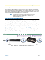
Introduction..........................................................................................................................................................21
SmartNode 4400 Series applications......................................................................................................................21
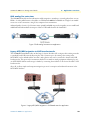
Enterprise FXS concentration and extension over IP and T1/E1 .....................................................................21
Bulk analog line extensions .............................................................................................................................22
Legacy MTU/MDU migration to VoIP based networks .................................................................................22
3 Hardware installation.................................................................................................................................... 23
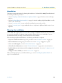
Introduction..........................................................................................................................................................24
Planning the installation........................................................................................................................................24
Installation checklist ........................................................................................................................................25
Site log ............................................................................................................................................................25
Network information ......................................................................................................................................26
Network diagram ......................................................................................................................................26
IP related information ...............................................................................................................................26
Configuration tools .........................................................................................................................................26
AC Power Mains .............................................................................................................................................26
Location and mounting requirements .............................................................................................................27
Installing the IpChannel Bank...............................................................................................................................27
Unpacking the Model SN4400 series IpChannel Bank ...................................................................................27
IpChannel Bank chassis installation ................................................................................................................27

5
SmartNode 4400 Series Getting Started Guide
Table of Contents
Connecting cables ...........................................................................................................................................28
Connecting the FXS ports .........................................................................................................................28
Connecting the Ethernet ports ..................................................................................................................28
Connecting the 10/100Base-T Ethernet ports to an Ethernet switch or hub .......................................29
Connecting a 10/100Base-T Ethernet port to an Ethernet-capable workstation ..................................29
Connecting the EIA-561 RS-232 configuration port (DCE configured) ...................................................30
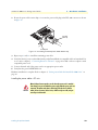
Connecting power ...........................................................................................................................................30
Grounding the Model SN4400—AC and DC units .................................................................................30
Installing the power cables—AC units .......................................................................................................31
Installing the power cables—DC units ......................................................................................................32
4 Getting started with the SmartNode 4400 Series........................................................................................... 34
Introduction..........................................................................................................................................................35
1. Configure IP address .........................................................................................................................................36
Factory-default IP settings ...............................................................................................................................36
Connect to the RS-232 console port ...............................................................................................................37
Login ..............................................................................................................................................................38
Changing the WAN IP address .......................................................................................................................38
2. Connecting the SmartNode to the network .......................................................................................................39
3. Loading the configuration (optional).................................................................................................................39
Bootloader.............................................................................................................................................................40
Start Bootloader ..............................................................................................................................................40
Start-up with factory configuration .................................................................................................................41
Load a new application image (SmartWare) via TFTP ....................................................................................41
Load a new application image (SmartWare) via the serial link .........................................................................43
Additional information..........................................................................................................................................43
5 Contacting Patton for assistance ................................................................................................................... 44
Introduction..........................................................................................................................................................45
Contact information..............................................................................................................................................45
Warranty Service and Returned Merchandise Authorizations (RMAs)...................................................................45
Warranty coverage ..........................................................................................................................................45
Out-of-warranty service .............................................................................................................................46
Returns for credit ......................................................................................................................................46
Return for credit policy .............................................................................................................................46
RMA numbers ................................................................................................................................................46
Shipping instructions ................................................................................................................................46
A Compliance information .............................................................................................................................. 47
Compliance ...........................................................................................................................................................48
EMC compliance: ...........................................................................................................................................48
Safety compliance: ..........................................................................................................................................48
CE Declaration of Conformity ..............................................................................................................................48
Authorized European Representative .....................................................................................................................48
B Specifications ................................................................................................................................................ 49

6
SmartNode 4400 Series Getting Started Guide
Table of Contents
Voice connectivity - FXS .......................................................................................................................................50
Ethernet interface ..................................................................................................................................................50
Console port..........................................................................................................................................................50
FXS ports ..............................................................................................................................................................50
PPP and Frame-Relay support ...............................................................................................................................50
Voice processing (signaling dependent)..................................................................................................................50
Fax and modem support........................................................................................................................................51
Voice signaling ......................................................................................................................................................51
Voice routing-session router ..................................................................................................................................52
IP services..............................................................................................................................................................52
Management .........................................................................................................................................................52
Operating environment .........................................................................................................................................52
Temperature ...................................................................................................................................................52
Humidity ........................................................................................................................................................52
Altitude ...........................................................................................................................................................53
System...................................................................................................................................................................53
Dimensions ...........................................................................................................................................................53
Weight and power dissipation ...............................................................................................................................53
Power supply .........................................................................................................................................................53
Universal AC version ......................................................................................................................................53
DC version .....................................................................................................................................................53
Identification of the SmartNode devices via SNMP...............................................................................................54
C Port pin-outs ................................................................................................................................................ 55
Introduction..........................................................................................................................................................56
Console port..........................................................................................................................................................56
Ethernet 10Base-T and 100Base-T port.................................................................................................................56
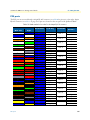
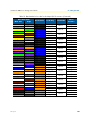
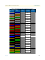
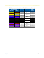
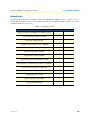
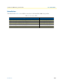
FXS ports ..............................................................................................................................................................57
D Factory Configuration .................................................................................................................................. 61
Introduction..........................................................................................................................................................62
E End user license agreement ........................................................................................................................... 63
End User License Agreement .................................................................................................................................64
1. Definitions ..................................................................................................................................................64
2. Title ............................................................................................................................................................64
3. Term ...........................................................................................................................................................64
4. Grant of License ..........................................................................................................................................64
5. Warranty ....................................................................................................................................................64
6. Termination ................................................................................................................................................65
7. Other licenses .............................................................................................................................................65
F Installation checklist .................................................................................................................................... 66
Introduction..........................................................................................................................................................67
G Accessories .................................................................................................................................................... 68
Introduction..........................................................................................................................................................69

7
List of Figures
1 Model SN4432 IpChannel Bank . . . . . . . . . . . . . . . . . . . . . . . . . . . . . . . . . . . . . . . . . . . . . . . . . . . . . . . . . . . 15
2 Model SN4432 IpChannel Bank front panel LEDs. . . . . . . . . . . . . . . . . . . . . . . . . . . . . . . . . . . . . . . . . . . . . . 17
3 SmartNode 4400 rear panels . . . . . . . . . . . . . . . . . . . . . . . . . . . . . . . . . . . . . . . . . . . . . . . . . . . . . . . . . . . . . . . 18
4 Enterprise FXS concentration and extension over IP and T1/E1 . . . . . . . . . . . . . . . . . . . . . . . . . . . . . . . . . . . . 21
5 Bulk analog line extensions application . . . . . . . . . . . . . . . . . . . . . . . . . . . . . . . . . . . . . . . . . . . . . . . . . . . . . . . 22
6 Legacy MTU/MDU migration to VoIP-based networks application . . . . . . . . . . . . . . . . . . . . . . . . . . . . . . . . . 22
7 Model SN4400 Ethernet port . . . . . . . . . . . . . . . . . . . . . . . . . . . . . . . . . . . . . . . . . . . . . . . . . . . . . . . . . . . . . . 29
8 Straight-through RJ-45-to-RJ-45 Ethernet cable diagram . . . . . . . . . . . . . . . . . . . . . . . . . . . . . . . . . . . . . . . . . 29
9 Cross-over RJ-45-to-RJ-45 Ethernet cable diagram . . . . . . . . . . . . . . . . . . . . . . . . . . . . . . . . . . . . . . . . . . . . . . 29
10 DB-9-to-RJ-45 cable diagram . . . . . . . . . . . . . . . . . . . . . . . . . . . . . . . . . . . . . . . . . . . . . . . . . . . . . . . . . . . . . . 30
11 IEC-320 connector and grounding stud locations . . . . . . . . . . . . . . . . . . . . . . . . . . . . . . . . . . . . . . . . . . . . . . . 31
12 Grounding stud and power cable retainer clip . . . . . . . . . . . . . . . . . . . . . . . . . . . . . . . . . . . . . . . . . . . . . . . . . . 32
13 DC connector, -DC and +DC input view . . . . . . . . . . . . . . . . . . . . . . . . . . . . . . . . . . . . . . . . . . . . . . . . . . . . . 33
14 Connecting the SmartNode to your laptop PC . . . . . . . . . . . . . . . . . . . . . . . . . . . . . . . . . . . . . . . . . . . . . . . . . 35
15 Connecting the SmartNode to the network . . . . . . . . . . . . . . . . . . . . . . . . . . . . . . . . . . . . . . . . . . . . . . . . . . . 35
16 Loading the configuration . . . . . . . . . . . . . . . . . . . . . . . . . . . . . . . . . . . . . . . . . . . . . . . . . . . . . . . . . . . . . . . . . 36
17 Connecting to the RS-232 Console port . . . . . . . . . . . . . . . . . . . . . . . . . . . . . . . . . . . . . . . . . . . . . . . . . . . . . . 37
18 Connecting the SmartNode to the network . . . . . . . . . . . . . . . . . . . . . . . . . . . . . . . . . . . . . . . . . . . . . . . . . . . 39
19 EIA-561 (RJ-45 8-pin) port . . . . . . . . . . . . . . . . . . . . . . . . . . . . . . . . . . . . . . . . . . . . . . . . . . . . . . . . . . . . . . . 56
20 Model SN4400 Ethernet port . . . . . . . . . . . . . . . . . . . . . . . . . . . . . . . . . . . . . . . . . . . . . . . . . . . . . . . . . . . . . . 56

8
List of Tables
1 General conventions . . . . . . . . . . . . . . . . . . . . . . . . . . . . . . . . . . . . . . . . . . . . . . . . . . . . . . . . . . . . . . . . . . . . . 13
2 Front panel LEDs . . . . . . . . . . . . . . . . . . . . . . . . . . . . . . . . . . . . . . . . . . . . . . . . . . . . . . . . . . . . . . . . . . . . . . . 17
3 Port descriptions . . . . . . . . . . . . . . . . . . . . . . . . . . . . . . . . . . . . . . . . . . . . . . . . . . . . . . . . . . . . . . . . . . . . . . . . 18
4 Installation checklist . . . . . . . . . . . . . . . . . . . . . . . . . . . . . . . . . . . . . . . . . . . . . . . . . . . . . . . . . . . . . . . . . . . . . 25
5 Sample site log entries . . . . . . . . . . . . . . . . . . . . . . . . . . . . . . . . . . . . . . . . . . . . . . . . . . . . . . . . . . . . . . . . . . . . 25
6 IP addresses/subnets for SN4400 . . . . . . . . . . . . . . . . . . . . . . . . . . . . . . . . . . . . . . . . . . . . . . . . . . . . . . . . . . . 26
7 Factory default IP address and network mask configuration . . . . . . . . . . . . . . . . . . . . . . . . . . . . . . . . . . . . . . . 36
8 SmartNode weight and maximum power specifications . . . . . . . . . . . . . . . . . . . . . . . . . . . . . . . . . . . . . . . . . . 53
9 SmartNode Models and their Unique sysObjectID . . . . . . . . . . . . . . . . . . . . . . . . . . . . . . . . . . . . . . . . . . . . . . 54
10 Band marked color-codes for the 64-pin RJ-21X connector . . . . . . . . . . . . . . . . . . . . . . . . . . . . . . . . . . . . . . . 57
11 Band marked color-codes for the 50-pin RJ-21X connector . . . . . . . . . . . . . . . . . . . . . . . . . . . . . . . . . . . . . . . 59
12 Installation checklist . . . . . . . . . . . . . . . . . . . . . . . . . . . . . . . . . . . . . . . . . . . . . . . . . . . . . . . . . . . . . . . . . . . . . 67
13 Accessory cables . . . . . . . . . . . . . . . . . . . . . . . . . . . . . . . . . . . . . . . . . . . . . . . . . . . . . . . . . . . . . . . . . . . . . . . . 69

9
About this guide
This guide describes the SmartNode 4400 Series IpChannel Bank hardware, installation and basic configura-
tion. For detailed software configuration information refer to the
SmartWare Software Configuration Guide
and
the available Configuration Notes.
Audience
This guide is intended for the following users:
• Operators
• Installers
• Maintenance technicians
Structure
This guide contains the following chapters and appendices:
• Chapter 1, “General information” on page 14 provides information about router features and capabilities
• Chapter 2, “Applications overview” on page 20 contains an overview describing router operation
and applications
• Chapter 3, “Hardware installation” on page 23 provides quick start hardware installation procedures
• Chapter 4, “Getting started with the SmartNode 4400 Series” on page 34 describes getting started with the
SmartNode IpChannel Bank
• Chapter 5, “Contacting Patton for assistance” on page 44 contains information on contacting Patton tech-
nical support for assistance
• Appendix A, “Compliance information” on page 47 contains compliance information for the SmartNode
• Appendix B, “Specifications” on page 49 contains for the specifications for the IpChannel Bank
• Appendix C, “Port pin-outs” on page 55 provides cable pinouts for the various interface ports
• Appendix D, “Factory Configuration” on page 61 lists the factory configuration settings for the SmartNode
4400 Series devices
• Appendix E, “End user license agreement” on page 63 provides detailed information on the EULA
• Appendix F, “Installation checklist” on page 66 lists the tasks for installing the SmartNode 4400 IP
Channel Bank
For best results, read the contents of this guide before you install the IpChannel Bank.
Precautions
Notes, cautions, and warnings, which have the following meanings, are used throughout this guide to help you
become aware of potential problems.
Warnings
are intended to prevent safety hazards that could result in per-
sonal injury.
Cautions
are intended to prevent situations that could result in property damage or
impaired functioning.

10
SmartNode 4400 Series Getting Started Guide
About this guide
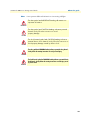
Note
A note presents additional information or interesting sidelights.
The alert symbol and IMPORTANT heading calls attention to
important information.
The alert symbol and CAUTION heading indicate a potential
hazard. Strictly follow the instructions to avoid
property damage.
The shock hazard symbol and CAUTION heading indicate a
potential electric shock hazard. Strictly follow the instructions to
avoid property damage caused by electric shock.
The alert symbol and WARNING heading indicate a potential safety hazard.
Strictly follow the warning instructions to avoid personal injury.
The shock hazard symbol and WARNING heading indicate a potential electric
shock hazard. Strictly follow the warning instructions to avoid injury caused
by electric shock.
IMPORTANT
CAUTION
CAUTION
WARNING
WARNING

11
SmartNode 4400 Series Getting Started Guide
About this guide
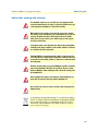
Safety when working with electricity
The SmartNode contains no user serviceable parts. The equipment shall be
returned to Patton Electronics for repairs, or repaired by qualified service per-
sonnel. Opening the SmartNode case will void the warranty.
Mains Voltage: Do not open the case the when the power cord is attached.
Line voltages are present within the power supply when the power cords are
connected. The mains outlet that is utilized to power the device shall be
within 10 feet (3 meters) of the device, shall be easily accessible, and pro-
tected by a circuit breaker.
For AC powered units, ensure that the power cable used meets all applicable
standards for the country in which it is to be installed, and that it is connected
to a wall outlet which has earth ground.
The Model SN4400 is not shipped with power cables. For AC powered units,
ensure that the power cable used meets all applicable standards for the coun-
try in which it is to be installed, and that it is connected to a wall outlet which
has earth ground.
Hazardous network voltages are present in WAN ports regardless of whether
power to the SmartNode is ON or OFF. To avoid electric shock, use caution
when near WAN ports. When detaching the cables, detach the end away from
the SmartNode first.
Because telephone line voltages can be dangerous, when detaching the net-
work cables, disconnect the end away from the SmartNode first.
Do not work on the system or connect or disconnect cables during periods of
lightning activity.
In accordance with the requirements of council directive 2002/
96/EC on Waste of Electrical and Electronic Equipment (WEEE),
ensure that at end-of-life you separate this product from other
waste and scrap and deliver to the WEEE collection system in
your country for recycling.
WARNING
WARNING
WARNING
WARNING
WARNING
WARNING
WARNING

12
SmartNode 4400 Series Getting Started Guide
About this guide
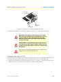
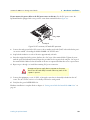
Preventing Electrostatic Discharge Damage
When starting to install interface cards place the interface card on its shielded plastic bag if you lay it on
your bench.
Electrostatic Discharge (ESD) can damage equipment and impair electrical circuitry. It occurs when electronic
printed circuit cards are improperly handled and can result in complete or intermittent failures.
General observations
• C
lean the case with a soft slightly moist anti-static cloth
• Place the unit on a flat surface and ensure free air circulation
• Avoid exposing the unit to direct sunlight and other heat sources
•
Protect the unit from moisture, vapors, and corrosive liquid
s
Always follow ESD prevention procedures when removing and
replacing cards.
Wear an ESD-preventive wrist strap, ensuring that it makes good
skin contact. Connect the clip to an unpainted surface of the
chassis frame to safely channel unwanted ESD voltages
to ground.
To properly guard against ESD damage and shocks, the wrist
strap and cord must operate effectively. If no wrist strap is avail-
able, ground yourself by touching the metal part of the chassis.
CAUTION

13
SmartNode 4400 Series Getting Started Guide
About this guide
Typographical conventions used in this document
This section describes the typographical conventions and terms used in this guide.
General conventions
The procedures described in this manual use the following text conventions:
Table 1. General conventions
Convention Meaning
Garamond blue type
Indicates a cross-reference hyperlink that points to a figure, graphic, table, or sec-
tion heading. Clicking on the hyperlink jumps you to the reference. When you
have finished reviewing the reference, click on the
Go to Previous View
button in the Adobe® Acrobat® Reader toolbar to return to your starting point.
Futura bold type Commands and keywords are in
boldface
font.
Futura bold-italic type Parts of commands, which are related to elements already named by the user, are
in
boldface italic
font.
Italicized Futura type
Variables for which you supply values are in
italic
font
Futura type
Indicates the names of fields or windows.
Garamond bold type Indicates the names of command buttons that execute an action.
< >
Angle brackets indicate function and keyboard keys, such as <SHIFT>, <CTRL>,
<C>, and so on.
[ ] Elements in square brackets are optional.
{a | b | c} Alternative but required keywords are grouped in braces ({ }) and are separated
by vertical bars ( | )
blue screen Information you enter is in
blue screen
font.
screen Terminal sessions and information the system displays are in
screen font
.
node The leading IP address or nodename of a SmartNode is substituted with
node
in
boldface italic
font.
SN The leading
SN
on a command line represents the nodename of the SmartNode
# An hash sign at the beginning of a line indicates a comment line.

14
Chapter 1
General information
Chapter contents
SmartNode 4400 Series overview...........................................................................................................................15
SmartNode 4400 Series detailed description..........................................................................................................16
SmartNode 4400 Series front panel ................................................................................................................17
SmartNode 4400 Series rear panels .................................................................................................................18
Reset button behavior ...............................................................................................................................19

SmartNode 4400 Series overview
15
SmartNode 4400 Series Getting Started Guide
1 • General information
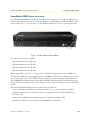
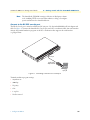
SmartNode 4400 Series overview
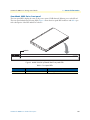
The IpChannel Bank 4400 Series are Analog Access Routers that support 12 to 32 VoIP calls. Filling the gap
between small media gateways and T1/E1 gateway equipment, the SN4400 Series IpChannel Bank fits your
needs cost effectively—so you won’t have to “stack” multiple smaller units or buy an over-designed product.
Figure 1. Model SN4432 IpChannel Bank
The following base models are available:
• IpChannel Bank 4412 (12 VoIP calls)
• IpChannel Bank 4416 (16 VoIP calls)
• IpChannel Bank 4424 (24 VoIP calls)
• IpChannel Bank 4432 (32 VoIP calls)
Refer to appendix B, “Specifications” on page 49 for a complete feature description of the SN4400 Series.
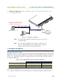
The SmartNode 4400 Series comes equipped with two 10/100Base-T Ethernet ports and from 12 to 32 FXS
ports. This provides voice-over-IP (VoIP) and Internet telephony integrated with routed serial-WAN access.
The SN4400 IpChannel Bank supports Frame-Relay and PPP networking with VPN and firewall functions
and provides extensive quality of service (QoS) features for best-possible voice quality over any broadband IP
network.
The SmartNode IpChannel Bank performs the following major functions:
• Voice over IP and local switching via a combination of 12, 16, 24, or 32 analog phone ports (FXS).
• Standards-compliant conversion between analog voice and digital VoIP in accordance with SIP and
H.323 protocols.
• Internet access and IP Routing with IP QoS support for mixed voice and data traffic.
• Routed LAN-to-WAN connectivity between two 10/100 Ethernet LAN ports

SmartNode 4400 Series detailed description
16
SmartNode 4400 Series Getting Started Guide
1 • General information
SmartNode 4400 Series detailed description
The SmartNode 4400 Series IpChannel Bank provides VoIP calling from 12 to 32 analog phone lines. Inte-
grated within the IpChannel Bank are 2 Ethernet ports, one for LAN, the other for WAN connectivity. The
front panel contains LED indicators for system status-at-a-glance, and the rear panel provides connectivity for
the FXS analog ports, the ENET ports, a WAN port, and an RS-232 control port.
Each model in the SN4400 series comes equipped with two 10/100Base-T Ethernet ports. Ethernet port
ETH0/1
is commonly used for the LAN connection.
ETH0/0
can be used for WAN access or as a second LAN
connection. The following base model numbers are available:
• SN4412/JS/UI (12 FXS ports, UI power supply)
• SN4416/JS/UI (16 FXS ports, UI power supply)
• SN4424/JS/UI (24 FXS ports, UI power supply)
• SN4432/JS/UI (32 FXS ports, UI power supply)
• SN4412/JS/48 (12 FXS ports, 48V DC power supply)
• SN4416/JS/48 (16 FXS ports, 48V DC power supply)
• SN4424/JS/48 (24 FXS ports, 48V DC power supply)
• SN4432/JS/48 (32 FXS ports, 48V DC power supply)
Note The model-code suffixes indicate the following features according to
the following conventions:
• JS indicates FXS ports are present
• UI indicates universal input (UI) power supply
• 48 indicates internal 48V DC power supply

SmartNode 4400 Series detailed description 17
SmartNode 4400 Series Getting Started Guide 1 • General information
SmartNode 4400 Series front panel
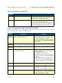
The front panel LEDs display the status of the power, system, VOIP channels, Ethernet ports, and call load.
The front panel includes the following LEDs. Figure 2 shows the front panel LED indicators and table 2 pro-
vides a description of the LED indicators’ behavior.
Figure 2. Model SN4432 IpChannel Bank front panel LEDs.
Table 2. Front panel LEDs
LED LED Condition Description
Power Solid Green Power is applied
UNIT EQUIPPED WITH DUAL SU
PPLIES
DISCONNECT BOTH SUPPLIES
BEFORE SERVICING
POWER
IPChannelBank
SmartNode 4400 VoIP IAD
POWER
POWER LED
IPChannelBank
SmartNode 4400 VoIP IAD

SmartNode 4400 Series detailed description 18
SmartNode 4400 Series Getting Started Guide 1 • General information
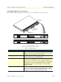
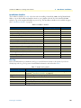
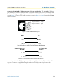
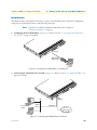
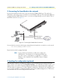
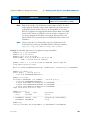
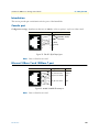
SmartNode 4400 Series rear panels
The SmartNode 4400 rear panel ports are shown in figure 3 and described in table 3 on page 18.
Figure 3. SmartNode 4400 rear panels
Table 3. Port descriptions
Port Description
ETH 0/0 (WAN Ethernet 0/0 port) 10/100Base-Tx full-/half-duplex, RJ-45, auto detection and auto-
MDI-X connects the unit to an Ethernet WAN device (for example,
a cable modem, DSL modem, or fiber modem).
ETH 0/1 (LAN Ethernet 0/1 port) 10/100Base-Tx full-/half-duplex, RJ-45, auto detection and fall-
back, connects the unit to an Ethernet LAN.
Console (RS-232 control port) Used for service and maintenance, the Console port, an RS-232
RJ-45 connector with EIA-561 pinout, connects the router to a
serial terminal such as a PC or ASCII terminal (also called a dumb
terminal). Asynchronous default data rate 9600 bps, hardware
DSR and DTR signals for external modems are wired directly
together internally
FXS Ports (4400/JS models) For connection of up to 32 analog FXS devices (selectable for 12,
16, 24, or 32). Either a 50-pin or 64-pin RJ21X connector that
connects the router to an analog terminal (a telephone, for exam-
ple) FXO port. EuroPOTS support (ETSI EG201 188).
Model SN4432
44xx/JS/UI
10
0
-24
0
V
(5
0
-6
0 H
z
)
1
A
M
P
U
N
I
T
E
Q
U
I
P
P
E
D
W
I
T
H
D
U
A
L
S
U
P
P
L
I
E
S
D
I
S
C
O
N
N
E
C
T
B
O
T
H
S
U
P
P
L
I
E
S
B
E
F
O
R
E
S
E
R
V
I
C
I
N
G
ETH
0/0
C
o
nsole
T
e
lco
Ports
5
0
R
ese
t
E
TH
0/1
44xx/JS/48
Ethernet ports
Console port
Telco ports
36-72V
1.6 AMP
100-240V
(50-60 Hz)
1 AMP
Telco Ports
100-240V
(50-60 Hz)
1 AMP
ConsoleReset ConsoleResetETH 0/0ETH 0/1 ETH 0/0ETH 0/1
Telco PortsConsoleReset ConsoleResetETH 0/0ETH 0/1 ETH 0/0ETH 0/1

SmartNode 4400 Series detailed description 19
SmartNode 4400 Series Getting Started Guide 1 • General information
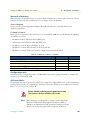
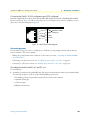
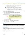
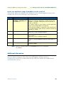
Reset button behavior
For those SmartNode devices that have a Reset button on the rear panel, its behavior is as follows:
• To restart the unit with the current startup configuration—Press for less than 1 second and release the Reset
button. The SmartNode will restart with the current startup configuration.
• To restart the unit with factory default configuration—Press the Reset button for 5 seconds until the Power
LED starts blinking. The unit will restart with factory default configuration.
• To restart the unit in bootloader mode (to be used only by trained SmartNode technicians)—Start with the
unit powered off. Press and hold the Reset button while applying power to the unit. Release the Reset button
when the Power LED starts blinking so the unit will enter bootloader mode.

20
Chapter 2 Applications overview
Chapter contents
Introduction..........................................................................................................................................................21
SmartNode 4400 Series applications......................................................................................................................21
Enterprise FXS concentration and extension over IP and T1/E1 .....................................................................21
Bulk analog line extensions .............................................................................................................................22
Legacy MTU/MDU migration to VoIP based networks .................................................................................22
Page is loading ...
Page is loading ...
Page is loading ...
Page is loading ...
Page is loading ...
Page is loading ...
Page is loading ...
Page is loading ...
Page is loading ...
Page is loading ...
Page is loading ...
Page is loading ...
Page is loading ...
Page is loading ...
Page is loading ...
Page is loading ...
Page is loading ...
Page is loading ...
Page is loading ...
Page is loading ...
Page is loading ...
Page is loading ...
Page is loading ...
Page is loading ...
Page is loading ...
Page is loading ...
Page is loading ...
Page is loading ...
Page is loading ...
Page is loading ...
Page is loading ...
Page is loading ...
Page is loading ...
Page is loading ...
Page is loading ...
Page is loading ...
Page is loading ...
Page is loading ...
Page is loading ...
Page is loading ...
Page is loading ...
Page is loading ...
Page is loading ...
Page is loading ...
Page is loading ...
Page is loading ...
Page is loading ...
Page is loading ...
Page is loading ...
-
 1
1
-
 2
2
-
 3
3
-
 4
4
-
 5
5
-
 6
6
-
 7
7
-
 8
8
-
 9
9
-
 10
10
-
 11
11
-
 12
12
-
 13
13
-
 14
14
-
 15
15
-
 16
16
-
 17
17
-
 18
18
-
 19
19
-
 20
20
-
 21
21
-
 22
22
-
 23
23
-
 24
24
-
 25
25
-
 26
26
-
 27
27
-
 28
28
-
 29
29
-
 30
30
-
 31
31
-
 32
32
-
 33
33
-
 34
34
-
 35
35
-
 36
36
-
 37
37
-
 38
38
-
 39
39
-
 40
40
-
 41
41
-
 42
42
-
 43
43
-
 44
44
-
 45
45
-
 46
46
-
 47
47
-
 48
48
-
 49
49
-
 50
50
-
 51
51
-
 52
52
-
 53
53
-
 54
54
-
 55
55
-
 56
56
-
 57
57
-
 58
58
-
 59
59
-
 60
60
-
 61
61
-
 62
62
-
 63
63
-
 64
64
-
 65
65
-
 66
66
-
 67
67
-
 68
68
-
 69
69


Patton electronic 4400 User manual
- Category
- Gateways/controllers
- Type
- User manual
Ask a question and I''ll find the answer in the document
Finding information in a document is now easier with AI
Related papers
-
Patton electronic 4900 User manual
-
-
-
-
Patton SmartNode 5300 User manual
-
Patton electronics 4940 User manual
-
-
-
-
Other documents
-
Allnet ALL0493 Owner's manual
-
-
-
-
 Commercial Electric B4684CW002 User manual
-
-
-
-
-
Kensington K38074USA User manual
