Page is loading ...

Instruction Manual
(ver. IW)
IW-1
IW-2
IW-3
IW-4
IW-5

2
iPort ver. IW
Instruction Manual
Introduction
The iPort™ In-Wall Docking System allows an Apple iPod
®
to become part of a
whole-home audio system, and/or to be used as a source in a variety of local audio
systems. Before installing and using the iPort please read and follow all of the
instructions in this guide carefully.
iPort System Components and Capabilities
This manual covers five iPort systems (IW-1 – IW-5). Each system has different
capabilities and includes different components.
Note: Except where noted, connections and installation are the same for
all five systems.
IW-1 System (#70001) Capabilities:
• Delivers local-zone unbalanced audio from iPod (up to 20 feet).
• Allows for line-level volume control (requires an optional #70071 or #70072
line-level volume control).
• Charges the iPod while it is docked.
IW-1 System Box Contents:
• (1) iPort In-Wall Docking System
• (1) iPort Unbalanced Audio Wallplate
• (1) 15V DC Regulated Power Supply
IW-2 System (#70002) Capabilities:
• All IW-1 capabilities PLUS:
• Allows line-of-sight IR remote control of iPod functions (requires optional iPort
#70031 or #70032 remote control unit, or a compatible 3rd-party remote).
IW-2 System Box Contents:
• (1) iPort In-Wall Docking System (with IR control capability)
• (1) iPort Unbalanced Audio Wallplate
• (1) 15V DC Regulated Power Supply
IW-3 System (#70003) Capabilities:
• All IW-2 capabilities PLUS:
• Delivers long-distance balanced audio from iPod (up to 500 feet).
• Allows extensive long-distance IR control of iPod functions via Wallplate IR connection (requires compatible 3rd-party controller).
Required Tools
The following tools are required
to install the iPort:
• #2 Phillips screwdriver
• Wire cutters and wire
strippers
• RJ-45 cable crimp tool and
modular connectors
• Sheet rock saw (if retrofitting
in an existing wall)
• Small flat-head screwdriver
(if using an optional line-level
volume control)

3
IW-3 System Box Contents:
• (1) iPort In-Wall Docking System (with IR control and balanced audio capability)
• (1) iPort Balanced Audio Wallplate
• (1) 15V DC Regulated Power Supply
IW-4 System (#70004) Capabilities:
• All IW-3 capabilities PLUS:
• Allows extensive long-distance RS-232 control of iPod functions with 2-way communication (requires compatible
3rd-party controller).
IW-4 System Box Contents:
• (1) iPort In-Wall Docking System (with IR control, balanced audio and RS-232 capability)
• (1) iPort Balanced Audio Wallplate
• (1) RS-232 Cable (RJ-11-to-DB-9 connections)
• (1) 15V DC Regulated Power Supply
IW-5 System (#70005) Capabilities:
• All IW-4 capabilities PLUS:
• Delivers long-distance balanced video from iPod photo players
IW-5 System Box Contents:
• (1) iPort In-Wall Docking System (with IR control, balanced audio, balanced video and RS-232 capability)
• (1) iPort Balanced Video Wallplate
• (1) iPort Balanced Audio Wallplate
• (1) RS-232 Cable (RJ-11-to-DB-9 connections)
• (1) 15V DC Regulated Power Supply
iPod Models Supported
All iPort IW systems can be used with the following iPod models: iPod photo, iPod mini, 4th Generation iPod with Click Wheel,
3rd Generation iPod with touch wheel and buttons. See
Adjusting the iPort for Different iPod Models
, on page 10.
Selecting an Installation Location
The iPort is designed for installation and use in normal interior environments. When selecting an installation location for the
iPort, please consider the following:
• The iPort is not waterproof, nor is it water-resistant. Do not install the iPort outside or in a humid or wet environment.
• The iPort cutout is 4” (102mm) wide x 5
9
/16” (141mm) high. There also must be at least 3½” (89mm) depth within the wall
cavity for the iPort and its connections.
iPort ver. IW
Instruction Manual

4
iPort ver. IW
Instruction Manual
• The iPort has angled screw mounting holes on both sides that allow it to be installed up against a stud. (See
Installing The
iPort In A Wall
, on page 9.)
• Direct sunlight can interfere with IR operation. Avoid installation locations that are in direct sunlight a portion of the day.
iPort Rear-Panel Connections
See
Figure 2
RJ-45 Video Connection: Connects to the iPort Video Wallplate by Cat5 cable. Transmits balanced or
unbalanced NTSC video from iPod photo players to the Video Wallplate.
RJ-45 Audio Connection: Connects to the iPort Audio Wallplate via Cat5 cable. Transmits balanced or
unbalanced audio to the Wallplate; receives IR from and transmits/receives RS-232 control data to and from the Balanced
Audio Wallplate; receives +15V DC power
from the Wallplate.
Volume Control YES/NO switch: In the left
(
NO
) position, audio is routed directly to the
RJ-45 Audio Connection; in the right (
YES
)
position, audio is routed in and out through
the 5-Pin Screw Connector (see below).
5-Pin Screw Connector: Connects to an
optional #70071 or #70072 Line-Level
Volume Control, providing volume control in
local-zone systems (see above).
4-Pin Screw Connector: Connects to the
Aux Power
connector on the Audio
Wallplate. Allows the use of large-gauge
wire to minimize power supply voltage loss
in installations where the Wallplate is locat-
ed more than 250 feet from the iPort.
Note: The 4-Pin connector has two parallel
sets of Supplemental Power connections.
You can use either set.
In addition to the above connections, the
rear panel also has two RotoLock
®
clamps.
When properly tightened, the RotoLock
clamps hold the iPort firmly on the mount-
ing surface. (See
Installing the iPort in a
Wall
, page 9.)
Figure 2:
iPort Utility Box Connections

5
iPort ver. IW
Instruction Manual
iPort System Connections — IW-1 / IW-2
See
Figure 3
IW-1 and IW-2 systems’ unbalanced audio output is designed for use in a local-zone system where the audio equipment is locat-
ed less than 20 feet from the iPort. In IW-1 systems the iPod is controlled only from its front panel; in IW-2 systems the iPod
can be controlled from its front panel or from an optional #70031 or #70032 IR remote control (or compatible 3rd-party remote).
1. Before making connections, run a length of Cat5 cable through the wall from the iPort location to the iPort Wallplate location.
• Find a location for the Wallplate that is near both a source of AC power and the local-zone audio system.
2. Install RJ-45 connectors on both ends of the Cat5 cable as explained in the
Cat5/RJ-45 Cable Wiring
sidebar on page 6.
The unbalanced audio RJ-45 pin assignment is:
Pin 1: R ch from VCLL to iPort
Pin 2: L ch from VCLL to iPort
Pin 3: Ground
Pin 4: R ch from iPort to VCLL
Pin 5: L ch from iPort to VCLL
VOLUME CONTROL
WIRING
Figure 3:
IW-1 & IW-2 Local-Zone
System Connections
Pin 1: Data Receive
Pin 2: Data Transmit
Pin 3: Audio Left
Pin 4: Unused
Pin 5: Audio Right
Pin 6: Unused
Pin 7: Ground
Pin 8: +15V

iPort ver. IW
3a. If the system includes a #70071 or #70072 line-
level volume control, set the iPort’s Volume
Control YES/NO switch to the right (
YES
) position
(volume control in system).
3b. Use 5-conductor twin-shielded wire to connect the
volume control to the iPort 5-pin connector block.
To avoid noise, connect the wires as shown in
Figure 3
.
The volume control connector pin assignments are:
Pin 1: R ch line-level audio from volume control to
iPort
Pin 2: L ch line-level audio from volume control to
iPort
Pin 3: Ground
Pin 4: R ch line-level audio from iPort to volume
control
Pin 5: L ch line-level audio from iPort to volume
control
Note: Do not use Cat5 wire to make these
connections. This wire carries high-imped-
ance unbalanced line-level audio and must
be twin-shielded to avoid noise. Two stan-
dard stereo RCA audio cables with the ends
removed will also work for this application.
4. Plug the RJ-45 connectors into the
Audio
jack on
the iPort and the RJ-45 jack on the Wallplate.
5. Install the Unbalanced Audio Wallplate in an electrical
box in the room where the audio equipment is located.
Important: Do
not
install the iPort Wallplate in
the same electrical box as AC house wiring, a
light switch or any other high-voltage device or
control. The Wallplate can share gang boxes with
other iPort Wallplates or with controls such as
A/B speaker switches, infrared receivers and vol-
ume controls, if these other devices are rated as
Class 2 devices according to the National
Electrical Code.
6. Plug the included 15V DC power supply into the
Power
connector on the iPort Wallplate.
Cat5/RJ-45 Cable Wiring
All RJ-45 cables used in iPort installations must be wired
according to the T568A (“Straight-Through”) Standard, with
cables wired identically at both ends.
To prepare Cat5/RJ-45 cables for iPort installations:
1. Pull the Cat5 wire through the wall between the desired
locations.
2. Use a stripper or knife to strip about 1” of the cable
jacket off each end of the wire.
• Be careful not to nick any of the individual wires.
3. Untwist the wire
pairs and spread
them flat.
Arrange them as
shown in the dia-
gram.
4. Trim the ends of
the individual
wires to ½” in
length, making
sure that they are
even with each
other. Flatten the
wires against each other, leaving no space between them.
5. Hold the RJ-45 connector clip side-down and insert the
Cat5 wire ends firmly into the connector. Make sure that all
the wires are flat all the way to the very front of the con-
nector.
6. Re-confirm that the color orientation matches the diagram
and that cable jacket fits against the connector stop.
7. Firmly crimp the RJ-45 connector with the crimp tool.
Confirm that the connector is crimped firmly and that all
the wires are flat right up against the front of the connec-
tor. If even one of these wires is incorrect, cut the connec-
tor off the cable and repeat steps 2 – 7 with a new RJ-45
connector.
6
Instruction Manual

7
iPort ver. IW
Instruction Manual
7. Use a stereo RCA audio cable to connect the iPort Wallplate to a source input on the local-zone audio system.
8. After installing the iPort in the wall (see
Installing the iPort in a Wall,
page 9), plug the power supply into a wall outlet.
iPort System Connections — IW-3 / IW-4 / IW-5
See
Figure 4
IW-3, IW-4 and IW-5 systems have balanced audio output that is designed for use in audio systems where the audio equipment
is located up to 500 feet from the iPort. In addition to being controlled from its front panel and by an optional #70031 or
#70032 IR remote control, the iPod in IW-3 systems can be controlled by non line-of-sight IR control devices. In IW-4 and IW-5
systems the iPod can also be controlled by RS-232 control devices, with 2-way communication (including iPod metadata).
1. Before making connections, run a length of Cat5 cable through the wall from the iPort location to the iPort Wallplate location.
• Find a location for the Balanced Audio Wallplate that is near both the audio system and a source of AC power.
• For IW-5 systems: Find a location for the Balanced Video Wallplate that is near the video monitor. Run a second Cat5 cable
through the wall from the iPort location to the Balanced Video Wallplate location. Maximum length for the video Cat5
cable is 250 feet.
2. Install RJ-45 connectors on both ends of the Cat5 cables as explained in the
Cat5/RJ-45 Cable Wiring
sidebar on page 6.
The Balanced Audio RJ-45 pin assignment is: The Balanced Video RJ-45 pin assignment is:
Figure 4:
IW-3, IW-4 & IW-5 Long-Distance
Balanced Audio Connections
Pin 1: Data Receive
Pin 2: Data Transmit
Pin 3: Audio Left +
Pin 4: Audio Left –
Pin 5: Audio Right +
Pin 6: Audio Right –
Pin 7: Ground
Pin 8: +15V
Pin 1: B Video +
Pin 2: B Video –
Pin 3: S-Video C +
Pin 4: S-Video C –
Pin 5: S-Video Y +
Pin 6: S-Video Y –
Pin 7: Ground
Pin 8: +15V

8
iPort ver. IW
Instruction Manual
3. Set the iPort’s Volume Control YES/NO switch to the left (NO) position (no volume control in system).
• The iPort’s volume control circuit will affect all zones in a multi-zone system. It is designed for use only in a local-zone system.
4. Plug the audio Cat5 cable’s RJ-45 connectors into the
Audio
jack on the iPort and the RJ-45 connector on the Audio Wallplate.
5. Install the iPort Audio Wallplate in an electrical box in the room where the audio equipment is located.
Important: Do
not
install an iPort Wallplate in the same electrical box as AC house wiring, a light switch or any
other high-voltage device or control. The Wallplates can share gang boxes with each other, or with other controls
such as A/B speaker switches, infrared receivers and volume controls, if these other devices are rated as Class 2
devices according to the National Electrical Code.
6. Plug the included 15V DC power supply into the
Power
connector on the Wallplate.
7. Use a stereo RCA audio cable to connect the Wallplate to a source input on the audio system.
8. If the audio system has a compatible IR control output, use a mono 3.5mm mini cable to connect it to the Wallplate’s
IR
connector.
9. If the audio system has a compatible RS-232 control output, connect it to the Wallplate’s RS-232 connector. The Wallplate
accepts a male RJ-11 connector with the following pin configuration:
* Only one GND pin connection is required.
Note: For complete information about RS-232 connections, programming and operation go to www.iportmusic.com.
10. In installations where the Audio Wallplate is located more than 250 feet from the iPort: Run a length of 16/2 speaker
wire through the wall, from the Wallplate’s
Aux Power
2-pin connector to the iPort’s
Supplemental Power
4-pin connector
as shown below in
Figure 5
. (The connector has two parallel sets of terminals — you can use either set.) This will avoid
performance degradation caused by a loss of DC voltage over wire runs longer than 250 feet.
Figure 5:
IW-3, IW-4 & IW-5
Auxiliary Power
Connection
Pin 1: PC RX
Pin 2: GND*
Pin 3: GND*
Pin 4: PC TX
Pin 5: PC RX
Pin 6: Unused

iPort ver. IW
Instruction Manual
11. For IW-5 Systems:
11a. Plug the video Cat5 cable’s RJ-45 connectors into the
Video
jacks on the iPort and the RJ-45 connector on the Video
Wallplate, as shown above in
Figure 6
.
11b. Install the iPort Video Wallplate in an electrical box in the room where the audio equipment is located.
Important: Do
not
install an iPort Wallplate in the same electrical box as AC house wiring, a light switch or any
other high-voltage device or control. The Wallplates can share gang boxes with each other, or with other controls
such as A/B speaker switches, infrared receivers and volume controls, if these other devices are rated as Class 2
devices according to the National Electrical Code.
11c. Connect the Video Wallplate to the video monitor or video distribution system as shown above in
Figure 6
.
Note: You can use both the S-Video and composite video connections simultaneously, if required.
12. After installing the iPort in the wall (see
Installing the iPort in a Wall,
below), plug the power supply into a wall outlet.
Installing the iPort in a Wall
The iPort features an integral RotoLock
®
mounting system for quick mounting directly into existing walls. Once the hole is cut
and the cables are run, you can install the iPort in the wall in a matter of seconds.
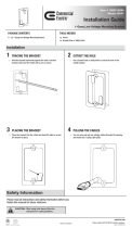
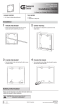
1. Determine the location for the iPort.
2. Perform an obstruction survey to be certain that there are no studs, conduit, pipes, heating ducts or air returns that will
interfere with the iPort.
Note: You can mount the iPort directly next to wall studs on either side (see Step 9, below).
3. The iPort cutout is 4” (102mm) wide x 5
9
/16” (141mm) high. There also must be at least 3½” (89mm) depth within the wall
cavity for the iPort and its connections.
4. Find the cutout template provided in the iPort packaging. Position the template where the iPort is to be located and pencil
an outline on the wall.
Figure 6:
IW-5 Balanced Video
Connections
9

iPort ver. IW
Instruction Manual
• If you are unsure about obstructions, drill a small hole in the center of the outline
and insert a coat hanger wire into the hole to feel-around for possible obstructions.
5. Cut the opening using a drywall saw.
6. Make all cable connections according to
iPort System Connections
, above, bringing
the wires through the wall opening. Double-check that all the connections are correct.
7. Insert the iPort utility box into the opening in the wall.
• First insert the top edge into the opening, then rotate the bottom edge into the
opening.
Note: The RotoLock system can accommodate a maximum wall material
thickness of 1
3
/8”.
8. Hand-tighten the two RotoLock screws on the iPort utility box (see
Figure 7
). The
RotoLock clamps will automatically rotate into position behind the wall and begin
clamping the iPort.
• When you notice resistance on the two screws the iPort has been clamped successfully.
Important: NEVER over-tighten the RotoLock screws.
9. If there are wall studs up against either side of the utility box that prevent the
RotoLock clamps from operating, secure the box by hand-driving a 1½” #6 drywall
screw (not provided) through the angled hole on the side of the chassis and into the
wall stud (see
Figure 7
). Important: Do not over-tighten the drywall screw.
10. Attach the iPort face to the utility box (see
Figure 8
).
• Fit the track on the bottom of the rear chassis into the groove
formed by the two angled capacitors on the underside of the
circuit board at the bottom of the iPod face.
• Slide the face into the chassis until it fits snugly into place.
Adjusting the iPort for Different iPod
Models
The iPort can accommodate the following iPod models: iPod photo,
iPod mini, 4th Generation iPod with Click Wheel, 3rd Generation iPod
with touch wheel and buttons. From the factory it is set-up for any iPod
model with a Dock Connector that is larger than 30GB.
• To adjust the iPort for the iPod mini and other iPods with a Dock
Connector that are 30GB or smaller, extend the iPort’s center disc for-
ward by rotating it counter-clockwise until you feel the first detent
(see
Figure 9,
on page 11). Spring-loaded clamps at the bottom of the
iPod well will hold these smaller models in place.
Figure 8:
Attaching the face
to the utility box
Figure 7:
Attaching the utility box
to a wall
10

11
iPort ver. IW
Instruction Manual
• When switching-back to iPod models with a Dock Connector that are larger than
30GB, retract the iPort’s center disc backwards by rotating it clockwise until you
feel the first detent (see
Figure 9
). When these larger models are placed in the
iPod well the spring-loaded clamps will rotate out of the way.
Controlling the iPod in an iPort System
In IW-1 systems, the iPod is controlled from its own front panel. In IW-2 systems, the
iPod can also be controlled by an optional #70031 or #70032 IR remote. An IR
receiver in the iPort relays commands to the iPod through the dock connector.
In IW-3 systems, IR commands from a compatible control system can be sent to the
iPort from the Balanced Audio Wallplate. In IW-4 and IW-5 systems, compatible
controllers can send IR commands and RS-232 commands to the iPort from the
Balanced Audio Wallplate. These commands are relayed to the iPod through
the dock connector. Two-way communication from the iPod (including iPod
metadata — non-program information such as song titles) is available in IW-4 and
IW-5 systems with RS-232 capability.
IR Control Notes:
• iPort IR codes for universal remotes can be downloaded from
www.iportmusic.com. At press time supported formats are: RTI, Phillips Pronto
style and Universal Electronics (UEI). Check the web site (
www.iportmusic.com
) for the most up-to-date information.
• Third-generation iPod models only respond to the following IR commands:
Play/Pause, Next Song,
and
Previous Song
.
For iPort remote control commands, please see the instruction manual accompanying the remote.
RS-232 Control Notes:
• When the RS-232 control mode is active, the controls on the iPod will not operate (the iPod interface is disabled).
• When the RS-232 control mode is active, the iPod will only respond to the following IR control codes:
Play/Pause, Next
Track, Previous Tracl.
• In IW-5 systems, iPod photo features cannot be controlled in the RS-232 control mode. The iPod must be taken out of the
RS-232 control mode; the photo features can then be controlled from the iPod’s front panel controls. The iPod must be put
back into the RS-232 control mode to control other functions.
• When the RS-232 control mode is active, if the iPod is placed in the dock while in the
Play
mode it will automatically enter
the
Pause
mode. This is due to the iPod protocol. The installer or programmer may wish to set the RS-232 control system
to automatically send a
Play
command to return the iPod to the last playing song when it is inserted in the dock. For RS-
232 commands and programming information, please go to
www.iportmusic.com
.
For RS-232 commands and programming information, please go to
www.iportmusic.com
.
For
iPod mini &
iPods with a
Dock Connector
that are 30GB
or smaller
For
iPods with a
Dock Connector
that are larger
than 30GB
Rotate
Disc
Figure 9:
Adjusting the iPort for
different iPod models

12
iPort ver. IW
Instruction Manual
iPort Status Indication
The logo on the iPort front panel serves as a status indicator (see
Figure
10,
on page 12).
There are 3 illumination levels: BRIGHT, MEDIUM, and DIM. There is also an
OFF setting.
Factory Default Settings:
• When the iPort is first installed, the LED illuminates DIM* for 2 minutes,
then turns OFF.
• When an iPod is inserted in the iPort, the LED illuminates BRIGHT* for
2 minutes, then turns OFF.
• When the iPod is removed from the iPort, the LED illuminates DIM* for
2 minutes, then turns OFF.
* The user can change these settings to any of the 3 illumination
levels via RS-232 or either model iPort remote.
All ON Mode: The installer or user can defeat the 2-minute turn-off function (the LED will operate as above, but will not turn
OFF after 2 minutes) via RS-232 or either model iPort remote.
All OFF Mode: The installer or user can turn the LED OFF in all modes via RS-232 or either model iPort remote.
Note: If power to the iPort is lost or the power supply is disconnected, the iPort will return to the Factory
Default Settings.
Specifications
Frequency Response: 20Hz – 20kHz (±0.25dB) @ 500 ft. Cat5
THD+Noise: < 0.015%, 20Hz – 20kHz @ 500 ft. Cat5
Signal to Noise: > 90dB (A wtd.) @ 500 ft., Cat5
Maximum signal input: 1.5V RMS
Power supply: 15V DC, regulated
Dimensions (W x H x D): 4¾” x 6
5
/16” x 3½” (121mm x 160mm x 89mm)
Cutout Dimensions (W x H): 4” x 5
9
/16” (102mm x 141mm)
Figure 10:
iPort Status
Indicator

13
iPort ver. IW
Instruction Manual
Technical Assistance and Service
If you any have questions about the operation or installation of this product, please call our Technical Assistance
Department at (800) 582-0772 or (949) 492-7777; from 7 a.m. to 5 p.m., Pacific Time, Monday – Friday.
If your iPort should need repair or service, contact your iPort Authorized Dealer for help, or use the following procedure:
1. Prior to calling, note the product’s model number, serial number, purchase date, and the name and address of the dealer
where you purchased the product.
2. Contact our Technical Assistance Department at the above number(s) and describe the problem the unit is experiencing.
If applicable, they will issue a Return Authorization Number.
IMPORTANT: YOU MUST HAVE PRIOR AUTHORIZATION TO RETURN YOUR iPort!
3. If you’re directed to return the unit to iPort for repair, pack the unit in its original shipping carton. If needed, you can obtain
replacement packaging from us for a small charge. Note: it is best if you place the box into an additional outer “overcar-
ton” before shipment to minimize a chance of theft in shipment. Please include a copy of the original bill of sale inside the
package.
4. Contact a package delivery service such as United Parcel Service or Federal Express, to arrange prepaid (not collect) ship-
ping. Do not use the U.S. Postal Service.
IMPORTANT: Freight collect shipments will be refused.
5. Write the Return Authorization Number on the outside of the shipping carton.
6. Ship the packaged unit to:
Quality Assurance Department
iPort
212 Avenida Fabricante
San Clemente, CA 92672-7531

14
iPort ver. IW
Instruction Manual
WARRANTY COVERAGE (U.S. ONLY)
iPort provides the following coverage for units that fail under normal use and according to these instructions due to a defect
in workmanship or materials: For units installed inside a residence, iPort will, at its option and at no charge, repair or replace
the components of such unit that prove to be defective for a period of one year from the date or purchase. For units installed
inside non-residential locations, iPort will, at its option and at no charge, repair or replace the components of such unit that
prove to be defective for a period of six months from the date of purchase.
For this warranty to be effective, the bill of sale must show that the unit was purchased from an "Authorized iPort Dealer"
and must list the price paid. This warranty shall apply exclusively to the original purchaser.
Furthermore, this warranty shall not apply if:
1) Damage to the unit was caused by accident, abuse, or misuse;
2) The unit was opened, modified, or repaired by unauthorized personnel; or
3) The unit was not used as outlined in the operating instructions.
EXCLUSIONS AND LIMITATIONS
The warranty set forth above is in lieu of all other warranties, express or implied, of merchantability, fitness for a particular
purpose, or otherwise. The warranty is limited to iPort products registered herein and specifically excludes any
damage to loudspeakers and other allied or associated equipment which may result for any reason from use with this
product. iPort shall, in no event, be liable for incidental or consequential damages arising from any breach of this
warranty or otherwise. This warranty gives you specific legal rights, and you may have other rights which vary from state to
state.
©2005 Dana Innovations. All rights reserved.
iPort and RotoLock are trademarks of Dana Innovations. Apple and iPod are trademarks of Apple Computer, Inc.

15
iPort ver. IW
Instruction Manual

san clemente ca | 888
.
45
.
iPort | www.iportmusic.com
33-3873 05/06
/