Page is loading ...

READ AND UNDERSTAND THESE INSTRUCTIONS BEFORE INSTALLING FIXTURE
This fixture is intended for installation in accordance with the National Electrical Code and local regulations. To
assure full compliance with local codes and regulations, check with your local electrical inspector before
installation. To prevent electric shock, turn off electricity at fuse box before proceeding.
Retain these instructions for maintenance reference.
INSTALLATION PROCEDURE FOR: 4X9 AND 9X9 MATRIX SERIES RECESSED
COMPACT FLUORESCENT EMERGENCY LIGHTING FRAME-IN KITS
INSTRUCTION SHEET NO.
IS:4X9EM
A0502
Page 1 of 4
A COMPANY
631 Airport Road, Fall River, MA 02720
IMPORTANT SAFEGUARDS
READ AND FOLLOW ALL SAFETY INSTRUCTIONS
WHEN USING ELECTRICAL EQUIPMENT, BASIC SAFETY PRECAUTIONS SHOULD ALWAYS BE FOLLOWED INCLUDING:
1. Turn off AC power before proceeding.
2. Do not use outdoors.
3. Do not mount near gas or electrical heaters.
4. Do not attempt to service the battery. A sealed, rechargeable, no maintenance battery is used. Do not incinerate
or mutilate; may burst or release toxic materials. Do not short circuit; may cause burns. Battery acid can cause
burns to skin and eyes. If acid is spilled on skin or eyes, flush with fresh water and contact a physician
immediately.
5. Equipment should be mounted in locations and at a height where it will not be readily subject to tampering by
unauthorized personnel.
6. The use of accessory equipment is not recommended by the manufacturer and may cause an unsafe condition.
7. Do not use the equipment for other than intended use.
8. This unit has more than one power supply connection point. To reduce the risk of electrical shock, disconnect both
the normal and the emergency power supplies before servicing.
9. Before servicing to prevent electrical shock, disconnect the battery connectors on the emergency pack (location
on the end of the emergency pack). Make certain that the switch (if the fixture is switched) and the unswitched
lines to the emergency pack are turned off at the fuse box. Servicing should be performed by qualified personnel
only.
10. Be sure all electrical connections are complete before battery (inverter) connectors on emergency Pack are
connected.
11. The emergency battery pack must be fed from the same branch circuit as the AC ballast(s).
12. In switched fixtures, emergency pack must be connected ahead of any local switching.
13. Select the appropriate wiring diagrams to connect the emergency pack and the AC ballasts (see page 4).
SAVE THESE INSTRUCTIONS
4X9142HUEM Shown.

READ AND UNDERSTAND THESE INSTRUCTIONS BEFORE INSTALLING FIXTURE
This fixture is intended for installation in accordance with the National Electrical Code and local regulations. To
assure full compliance with local codes and regulations, check with your local electrical inspector before
installation. To prevent electric shock, turn off electricity at fuse box before proceeding.
Retain these instructions for maintenance reference.
INSTRUCTION SHEET NO.
IS:4X9EM
A0502
Page 2 of 4
A COMPANY
631 Airport Road, Fall River, MA 02720
90
°°
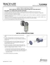
Instructions for replacing BALLAST:
ALL SERVICING MUST BE PERFORMED BY QUALIFIED PERSONNEL ONLY.
1. This unit has more than one power supply connection point. Make certain that the switch (if the fixture is switched) and
the unswitched lines to the EMERGENCY BALLAST (see page 3) are turned off at the fuse box.
2. Disconnect the battery pack INVERTER CONNECTORS (Fig. 1), located inside the SWITCH BOX (see page 3) to
prevent electrical shock from the battery pack.
3. Remove REFLECTOR TRIM & lamp(s) (See IS:4X4, section E.).
4. Undo WINGNUT(s) and remove UPPER REFLECTOR.
5. Remove SCREWS that secure BALLAST PLATE to HOUSING.
6. Partially remove BALLAST PLATE from HOUSING.
7. Disconnect wire leads from BALLAST push-in terminals.
(Insert pin or paper clip in RELEASE SLOT, Fig. 2a)
8. Remove BALLAST from BALLAST PLATE (Fig. 3), and install new BALLAST.
9. Insert wire leads into BALLAST. Follow appropriate wiring diagram on page 4.
10. Reattach BALLAST PLATE, UPPER REFLECTOR, lamp(s), and REFLECTOR TRIM.
FIG. 1
INVERTER
CONNECTORS
UPPER
REFLECTOR
SCREW
HOUSING
WINGNUT
BALLAST
PLATE
FIG. 2a
RELEASE
SLOT
FIG. 2
BALLAST
BALLAST PLATE
FIG. 3
INSTALLATION PROCEDURE FOR: 4X9 AND 9X9 MATRIX SERIES RECESSED
COMPACT FLUORESCENT EMERGENCY LIGHTING FRAME-IN KITS

READ AND UNDERSTAND THESE INSTRUCTIONS BEFORE INSTALLING FIXTURE
This fixture is intended for installation in accordance with the National Electrical Code and local regulations. To
assure full compliance with local codes and regulations, check with your local electrical inspector before
installation. To prevent electric shock, turn off electricity at fuse box before proceeding.
Retain these instructions for maintenance reference.
INSTRUCTION SHEET NO.
IS:4X9EM
A0502
Page 3 of 4
A COMPANY
631 Airport Road, Fall River, MA 02720
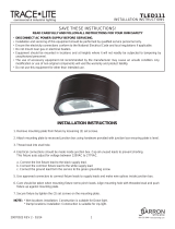
Instructions for replacing EMERGENCY BALLAST:
ALL SERVICING MUST BE PERFORMED BY QUALIFIED PERSONNEL ONLY.
1. This unit has more than one power supply connection point. Make certain that the switch (if the fixture is switched) and
the unswitched lines to the EMERGENCY BALLAST are turned off at the fuse box.
2. To remove SWITCH BOX from ceiling: Disconnect the battery pack inverter connectors (see page 2) located inside the
SWITCH BOX to prevent electrical shock from the battery pack. Disconnect switch and indicator light leads, and
locknut inside SWITCH BOX. Remove SWITCH BOX.
3. Disconnect all EMERGENCY BALLAST connections inside fixture JUNCTION BOX.
4. Disconnect all leads from A/C BALLAST. DO NOT disconnect any wire leads from lamp socket(s). Remove LOCKNUT
from BALLAST PLATE, and remove BALLAST PLATE with A/C BALLAST. See page 2 for detailed instructions on A/C
BALLAST removal and replacement.
5. Loosen RETAINING SCREW on EMERGENCY BALLAST MOUNTING BRACKET, and lift EMERGENCY BALLAST
MOUNTING BRACKET from HOUSING wall.
6. Feed EMERGENCY BALLAST MOUNTING BRACKET and EMERGENCY BALLAST through opening.
7. Remove emergency ballast from MOUNTING BRACKET and replace with new EMERGENCY BALLAST.
8. Re-install all hardware, including fiberglass sleeves over wiring.
9. Re-connect all electrical connections. Follow appropriate wiring diagram on page 4.
SWITCH BOX
JUNCTION BOX
A/C BALLAST
BALLAST PLATE
LOCKNUT
HOUSING
RETAINING SCREW
EMERGENCY BALLAST
MOUNTING BRACKET
VIEW LOOKING INSIDE FIK SIDE VIEW
INSTALLATION PROCEDURE FOR: 4X9 AND 9X9 MATRIX SERIES RECESSED
COMPACT FLUORESCENT EMERGENCY LIGHTING FRAME-IN KITS
EMERGENCY
BALLAST

READ AND UNDERSTAND THESE INSTRUCTIONS BEFORE INSTALLING FIXTURE
This fixture is intended for installation in accordance with the National Electrical Code and local regulations. To
assure full compliance with local codes and regulations, check with your local electrical inspector before
installation. To prevent electric shock, turn off electricity at fuse box before proceeding.
Retain these instructions for maintenance reference.
INSTRUCTION SHEET NO.
IS:4X9EM
A0502
Page 4 of 4
A COMPANY
631 Airport Road, Fall River, MA 02720
TEST
SWITCH
INDICATOR
LIGHT
VIOLET +
WHT -
BLK
BLK
VIOLET
WHT
WHT/BLK
WHT
RED
WHT
2
SWITCH BOX
LAMP 1
WHT
WHT
BLU
BLU/WHT
WHT/BLK
WHT
BLK (120 V)
ORG (277 V)
YEL
YEL
RED
YEL/BLK
YEL
BLU
BLU
YEL
B
B
R
R
Y
Y
W
G
B
GRN
BLK
WHT
BLK (120 V)
ORG (277 V)
COMMON
GROUND
HOT (SWITCHED
OR UNSWITCHED)
EMERGENCY
PACK
A/C
BALLAST
JUNCTION
BOX
LAMP 2
TEST
SWITCH
INDICATOR
LIGHT
VIOLET +
WHT -
BLK
BLK
VIOLET
WHT
WHT/BLK
WHT
RED
WHT
1
SWITCH BOX
LAMP
BLU
BLU/WHT
WHT/BLK
WHT
BLK (120 V)
ORG (277 V)
RED
YEL/BLK
YEL
B
B
R
R
Y
Y
W
G
B
GRN
BLK
WHT
BLK (120 V)
ORG (277 V)
HOT (UN-SWITCHED)
120V (BLK) OR 277V (ORG).
CAP UNUSED LEAD
COMMON
GROUND
HOT (SWITCHED
OR UNSWITCHED)
EMERGENCY
PACK
A/C
BALLAST
JUNCTION
BOX
RED
RED
VIOLET
YEL
WIRING DIAGRAM #1 – 120-277V (26W, 32W, 42W, 4-PIN QT), SINGLE LAMP (4X4 AND 4X9 SERIES)
WIRING DIAGRAM #2 – 120-277V (26W, 32W, 42W, 4-PIN QT), DUAL LAMP (9X9 SERIES)
(LAMP 2 OPERATES IN EMERGENCY MODE)
SELECT PROPER VOLTAGE LEAD.
CAP UNUSED LEAD.
1
2
DO NOT MATE INVERTER CONNECTORS
UNTIL INSTALLATION IS COMPLETE AND
A.C. POWER IS SUPPLIED.
1
HOT (UN-SWITCHED)
120V (BLK) OR 277V (ORG).
CAP UNUSED LEAD
SELECT PROPER VOLTAGE LEAD.
CAP UNUSED LEAD.
1
2
DO NOT MATE INVERTER CONNECTORS
UNTIL INSTALLATION IS COMPLETE AND
A.C. POWER IS SUPPLIED.
REDRED
RED
/