Page is loading ...

Cordex Smart Peripheral
ADIO 4R/8D
4 Output Relays and 8 Digital Inputs
018-591-B2
(
018-590-B2
p
re-RoHS
)

Argus Technologies Ltd. Visit www.argus.ca
Burnaby, British Columbia. Telephone: 604 436 5900 Fax: 604 436 1233
Argus Technologies reserves the right to make changes to the products and information contained in this document without notice.
Copyright 2008 Argus Technologies Ltd. Argus
®
is a registered trademark of Argus Technologies Ltd. All Rights Reserved.
Printed in Canada.
This page intentionally left blank.

Argus Technologies Ltd. 018-591-B2 Rev A WC
Printed in Canada. © 2007 Argus Technologies Ltd. ARGUS and CORDEX are trademarks of Argus Technologies Ltd. All Rights Reserved.
Cordex Smart Peripheral ADIO 4R/8D
4 Output Relays and 8 Digital Inputs
018-591-B2
(018-590-B2 pre-RoHS)
The following documents and drawings are included in this manual to provide the necessary information required for
installation, operation and fault diagnosis of the unit:
• Specifications: 018-591-B1
• Warranty Policy: 048-507-10
• Important Safety Instructions and Installation: 018-591-C0
• Outline Drawing: 018-590-06
• Customer Connections: 018-590-08
• Outline Drawing, Shelf: 030-734-06
• Outline Drawing, Wall Mount: 030-764-06
• Factory Service Information: 048-527-10

MANUAL ADDENDUM
MANUAL ADDENDUM
Unit Description: Cordex Controller Smart Peripherals
Applies to Manuals: 018-568-B2 (Cordex Shunt MUX), 018-569-B2 (2V BCM), 018-571-B2 (12V BCM), and
018-591-B2 (ADIO 4R/8D).
# Date Correction to be implemented
1 08-08-11 For shelf #030-734-20, add List Option 91: (Module) Blank plate, charcoal
2 All drawing references to List 50 should read “List 50 or 56.”
3 All drawing references to List 90 should read “List 90 or 91.”
Authorized by: FORM 954-010-10 018568b2a2_addendum_blnk.doc

SPECIFICATIONS FOR ARGUS’ CORDEX SMART PERIPHERAL 4 O/P RELAYS, 8 DIGITAL I/P
Argus Technologies Ltd. 018-591-B1 Rev A WC
Printed in Canada. © 2007 Argus Technologies Ltd. ARGUS and CORDEX are trademarks of Argus Technologies Ltd. All Rights Reserved. Page 1 of 2
Basic Unit
Input Voltage: ± 9 to 60VDC (supply)
Relay Outputs: 4 Form C per module
Digital Inputs: 8 per module
Software: Cordex Controller Software version 1.9 (minimum requirement)
Communications Bus Length: Maximum 100m (328 ft) from CAN bus controller to the end CAN Termination
[Maximum 16 peripheral modules on CAN bus]
Standards: EN55022 radio interference class B
EN6100-4-3 radiated EMI (susceptibility) level A
Interface
Rear Panel: LEDs for Power ON and Module Acquired
Internal: RJ-12 offset connectors (CAN in and CAN out) to daisy-chain modules for
Cordex Series communications;
Jumper for CAN Termination selection
Mechanical
Mounting: 19”/23” relay rack (flush/offset), wall, stand-alone
Module Size: 40.6mm H x 211.5mm W x 197.3mm D
(1.6” H x 8.33” W x 7.77” D)
Shelf Size: 44mm H x 432mm W x 178mm D
(1.75” H x 17” W x 7” D)
[all dimensions do not include mounting brackets]
Environmental
Temperature: -40 to 75°C operating
(-40 to 167°F)
-40 to 85°C storage
(-40 to 185°F)
Humidity: 0 to 95% non-condensing
Recommended Connection Wire Sizes (as per UL/CSA)
Temperature Range: 0 to 50°C
(32 to 122°F)
Wire Size: 4.0 to 0.34mm
2
(#12 to #22 AWG)

SPECIFICATIONS FOR ARGUS’ CORDEX SMART PERIPHERAL 4 O/P RELAYS, 8 DIGITAL I/P CONTINUED
Argus Technologies Ltd. 018-591-B1 Rev A WC
Printed in Canada. © 2007 Argus Technologies Ltd. ARGUS and CORDEX are trademarks of Argus Technologies Ltd. All Rights Reserved. Page 2 of 2
Part Numbers and List Options
Product is available to order under the following part numbers and list options:
Description Part Number/List Option
Cordex Smart Peripheral 4 O/P Relays, 8 Digital I/P (pre-RoHS 018-590-20)..........................................018-591-20
Basic module, horizontal connectors (see also stand-alone PCB 707-607-20 below)......................................*List 0
Gray finish with blue silkscreen..........................................................................................................................List 50
Charcoal finish with white (contrasting) silkscreen..........................................................................................*List 56
Shelf, Cordex Smart Peripheral (fits 2 modules)........................................................................................030-734-20
Basic shelf..........................................................................................................................................................*List 0
Universal mounting brackets, SEE OUTLINE DRAWING FOR MOUNTING OPTIONS.................................*List 18
Gray finish with blue silkscreen..........................................................................................................................List 50
Charcoal finish with white (contrasting) silkscreen..........................................................................................*List 56
Module blank......................................................................................................................................................List 90
Wall Mount Shelf, Cordex Smart Peripheral (fits 1 module)......................................................................030-764-20
Basic shelf..........................................................................................................................................................*List 0
Gray finish with blue silkscreen..........................................................................................................................List 50
Charcoal finish with white (contrasting) silkscreen..........................................................................................*List 56
Cordex Smart Peripheral 4 O/P Relays, 8 Digital I/P, Stand-alone PCB (pre-RoHS 707-604-20)............707-607-20
Basic module......................................................................................................................................................*List 0
Horizontal Connectors (for chassis mounted model, see 018-591-20 above)...................................................List 80
Vertical Connectors..........................................................................................................................................*List 81
* Default option
The above information is valid at the time of publication. Consult factory for up-to-date ordering information.
Specifications are subject to change without notice.

MANUAL ADDENDUM
MANUAL ADDENDUM
Unit Description: Cordex Controller Smart Peripherals
Applies to Manuals: 018-568-B2 (Cordex Shunt MUX), 018-569-B2 (2V BCM), 018-571-B2 (12V BCM), and
018-591-B2 (ADIO 4R/8D).
# Date Page# Correction to be implemented
1 08-06-04 2 (specs)
of 018-568-B1
of 018-569-B1
of 018-571-B1
of 018-591-B1
Add text:
Description Part Number/List Option
Cable, RJ-12 to RJ-12; sorted by length:
1’ ..................................................................................... 877-176-26
1.5’ .................................................................................. 877-176-21
19” .................................................................................. 877-176-27
2’ ..................................................................................... 877-176-22
6’ ..................................................................................... 877-176-23
12’ ................................................................................... 877-176-24
25’ ................................................................................... 877-176-25
Authorized by: FORM 954-010-10 018591b2a1_addendum_CANcables.doc

Warranty Policy
Argus Technologies Ltd. warrants all equipment manufactured by it to be free from defects in parts
and labor, excluding third party OEM materials (example: air conditioners, batteries), for a period of
two years from the date of shipment from the factory. For third party products the OEM’s warranty
shall apply. The liability of Argus applies solely to repairing, replacing or issuing credit (at Argus’ sole
discretion) for any equipment manufactured by it and returned by the customer during the warranty
period. The terms of the warranty are Ex Works (EXW) from Argus’ factory service location.
Argus reserves the right to void the warranty if:
(1) identification marks or serial numbers are removed or altered in any way,
(2) invoice is unpaid, or
(3) defect is the result of misuse, neglect, improper installation, environmental
conditions, non-authorized repair, alteration or accident.
Argus shall not be liable to the customer or other parties for any loss of profits, loss of use, costs for
removal or installation of defective equipment, damages or consequential damages based upon
equipment failure during or after the warranty period. There shall be no other obligations either
expressed or implied. Argus will not honor warranties for batteries and other third party products
without prior written Argus authorization.
Freight Policy
Customer is responsible for all shipping and handling charges (COD and freight collect will not be
accepted without prior approval from Argus Technologies).
Terms of Payment (North America)
Payment terms are net 30 days subject to prior credit approval. All other orders require payment
before shipping.
Terms of Payment (International)
Payment terms are subject to prior approval and are typically through Tele-Transfer.
Return Material Policy
Our RMA policy is designed to ensure prompt, efficient and high quality factory service. A Return
Material Authorization (RMA) number must be obtained before products can be accepted for
servicing by the Argus factory. For returns to an authorized service center (refer to “Authorized
Service Centers” for locations), please consult the individual service center for specific return policies
and instructions.
To obtain a RMA number for a factory return, customers must call the appropriate location with the
product serial and model number, as well as a brief description of the problem, shipment instructions
and billing details.
The original packing container should be used whenever possible. Both the shipping documents
and the outside of the box must have the RMA # clearly marked and the product shipped prepaid to
the Argus factory service center. Argus will endeavor to repair products within five working days of
receipt. Repairs to the returned product are warranted for a period of six months. A service charge
may be applied if no fault is found in the returned product. Argus will not accept products without an
RMA number.
Business Hours
Argus North American office hours are 7:30 am to 5:00 pm (Pacific Standard Time) Monday to Friday.
WARRANTY AND REPAIR INFORMATION
Canada and USA toll free 24 hour emergency technical support:
+
1 888 GO ARGUS (462 7487) Outside North America: +1 604 436 5547
Factory Service Centers
Canada and International
Argus Technologies Ltd.
ATTN: RMA Returns
7033 Antrim Avenue
Burnaby, BC, V5J 4M5 Canada
Tel: +1 604 436 5900
Fax:
+1 604 436 1233
Email: returns@argusdcpower.com
USA
Argus Technologies Inc.
ATTN: RMA Returns
3116 Mercer Avenue
Bellingham, WA, 98225 USA
Tel: +1-360 756 4904
Fax:
+1-360 647 0498
Email: returns-usa@argusdcpower.com
Asia-Pacific
PCM Electronics (Dong Guan) Co., Ltd.
Hongli Industrial Area, Miaobian, Liaobu Town,
Dongguan City, Guangdong Province,
523400 China
Tel: +86 755 8895 3310
Fax:
+86 755 8895 3307
Authorized Service Center
Argentina
Argus Technologies de Argentina
Belen 315, Capital Federal, Buenos Aires,
1407l Argentina
Tel: +54 (11) 4672 4821
Fax:
+54 (11) 4504 4698
Cell: +54 9 (11) 4993 9996
Email: [email protected]
Asia
Argus Technologies Asia Pte Ltd
Blk 6 Tagore Lane #160
Singapore 787570
Tel: +65 6458 8900
Fax:
+65 6458 2122
Australia
CPS National
8/376 Newbridge Rd
Moorebank, NSW, 2170 Australia
Tel: +61 02 9822 8977
Fax:
+61 02 9822 8077
Australia/New Zealand
Alpha Power Systems Pty Ltd
Unit 3, 30 Heathcote Road
Moorebank, NSW, 2170 Australia
Tel: +61 02 9602 8331
Fax:
+61 02 9602 9180
Century Yuasa
37 - 65 Colbalt Street
Carole Park QLD 4300
Australian Sales & Service
Tel: +61 07 3361 6587
Fax:
+61 07 3361 6705
New Zealand Sales & Service
Tel: +64 9 978 6689
Fax:
+64 9 978 6677
Canada
Compower Systems Inc.
118 Tiffield Road
Toronto, ON, M1V 5N2 Canada
Tel: +1 416 293 3088
Fax:
+1 416 293 0671
Europe
Alpha Technologies Europe Ltd.
Cartel Business Estate
Edinburgh Way
Harlow, Essex, CM20 2DU UK
Tel: +44 1279 422110
Fax:
+44 1279 423355
Mexico & Central America
Technologies Argus First De Mexico SA de CV
Anatole France No. 17
Col. Polanco
Mexico City, 11560 Mexico
Tel: +52 55 5280 6990
Fax:
+52 55 5280 6585
South America
Argus Technologies Argentina
Santo Tome 2573, Capital Federal
Buenos Aires, 1416 Argentina
Tel: +54 11 4504 4698
Cell:
+54 9 11 4993 9996
E-pager: [email protected]
Turkey
IPC Enerji Elk San ve TIC AS
Inonu cad. Kanarya sok. No:20
Yenisahra - Kadikoy
Istanbul, Turkey
Tel: +90 216 317 41 42
Fax:
+90 216 472 90 66
048-507-10-I1 Rev S (09/2007)

IMPORTANT SAFETY INSTRUCTIONS
SAVE THESE INSTRUCTIONS
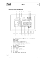
1. Please read this manual prior to use to become familiar with the product’s numerous features and operating
procedures. To obtain a maximum degree of safety, follow the sequences as outlined.
2. This manual provides warnings and special notes for the user:
a. Points that are vital to the proper operation of the product or the safety of the operator are
indicated by the heading: WARNING.
b. A notation that is in Bold Italic typeface covers points that are important to the performance
or ease of use of the product.
3. Before using the product, read all instructions and cautionary markings on the product and any equipment
connected to the product.
4. Do not expose the product to rain or snow; install only in a clean, dry environment.
5. CAUTION – Unless otherwise noted, use of an attachment not recommended or sold by the product
manufacturer may result in a risk of fire, electric shock, or injury to persons.
6. CAUTION – Do not operate the product if it has received a sharp blow, it has been dropped, or otherwise
damaged in any way – return it to a qualified service center for repair.
7. CAUTION – Do not disassemble the product – call our qualified service centers for servicing. Incorrect
reassembling may result in a risk of electrical shock or fire.
i

ii
TABLE OF CONTENTS
1 INTRODUCTION .............................................................................................................................................................1
1.1 Scope of the Manual.....................................................................................................................................1
1.2 Product Overview..........................................................................................................................................1
2 INSPECTION..................................................................................................................................................................2
2.1 Packing Materials..........................................................................................................................................2
2.2 Check for Damage........................................................................................................................................2
3 ASSEMBLY AND INSTALLATION .....................................................................................................................................3
3.1 Module Mounting...........................................................................................................................................3
3.2 Shelf Preparation/Mounting ..........................................................................................................................3
4 WIRING AND CONNECTIONS ..........................................................................................................................................4
4.1 Safety Precautions........................................................................................................................................4
4.2 Tools Required..............................................................................................................................................4
4.3 Connections ..................................................................................................................................................4
5 OPERATION..................................................................................................................................................................5
5.1 Front Panel Display.......................................................................................................................................5
5.2 Front Panel Reset.........................................................................................................................................5
5.3 Can Bus Communications ............................................................................................................................5
5.4 CXC Data Logging........................................................................................................................................5
6 MAINTENANCE .............................................................................................................................................................6
7 ARGUS CONVENTIONS..................................................................................................................................................7
7.1 Numbering System........................................................................................................................................7
7.2 Acronyms and Definitions .............................................................................................................................7

Argus Technologies Ltd. 018-591-C0 Rev A WC
Printed in Canada. © 2007 Argus Technologies Ltd. ARGUS and CORDEX are trademarks of Argus Technologies Ltd. All Rights Reserved. Page 1 of 7
1 Introduction
1.1 Scope of the Manual
This instruction manual explains the installation, interconnection, and operation of Argus Technologies’ Cordex
smart peripheral with four output relays and eight digital inputs (4R/8D).
NOTE: To aid the user with installation, frequent reference is made to drawings located at the rear of the manual.
1.2 Product Overview
The Argus Technologies Cordex Smart Peripherals are designed for remote control and monitoring on
telecommunications power systems that utilize a standard CAN communications bus. The data is gathered by an
advanced system-monitoring unit such as the Argus Cordex Series system controller (CXC); for example, each
channel of the 4R/8D smart peripheral may be stored and viewed on the CXC. The data logging capability of the
CXC (version 1.4 software and greater) may then provide the user with monitoring information in an easy-to-read
table format.
The 4R/8D peripheral module was designed to expand the CXC I/O and has four output relays and eight digital
inputs.
The CXC supports a total of 16 peripheral modules per system; which may include the Shunt MUX or BCM
modules in any combination. The maximum number of relays per system is also 16 including the CXC onboard
relays; however, if you were to configure a system of all 4R/8D modules, the digital inputs would increase to a
maximum of 128 plus the CXC digital inputs.
The CAN communications bus supports a maximum of 125 nodes. Each CXC, or Cordex Smart Peripheral or
Cordex rectifier would count as one node.
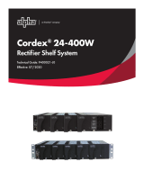
The standard shelf option provides for up to two modules mounted in a standard 1RU, 19” or 23” rack (Figure 1).
A stand-alone PCB and a single module wall mount shelf are also available.
Figure 1–Isometric view of two Smart Peripherals in a common flush mounting shelf

Argus Technologies Ltd. 018-591-C0 Rev A WC
Printed in Canada. © 2007 Argus Technologies Ltd. ARGUS and CORDEX are trademarks of Argus Technologies Ltd. All Rights Reserved. Page 2 of 7
2 Inspection
2.1 Packing Materials
All Argus products are shipped in rugged, double walled boxes and suspended via solid inserts to minimize shock
that may occur during transportation. Packaging assemblies and methods are tested to International Safe Transit
Association standards.
Products are also packaged with Cortex. This plastic wrap contains a corrosive-inhibitor that protects the product
from corrosion for up to two years.
2.1.1 Returns for Service
Save the original shipping container. If the product needs to be returned for service, it should be packaged in its
original shipping container. If the original container is unavailable, make sure the product is packed with at least
three inches of shock-absorbing material to prevent shipping damage.
NOTE: Argus Technologies is not responsible for damage caused by the improper packaging of returned products.
2.2 Check for Damage
Prior to unpacking the product, note any damage to the shipping container. Unpack the product and inspect the
exterior for damage. If any damage is observed contact the carrier immediately.
Continue the inspection for any internal damage. In the unlikely event of internal damage, please inform the
carrier and contact Argus Technologies for advice on the impact of any damage.
Verify that you have all the necessary parts per your order for proper assembly.

Argus Technologies Ltd. 018-591-C0 Rev A WC
Printed in Canada. © 2007 Argus Technologies Ltd. ARGUS and CORDEX are trademarks of Argus Technologies Ltd. All Rights Reserved. Page 3 of 7
3 Assembly and Installation
The following illustration shows the components that make up a typical assembly:
Figure 2–Illustration of typical assembly
The standard shelf consists of a one-piece bottom, sides, and front panel with cutouts. Mounting brackets and a
top cover with screws are also provided. The Cordex Smart Peripheral modules and blanking plates are separate.
NOTE: See drawing 030-764-06 for wall mounting details.
3.1 Module Mounting
The Cordex Smart Peripheral modules (two per shelf maximum) slide from the rear of the shelf. Use the screws
provided with the top cover of the shelf to secure the assembly.
An optional blanking plate (List 90) may be used to cover unused module cutouts (front and rear of shelf); for
example, when only one module is used in a (two-module) shelf.
3.2 Shelf Preparation/Mounting
The standard shelf is supplied with universal-rack mounting brackets and may be mounted in a standard 19” or
23” relay rack. See drawing 030-734-06. Install brackets as required.
NOTE: The shelf shall be mounted in a clean and dry environment.
Secure the shelf to the rack using two #12 – 24 x 1/2” screws in each bracket. Philips-type screws and
screwdriver should be used to eliminate the possibility of slippage and scratching of the unit’s exterior. Washers
(such as internal tooth) or special screws that are designed to cut through the painted surface should be used to
ensure a good chassis ground.

Argus Technologies Ltd. 018-591-C0 Rev A WC
Printed in Canada. © 2007 Argus Technologies Ltd. ARGUS and CORDEX are trademarks of Argus Technologies Ltd. All Rights Reserved. Page 4 of 7
4 Wiring and Connections
NOTE: To aid the user with installation, frequent reference is made to drawings located at the rear of the manual.
4.1 Safety Precautions
WARNING
Hazardous voltages are present at the input of power systems. The DC output from the rectifiers
and battery system, though not dangerous in voltage, has a high short circuit current capacity
that may cause severe burns and electrical arcing.
Before working with any live battery or power system/distribution center, follow these precautions:
• Remove all metallic jewelry; e.g., watches, rings, metal rimmed glasses, necklaces.
• Wear safety glasses with side shields (and prescription lenses if necessary) at all times during installation.
Metallic tools must be insulated.
The installer should follow all applicable local rules and regulations for electrical and battery installations; e.g.,
CSA, UL, CEC, NEC, OSHA, and local fire codes.
4.2 Tools Required
Various tools are essential for product installation. Use this list as a guide:
• Philips head screwdriver, #3 (tip size 1/4”)
• Slot head screwdriver (blade size 1/8”)
• Digital voltmeter equipped with test leads
• Cutters and wire strippers (#12 to #22AWG) (4 to 0.34mm
2
).
4.3 Connections
All wiring connections are accessible at the rear of the module. All cables should be routed together, bundled with
clips (user supplied) and clamped directly into applicable terminal blocks.
NOTE: Unused inputs must be shorted together.
Twist positive and negative wire pairs together to minimize electrical noise pickup.
4.3.1 Grounding
A standoff is provided on the PCB (next to the CAN OUT connector) for earth ground.
4.3.2 Module Input Power
The input power to the module is supplied via the system DC voltage:
• Connect system (+) power bus lead to (+) module supply terminal.
• Connect system (-) power bus lead to (-) module supply terminal.
4.3.3 CAN Serial Ports
Two CAN Serial ports (modular jack with offset latch) for communications with Argus’ Cordex System Controller
and other CAN-enabled equipment (nodes) on the same system, are located at the rear of each module.
Daisy-chain from node to node (CAN OUT of one module to CAN IN of another) as necessary and ensure that
only the last node is terminated as follows:
4.3.3.1 CAN Termination
A jumper allows the CAN bus to be open (to the next module in the system) or terminated. Termination must be
set to “IN” (enabled) only on the final node on the CAN bus; otherwise, set termination to “OUT.”

Argus Technologies Ltd. 018-591-C0 Rev A WC
Printed in Canada. © 2007 Argus Technologies Ltd. ARGUS and CORDEX are trademarks of Argus Technologies Ltd. All Rights Reserved. Page 5 of 7
5 Operation
Cordex Smart Peripheral module operation is controlled via the web browser interface built into the Argus Cordex
Series system controller (CXC). Refer to the CXC Software manual (current version).
5.1 Display
The POWER ON LED will light when valid DC power is connected to the module.
The MODULE ACQUIRED LED will light when the CXC has assumed control of the module. This LED will flash to
signal which module specifically is being monitored/polled; e.g., when a user is querying signals via the CXC. This
allows the user to identify the physical location of the module.
5.2 Reset
To RESET the module, press the respective pushbutton switch. The MODULE ACQUIRED LED will turn off. The
CXC will poll the module after a (brief) preset interval and then attempt to re-acquire the module.
5.3 Can Bus Communications
The CAN bus is used for communication between the Cordex Smart Peripheral module and the CXC; which
consists of commands and data transfer that are used during the operation of the power system to monitor the
status of the module and the equipment connected to the system via the module.
5.4 CXC Data Logging
Data collected from the Cordex Smart Peripherals by the CXC may be exported into a standard spreadsheet
format for analysis. Graphs may then be generated to depict status (e.g. deterioration of a battery) over time.
Records may be taken over a preset interval or when certain conditions are met; such as, charge and discharge
cycles.
NOTE: See CXC Software manual for detailed instruction on programming.

Argus Technologies Ltd. 018-591-C0 Rev A WC
Printed in Canada. © 2007 Argus Technologies Ltd. ARGUS and CORDEX are trademarks of Argus Technologies Ltd. All Rights Reserved. Page 6 of 7
6 Maintenance
Although very little maintenance is required with Argus systems, routine checks and adjustments are
recommended to ensure optimum system performance. Qualified service personnel should do repairs.
The following table lists a few maintenance procedures for this system. These procedures should be performed at
least once a year.
WARNING: HIGH VOLTAGE AND SHOCK HAZARD.
Use extreme care when working inside the shelf while the system is energized.
Do not make contact with live components or parts.
Circuit cards, including RAM chips, can be damaged by static electricity. Always wear a grounded
wrist strap when handling or installing circuit cards.
Procedure Date Completed
Inspect all system connections (re-torque as necessary)
Verify alarm/control settings
Table A–Sample maintenance log
NOTE: There are no field replaceable parts.

Argus Technologies Ltd. 018-591-C0 Rev A WC
Printed in Canada. © 2007 Argus Technologies Ltd. ARGUS and CORDEX are trademarks of Argus Technologies Ltd. All Rights Reserved. Page 7 of 7
7 Argus Conventions
7.1 Numbering System
Argus Technologies uses an eight-digit drawing number system, which is broken into three blocks. The first three
digits describe the category of the product; e.g., rectifier or fuse panel. The next three digits indicate the sequence
in which the product number was allocated in a particular category. The last two digits indicate the type of
drawing, for example:
“-05” Schematic
“-06” Outline Drawing
“-20” Main Assembly
Argus uses an eight-digit part numbering system for all components and sub assemblies. Each part is covered by
its own unique number. Due to the quantity, categories will not be listed within this manual.
7.2 Acronyms and Definitions
AC Alternating current
ANSI American National Standards Institute
AWG American Wire Gauge
CAN Controller area network
CEC Canadian Electrical Code
CSA Canadian Standards Association
CX Cordex series; e.g., CXC for Cordex™ System Controller
DC Direct current
EIA Electronic Industries Alliance
EMI Electromagnetic interference
FCC Federal Communications Commission (for the USA)
IEEE Institute of Electrical and Electronics Engineers
LED Light emitting diode
NEC National Electrical Code (for the USA)
NSTA National Safe Transit Association
OSHA Occupational Safety & Health Administration
RAM Random access memory
UL Underwriters Laboratories

c 2006 ARGUS TECHNOLOGIES
1.60
40.6
8.33
211.5
1.50
38
2006/10
SIZE
DWG NO.
TYPE
B
SHEET
TITLE
ISSUE
DATE
OF
TOLERANCES
SCALE
APPROVED
CHECKED
DRAWN
DESIGN
MATERIAL
FINISH
FOR MANUFACTURING WITHOUT ITS WRITTEN CONSENT.
ARGUS TECHNOLOGIES AND SHALL NOT BE COPIED OR USED
THESE DESIGNS AND SPECIFICATIONS ARE THE PROPERTY OF
REVISIONS
LTR DESCRIPTION
APPDDATE
REV
REDESIGNED - PILOT
4 O/P RELAYS, 8 DIG I/P, ADIO
JLM
JLM
07/01
GS07/01
B
0.01"
0.04"
X.XXX
0.02"
X.X
X.XX
C
0.25mm
DIMENSIONS ADDED
018-590-06
SEE B.O.M.
OUTLINE DWG
Doc. 070-024-83
1 1
RN/WH/RP
JLM
2006/10
2006/10
C
D2
DIMENSIONS ARE IN INCHES WITH METRIC (mm) IN BRACKETS: INCHES [mm]
RN 2006/10
RD
1:2
REV BY
[X] 1mm
[X.X]
0.5mm
[X.XX]
PER P.O. and
GS
FRONT VIEW
(SOME COMPONENETS ARE NOT SHOWN)
(SOME COMPONENTS ARE NOT SHOWN)
TOP VIEW
ISOMETRIC VIEW
SIDE VIEW
17.1
80
3.15
3.33
84.5
199.9
7.87
3.78
95.9
8.18
207.6
47
1.85
0.68
7.78
197.5
7.16
181.9

c 2006 ARGUS TECHNOLOGIES
P10
J2 J1
(SOME COMPONENTS NOT SHOWN)
+ -
REAR VIEW
TOP VIEW
9 - 60VDC
DIGITAL INPUTS
POWER
INPUT
6.
P10
NOT CONNECTED
CAN TERMINATION
5.
JUMPER SETTINGS FOR
PIN OUT (J1)
GND1.
CAN H2.
NOT CONNECTED3.
CAN L4.
6. NOT CONNECTED
CAN OUT RJ12 OFFSET
CAN IN RJ12 OFFSET
PIN OUT (J2)
GND1.
CAN H2.
NOT CONNECTED3.
CAN L4.
NOT CONNECTED5.
NOT CONNECTED
OUTPUT RELAYS
2006/10
SIZE
DWG NO.
TYPE
B
SHEET
TITLE
ISSUE
DATE
OF
TOLERANCES
SCALE
APPROVED
CHECKED
DRAWN
DESIGN
MATERIAL
FINISH
FOR MANUFACTURING WITHOUT ITS WRITTEN CONSENT.
ARGUS TECHNOLOGIES AND SHALL NOT BE COPIED OR USED
THESE DESIGNS AND SPECIFICATIONS ARE THE PROPERTY OF
REVISIONS
LTR DESCRIPTION
APPDDATE
REV
REDESIGNED - PILOT
4 O/P RELAYS, 8 DIG I/P, ADIO
C
JLM
CORRECTED SPELLING
GS07/01
B
0.01"
0.04"
X.XXX
0.02"
X.X
X.XX
JLM
0.25mm
07/01
018-590-08
SEE B.O.M.
CUSTOMER CONNECTION
Doc. 070-024-83
1 1
2006/10
RN/RP/WH
2006/10
JLM
C
D2
DIMENSIONS ARE IN INCHES WITH METRIC (mm) IN BRACKETS: INCHES [mm]
RN 2006/10
RD
NTS
REV BY
[X] 1mm
[X.X]
0.5mm
[X.XX]
PER P.O. and
GS
CAN
IN OUT
OUT
IN
IN
CAN
OUT
17 18 19 20 21 22 23 24 25 26 27 28
NC NC NC NCNO NO NO NOCCC
RELAYS
1234
C
MODULE #1
MODULE
ACQUIRED
POWER ON
DIGITAL INPUTS
1
1234567891
0
11 12 1
3
1
4
1
5
16
2
3
4
56
7
8
3
0
29

22.28 566
18.28 464.4
FRONT VIEW-23" CABINET MOUNT
ISOMETRIC VIEW
SHOWN AS: LIST 0, 18, 50 AND 2 MULTIPLEXERS
SIZE DWG NO.TYPE
B
SHEET
TITLE
ISSUE
DATE
OF
TOLERANCES
SCALE
APPROVED
CHECKED
DRAWN
DESIGN
MATERIAL
FINISH
FOR MANUFACTURING WITHOUT ITS WRITTEN CONSENT.
ARGUS TECHNOLOGIES AND SHALL NOT BE COPIED OR USED
THESE DESIGNS AND SPECIFICATIONS ARE THE PROPERTY OF
REVISIONS
LTR
DESCRIPTION
APPDDATE
REV
X.X
0.04"
X.XX
0.02"
X.XXX
0.01"
[X]
1mm
[X.X]
0.5mm
[X.XX]
0.25mm
030-734-06
OUTLINE, SHELF
CXC PERIPHERALS
PER P.O. and
Doc. 070-024-83
1 2
JU/FL/RD
EOF
2004/08
2004/08
D2
c 2004 ARGUS TECHNOLOGIES
O
B
DIMENSIONS ARE IN INCHES WITH METRIC [mm] IN BRACKETS: INCHES [mm]
RD
2004/08
RD
2004/08
1:2
REV BY
07/08
JLM
NOTE ADDED
B
22.97 583.4
FRONT VIEW-19" CABINET MOUNT
SHOWN AS: LIST 0, 18, 50, 90 AND 1 MULTIPLEXER
LIST 90
BLANK PLATE
ANALOG MULTIPLEXER MODULE
(FLUSH MOUNTING)
16.97 431
18.97 481.8
/