Page is loading ...

Model ProFloSXT Upfl ow
Service Manual
IMPORTANT: Fill in Pertinent Information on Page 3 for Future Reference

Table of Contents
IMPORTANT PLEASE READ:
The information, specifi cations and illustrations in this manual are based on the latest information available at the time of •
printing. The manufacturer reserves the right to make changes at any time without notice.
This manual is intended as a guide for service of the valve only. System installation requires information from a number of •
suppliers not known at the time of manufacture. This product should be installed by a plumbing professional.
This unit is designed to be installed on potable water systems only.•
This product must be installed in compliance with all state and municipal plumbing and electrical codes. Permits may be •
required at the time of installation.
If daytime operating pressure exceeds 80 psi, nighttime pressures may exceed pressure limits. A pressure reducing valve must •
be installed.
Do not install the unit where temperatures may drop below 32°F (0°C) or above 110°F (43°C). •
Do not place the unit in direct sunlight. Black units will absorb radiant heat increasing internal temperatures. •
Do not strike the valve or any of the components.•
Warranty of this product extends to manufacturing defects. Misapplication of this product may result in failure to properly •
condition water, or damage to product.
A prefi lter should be used on installations in which free solids are present. •
In some applications local municipalities treat water with Chloramines. High Chloramine levels may damage valve components.•
Correct and constant voltage must be supplied to the control valve to maintain proper function.•

Job Number: __________________
Model Number: ________________
Water Hardness: ___________________ ppm or gpg
Capacity Per Unit: ______________
Mineral Tank Size: ___________ Diameter: ___________ Height:
Salt Setting per Regeneration: _____________________________________________
1. Type of Timer:
A. 7 Day or 12 Day B. Meter Initiated
2. Downfl ow Upfl ow Upfl ow Variable
3. Meter Size:
A. 3/4” Std Range (125 - 2,100 gallon setting)
B. 3/4” Ext Range (625 - 10,625 gallon setting)
C. 1” Std Range (310 - 5,270 gallon setting)
D. 1” Ext Range (1,150 - 26,350 gallon setting)
E. 1 1/2” Std Range (625 - 10,625 gallon setting)
F. 1 1/2” Ext Range (3,125 - 53,125 gallon setting)
G. 2” Std Range (1,250 - 21,250 gallon setting)
H. 2” Ext Range (6,250 - 106,250 gallon setting)
I. 3” Std Range (3,750 - 63,750 gallon setting)
J. 3” Ext Range (18,750 - 318,750 gallon setting)
K. Electronic __________ Pulse Count __________ Meter Size
4. System Type:
A. System #4: 1 Tank, 1 Meter, Immediate, or Delayed Regeneration
B. System #4: Time Clock
C. System #4: Twin Tank
D. System #5: 2-5 Tanks, 2 Meters, Interlock
E. System #6: 2-5 Tanks, 1 Meter, Series Regeneration
F. System #7: 2-5 Tanks, 1 Meter, Alternating
G. System #9: Electronic Only, 2-4 Tanks, Meter per Valve, Alternating
H. System #14: Electronic Only, 2-4 Tanks, Meter per Valve. Brings units on and offl ine based on fl ow.
5. Timer Program Settings:
A. Backwash: ____________________ Minutes
B. Brine and Slow Rinse: ___________ Minutes
C. Rapid Rinse: __________________ Minutes
D. Brine Tank Refi ll: _______________ Minutes
E. Pause Time: __________________ Minutes
F. Second Backwash: _____________ Minutes
6. Drain Line Flow Control: ____________ gpm
7. Brine Line Flow Controller: __________________ gpm
8. Injector Size#: _____________________
9. Piston Type:
A. Hard Water Bypass
B. No Hard Water Bypass
Job Specifi cation Sheet
Page D

Page 4
Installation Instructions
WATER PRESSURE: A minimum of 20 pounds of water pressure is required for regeneration valve to operate effectively.
ELECTRICAL FACILITIES: An uninterrupted alternating current (A/C) supply is required. Note: Other voltages are available.
Please make sure your voltage supply is compatible with your unit before installation.
EXISTING PLUMBING: Condition of existing plumbing should be free from lime and iron buildup. Piping that is built up heavily
with lime and/or iron should be replaced. If piping is clogged with iron, a separate iron fi lter unit should be installed ahead of
the water softener.
LOCATION OF SOFTENER AND DRAIN: The softener should be located close to a drain to prevent air breaks and back fl ow.
BY-PASS VALVES: Always provide for the installation of a by-pass valve if unit is not equipped with one.
CAUTION: Water pressure is not to exceed 125 psi, water temperature is not to exceed 110°F, and the unit cannot be
subjected to freezing conditions.
Installation Instructions
Place the softener tank where you want to install the unit making sure the unit is level and on a fi rm base.1.
During cold weather, the installer should warm the valve to room temperature before operating.2.
All plumbing should be done in accordance with local plumbing codes. The pipe size for residential drain line should be 3.
a minimum of 1/2”. Backwash fl ow rates in excess of 7 gpm or length in excess of 20’ require 3/4” drain line. Commercial
drain lines should be the same size as the drain line fl ow control.
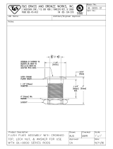
Refer to the dimensional drawing for cutting height of the distributor tube. If there is no dimensional drawing, cut the 4.
distributor tube fl ush with the top of the tank.
Lubricate the distributor o-ring seal and tank “o” ring seal. Place the main control valve on tank. 5.
Note: Only use silicone lubricant.
Solder joints near the drain must be done prior to connecting the Drain Line Flow Control fi tting 6.
(DLFC). Leave at least 6” between the DLFC and solder joints when soldering pipes that are
connected on the DLFC. Failure to do this could cause interior damage to the DLFC.
Tefl on tape is the only sealant to be used on the drain fi tting. The drain from twin tank units may 7.
be run through a common line.
Make sure that the fl oor is clean beneath the salt storage tank and that it is level.8.
Place approximately 1” of water above the grid plate. If a grid is not utilized, fi ll to the top of the 9.
air check in the salt tank. Do not add salt to the brine tank at this time.
On units with a by-pass, place in by-pass position. Turn on the main water supply. Open a cold 10.
soft water tap nearby and let run a few minutes or until the system is free from foreign material
(usually solder) that may have resulted from the installation. Once clean, close the water tap.
Slowly place the by-pass in service position and let water fl ow into the mineral tank. When water 11.
fl ow stops, slowly open a cold water tap nearby and let run until the air is purged from the unit.
Plug unit into an electrical outlet. Note: All electrical connections must be connected according to 12.
local codes. (Be certain the outlet is uninterrupted).
NOTE: Residential
Air Check Valve
Pictured Above

Page 5
Start-Up Instructions
The water softener should be installed with the inlet, outlet, and drain connections made in accordance with the
manufacturer’s recommendations, and to meet applicable plumbing codes.
Turn the manual regeneraton knob slowly in a clockwise direction until the program micro switch lifts on top of 1.
the fi rst set of pins. Allow the drive motor to move the piston to the fi rst regeneration step and stop. Each time
the program switch position changes, the valve will advance to the next regeneration step. Always allow the
motor to stop before moving to the next set of pins or spaces.
NOTE: For electronic valves, please refer to the manual regeneration part of the timer operation
section. If the valve came with a separate electronic timer service manual, refer to the timer operation
section of the electronic timer service manual.
Position the valve to backwash. Ensure the drain line fl ow remains steady for 10 minutes or until the water 2.
runs clear (see above).
Position the valve to the brine / slow rinse position. Ensure the unit is drawing water from the brine tank (this 3.
step may need to be repeated).
Position the valve to the rapid rinse position. Check the drain line fl ow, and run for 5 minutes or until the water 4.
runs clear.
Position the valve to the start of the brine tank fi ll cycle. Ensure water goes into the brine tank at the desired 5.
rate. The brine valve drive cam will hold the valve in this position to fi ll the brine tank for the fi rst regeneration.
Replace control box cover.6.
Put salt in the brine tank.7.
NOTE: Do not use granulated or rock salt.

Page 6
Timer Features
Features of the SXT:
Power backup that continues to keep time and the passage of days for a minimum of 48 hours in the event of •
power failure. During a power outage, the control goes into a power-saving mode. It does not monitor water
usage during a power failure, but it does store the volume remaining at the time of power failure.
Settings for both valve (basic system) and control type (method used to trigger a regeneration).•
Day-of-the-Week controls.•
While in service, the display alternates between time of day, volume remaining or days to regeneration, and •
tank in service (twin tank systems only).
The Flow Indicator fl ashes when outlet fl ow is detected.•
The Service Icon fl ashes if a regeneration cycle has been queued.•
A Regeneration can be triggered immediately by pressing the Extra Cycle button for fi ve seconds.•
The Parameter Display displays the current Cycle Step (BW, BF, RR, etc) during regeneration, and the data •
display counts down the time remaining for that cycle step. While the valve is transferring to a new cycle step,
the display will fl ash. The parameter display will identify the destination cycle step (BW, BF, RR, etc) and the
data display will read “----”. Once the valve reaches the cycle step, the display will stop fl ashing and the data
display will change to the time remaining. During regeneration, the user can force the control to advance to
the next cycle step immediately by pressing the extra cycle button.
Parameter
Display
Data
Display
PM
Indicator
Flow Indicator
x1000 Indicator
Service
Icon
Programming
Icon
Extra Cycle
Button
Up
Button
Down
Button
Error/
Information
Icon

Page 7
Timer Features
Setting the Time of Day
Press and hold either the Up or Down buttons until the programming icon replaces the service icon and the 1.
parameter display reads TD.
Adjust the displayed time with the Up and Down buttons.2.
When the desired time is set, press the Extra Cycle button to resume normal operation. The unit will also 3.
return to normal operation after 5 seconds if no buttons are pressed.
Queueing a Regeneration
Press the Extra Cycle button. The service icon will fl ash to indicate that a regeneration is queued.1.
To cancel a queued regeneration, press the Extra Cycle button.2.
Regenerating Immediately
Press and hold the Extra Cycle button for fi ve seconds.

Page 8
Timer Operation
Meter Immediate Control
A meter immediate control measures water usage and regenerates the system as soon as the calculated system
capacity is depleted. The control calculates the system capacity by dividing the unit capacity (typically expressed
in grains/unit volume) by the feedwater hardness and subtracting the reserve. Meter Immediate systems generally
do not use a reserve volume. However, in twin tank systems with soft-water regeneration, the reserve capacity
should be set to the volume of water used during regeneration to prevent hard water break-through. A Meter
Immediate control will also start a regeneration cycle at the programmed regeneration time if a number of days
equal to the regeneration day override pass before water usage depletes the calculated system capacity.
Meter Delayed Control
A Meter Delayed Control measures water usage and regenerates the system at the programmed regeneration
time after the calculated system capacity is depleted. As with Meter Immediate systems, the control calculates the
system capacity by dividing the unit capacity by the feedwater hardness and subtracting the reserve. The reserve
should be set to insure that the system delivers treated water between the time the system capacity is depleted
and the actual regeneration time. A Meter Delayed control will also start a regeneration cycle at the programmed
regeneration time if a number of days equal to the regeneration day override pass before water usage depletes
the calculated system capacity.
Time Clock Delayed Control
A Time Clock Delayed Control regenerates the system on a timed interval. The control will initiate a regeneration
cycle at the programmed regeneration time when the number of days since the last regeneration equals the
regeneration day override value.
Day of the Week Control
This control regenerates the system on a weekly schedule. The schedule is defi ned in Master Programming by
setting each day to either “off” or “on.” The control will initiates a regeneration cycle on days that have been set to
“on” at the specifi ed regeneration time.
Control Operation During Regeneration
During regeneration, the control displays a special regeneration display. In this display, the control shows the
current regeneration step number the valve is advancing to, or has reached, and the time remaining in that step.
The step number that displays fl ashes until the valve completes driving to this regeneration step position. Once all
regeneration steps are complete the valve returns to service and resumes normal operation.
Pressing the Extra Cycle button during a regeneration cycle immediately advances the valve to the next cycle
step position and resumes normal step timing.
Control Operation During Programming
The control only enters the Program Mode with the valve in service. While in the Program Mode, the control
continues to operate normally monitoring water usage and keeping all displays up to date. Control programming is
stored in memory permanently, eliminating the need for battery backup power.
Manually Initiating a Regeneration
When timer is in service, press the Extra Cycle button for 5 seconds on the main screen.1.
The timer advances to Regeneration Cycle Step #1 (backwash), and begins programmed time count down.2.
Press the Extra Cycle button once to advance valve to Regeneration Cycle Step #2 (brine draw & slow rinse).3.
Press the Extra Cycle button once to advance valve to Regeneration Cycle Step #3 (rapid rinse).4.
Press the Extra Cycle button once to advance valve to Regeneration Cycle Step #4 (brine refi ll).5.
Press the Extra Cycle button once more to advance the valve back to in service.6.
NOTE: If the unit is a fi lter or upfl ow, the cycle step order may change.
NOTE: A queued regeneration can be initiated by pressing the Extra Cycle button. To clear a queued regener-
ation, press the Extra Cycle button again to cancel. If regeneration occurs for any reason prior to the delayed
regeneration time, the manual regeneration request shall be cleared.

Page 9
Control Operation During A Power Failure
The SXT includes integral power backup. In the event of power failure, the control shifts into a power-saving
mode. The control stops monitoring water usage, and the display and motor shut down, but it continues to keep
track of the time and day for a minimum of 48 hours.
The system confi guration settings are stored in a non-volatile memory and are stored indefi nitely with or without
line power. The Time of Day fl ashes when there has been a power failure. Press any button to stop the Time of
Day from fl ashing.
If power fails while the unit is in regeneration, the control will save the current valve position before it shuts down.
When power is restored, the control will resume the regeneration cycle from the point where power failed. Note
that if power fails during a regeneration cycle, the valve will remain in it’s current position until power is restored.
The valve system should include all required safety components to prevent overfl ows resulting from a power
failure during regeneration.
The control will not start a new regeneration cycle without line power. If the valve misses a scheduled
regeneration due to a power failure, it will queue a regeneration. Once power is restored, the control will initiate
a regeneration cycle the next time that the Time of Day equals the programmed regeneration time. Typically,
this means that the valve will regenerate one day after it was originally scheduled. If the treated water output is
important and power interruptions are expected, the system should be setup with a suffi cient reserve capacity to
compensate for regeneration delays.
Timer Operation

Page 10
Master Programming Mode Chart
Master Programming Options
Abbreviation Parameter Option
Abbreviation
Options
DF Display Format
GAL Gallons
Ltr Liters
Cu Cubic Meters
VT Valve Type
St1b Standard Downfl ow/Upfl ow Single Backwash
St2b Standard Downfl ow/Upfl ow Double Backwash
Fltr Filter
UFbF Upfl ow Brine First
Othr Other
CT Control Type
Fd Meter (Flow) Delayed
FI Meter (Flow) Immediate
tc Time Clock
dAY Day of Week
NT Number of Tanks
1 Single Tank System
2 Two Tank System
TS Tank in Service
U1 Tank 1 in Service
U2 Tank 2 in Service
C Unit Capacity Unit Capacity (Grains)
H
Feedwater
Hardness
Hardness of Inlet Water
RS Reserve Selection SF Percentage Safety Factor
rc Fixed Reserve Capacity
SF Safety Factor
Percentage of the system capacity to be used as a
reserve
RC
Fixed Reserve
Capacity
Fixed volume to be used as a reserve
DO Day Override The system’s day override setting
RT Regen Time The time of day the system will regenerate
BW, BD, RR,
BF
Regen Cycle Step
Times
The time duration for each regeneration step. Adjust-
able from OFF and 0-199 minutes.
NOTE: If “Othr” is chosen under “Valve Type”, then
R1, R2, R3, etc, will be displayed instead
D1, D2, D3, D4,
D5, D6, & D7
Day of Week
Settings
Regeneration setting (On or OFF) for each day of the
week on day-of-week systems
CD Current Day The Current day of the week
CAUTION: Before entering Master Programming, please contact your local professional water dealer.

Page 11
Master Programming Mode Chart
Master Programming Options
FM Flow Meter Type
t0.7 3/4” Turbine Meter
P0.7 3/4” Paddle Wheel Meter
t1.0 1” Turbine Meter
P1.0 1” Paddle Wheel Meter
t1.5 1.5” Turbine Meter
P1.5 1.5” Paddle Wheel Meter
Gen Generic or Other Meter
K Meter Pulse Setting Meter pulses per gallon for generic/other fl ow meter
NOTES:
Some items may not be shown depending on timer confi guration.
The timer will discard any changes and exit Master Programming Mode if any button is not pressed for
sixty seconds.
CAUTION: Before entering Master Programming, please contact your local professional water dealer.

Page 12
Master Programming Mode
CAUTION: Before entering Master Programming, please contact your local professional water dealer.
When the Master Programming Mode is entered, all available option setting displays may be viewed and set as
needed. Depending on current option settings, some parameters cannot be viewed or set.
Entering Master Programming Mode
Set the Time Of Day display to 12:01 P.M. Then press and hold the Up and Down buttons together until the
programming icon replaces the service icon and the Display Format screen appears.
Exiting Master Programming Mode
Press the Extra Cycle button to accept the displayed settings and cycle to the next parameter. Press the
Extra Cycle button at the last parameter to save all settings and return to normal operation. The control
will automatically disregard any programming changes and return to normal operation if it is left in Master
Programming mode for 5 minutes without any keypad input.
Resets:
Soft Reset: Press and hold the Extra Cycle and Down buttons for 25 seconds while in normal Service mode.
This resets all parameters to the system default values, except the volume remaining in meter immediate or meter
delayed systems and days since regeneration in the time clock system.
Master Reset: Hold the Extra Cycle button while powering up the unit. This resets all of the parameters in the
unit. Check and verify the choices selected in Master Programming Mode.
1. Display Format (Display Code DF)
This is the fi rst screen that appears when entering Master Programming Mode. The Display Format setting
specifi es the unit of measure that will be used for volume and how the control will display the Time of Day. This
option setting is identifi ed by “DF” in the upper left hand corner of the screen. There are three possible settings:
Display Format Setting Unit of Volume Time Display
GAL U.S. Gallons 12-Hour AM/PM
Ltr Liters 24-Hour
Cu Cubic Meters 24-Hour

Page 13
Master Programming Mode
CAUTION: Before entering Master Programming, please contact your local professional water dealer.
2. Valve Type (Display Code VT)
Press the Extra Cycle button. Use this display to set the Valve Type. The Valve Type setting specifi es the type of
cycle that the valve follows during regeneration. Note that some valve types require that the valve be built with
specifi c subcomponents. Ensure the valve is confi gured properly before changing the Valve Type setting. This
option setting is identifi ed by “VT” in the upper left hand corner of the screen. There are 5 possible settings:
Abbreviation Parameter
St1b Standard Downfl ow/Upfl ow, Single Backwash
St2b Standard Downfl ow/Upfl ow, Double Backwash
Fltr Filter
UFbF Upfl ow Brine First
Othr Other
3. Control Type (Display Code CT)
Press the Extra Cycle button. Use this display to set the Control Type. This specifi es how the control determines
when to trigger a regeneration. For details on how the various options function, refer to the “Timer Operation”
section of this service manual. This option setting is identifi ed by “CT” in the upper left hand corner of the screen.
There are four possible settings:
Meter Delayed: Fd
Meter Immediate: FI
Time Clock: tc
Day of Week: dAY
4. Number of Tanks (Display Code NT)
Press the Extra Cycle button. Use this display to set the Number of Tanks in your system. This option setting is
identifi ed by “NT” in the upper left hand corner of the screen. There are two possible settings:
Single Tank System: 1
Two-Tank System: 2

Page 14
Master Programming Mode
CAUTION: Before entering Master Programming, please contact your local professional water dealer.
5. Tank in Service (Display Code TS)
Press the Extra Cycle button. Use this display to set whether tank one or tank two is in service. This option setting
is identifi ed by “TS” in the upper left hand corner of the screen. This parameter is only available if the number of
tanks has been set to 2. There are two possible settings:
Tank One in Service: U1
Tank Two in Service: U2
6. Unit Capacity (Display Code C)
Press the Extra Cycle button. Use this display to set the Unit Capacity. This setting specifi es the treatment
capacity of the system media. Enter the capacity of the media bed in grains of hardness when confi guring a
softener system, and in the desired volume capacity when confi guring a fi lter system. This option setting is
identifi ed by “C” in the upper left hand corner of the screen. The Unit Capacity parameter is only available if the
control type has been set to one of the metered options. Use the Up and Down buttons to adjust the value as
needed.
7. Feedwater Hardness (Display Code H)
Press the Extra Cycle button. Use this display to set the Feedwater Hardness. Enter the feedwater hardness in
grains per unit volume for softener systems, or 1 for fi lter systems. This option setting is identifi ed by “H” in the
upper left hand corner of the screen. The feedwater hardness parameter is only available if the control type has
been set to one of the metered options. Use the Up and Down buttons to adjust the value as needed.
Range: 1-999,9900 grain capacity
Range: 4-199 hardness

Page 15
Master Programming Mode
CAUTION: Before entering Master Programming, please contact your local professional water dealer.
8. Reserve Selection (Display Code RS)
Press the Extra Cycle button. Use this display to set the Safety Factor. Use this display to select the type of
reserve to be used in your system. This setting is identifi ed by “RS” in the upper left-hand corner of the screen.
The reserve selection parameter is only available if the control type has been set to one of the metered options.
There are two possible settings.
FS Safety Fector
rc Fixed Reserve Capacity
9. Safety Factor (Display Code SF)
Press the Extra Cycle button. Use this display to set the Safety Factor. This setting specifi es what percentage of
the system capacity will be held as a reserve. Since this value is expressed as a percentage, any change to the
unit capacity or feedwater hardness that changes the calculated system capacity will result in a corresponding
change to the reserve volume.This option setting is identifi ed by “SF” in the upper left hand corner of the screen.
Use the Up and Down buttons to adjust the value from 0 to 50% as needed.
10. Fixed Reserve Capacity (Display Code RC)
Press the Extra Cycle button. Use this display to set the Reserve Capacity. This setting specifi es a fi xed
volume that will be held as a reserve. The reserve capacity cannot be set to a value greater than one-half of the
calculated system capacity. The reserve capacity is a fi xed volume and does not change if the unit capacity or
feedwater hardness are changed. This option setting is identifi ed by “RC” in the upper left-hand corner of the
screen. Use the Up and Down buttons to adjust the value as needed.
Range: 0-50%
Range: 0-half the calculated capacity

Page 16
11. Day Override (Display Code DO)
Press the Extra Cycle button. Use this display to set the Day Override. This setting specifi es the maximum
number of days between regeneration cycles. If the system is set to a timer-type control, the day override setting
determines how often the system will regenerate. A metered system will regenerate regardless of usage if the
days since last regeneration cycle equal the day override setting. Setting the day override value to “OFF” disables
this function. This option setting is identifi ed by “DO” in the upper left hand corner of the screen. Use the Up and
Down buttons to adjust the value as needed.
12. Regeneration Time
Press the Extra Cycle button. Use this display to set the Regeneration Time. This setting specifi es the time of day
the control will initiate a delayed, manually queued, or day override triggered regeneration. This option setting is
identifi ed by “RT” in the upper left hand corner of the screen. Use the Up and Down buttons to adjust the value as
needed.
13. Regeneration Cycle Step Times
Press the Extra Cycle button. Use this display to set the Regeneration Cycle Step Times. The different
regeneration cycles are listed in sequence based on the valve type selected for the system, and are identifi ed
by an abbreviation in the upper left-hand corner of the screen. The abbreviations used are listed below. If the
system has been confi gured with the “OTHER” valve type, the regeneration cycles will be identifi ed as R1, R2,
R3, R4, R5, and R6. Each cycle step time can be set from 0 to 199 minutes, or “OFF.” Setting a cycle step to
“OFF” will disable all of the following steps. Setting a cycle step time to 0 will cause the control to skip that step
during regeneration, but keeps the following steps available. Use the Up and Down buttons to adjust the value as
needed. Press the Extra Cycle button to accept the current setting and move to the next parameter.
Cycle Step Abbreviation
BD Brine Draw
BF Brine Fill
BW Backwash
RR Rapid Rinse
SV Service
Master Programming Mode
CAUTION: Before entering Master Programming, please contact your local professional water dealer.
Range: Off-99 days
Range: 0-199 minutes

Page 17
Master Programming Mode
CAUTION: Before entering Master Programming, please contact your local professional water dealer.
14. Day of Week Settings
Press the Extra Cycle button. Use this display to set the regeneration schedule for a system confi gured as a Day
of Week control. The different days of the week are identifi ed as D1, D2, D3, D4, D5, D6, and D7 in the upper
left-hand corner of the display. Set the value to “ON” to schedule a regeneration or “OFF” to skip regeneration for
each day. Use the Up and Down buttons to adjust the setting as needed. Press the Extra Cycle button to accept
the setting and move to the next day. Note that the control requires at least one day to be set to “ON.” If all 7 days
are set to “OFF”, the unit will return to Day One until one or more days are set to “ON.”
15. Current Day (Display Code CD)
Press the Extra Cycle button. Use this display to set the current day on systems that have been confi gured as
Day of Week controls. This setting is identifi ed by “CD” in the upper left-hand corner of the screen. Use the Up
and Down buttons to select from Day 1 through Day 7.
16. Flow Meter Type (Display Code FM)
Press the Extra Cycle button. Use this display to set the type of fl ow meter connected to the control. This option
setting is identifi ed by “FM” in the upper left-hand corner of the screen. Use the Up and Down buttons to select
one of the 7 available settings.
t0.7 Fleck 3/4” Turbine Meter
P0.7 Fleck 3/4” Paddle Wheel Meter
t1.0 Fleck 1” Turbine Meter
P1.0 Fleck 1” Paddle Wheel Meter
t1.5 Fleck 1 1/2” Turbine Meter
P1.5 Fleck 1 1/2” Paddle Wheel Meter
GEn Generic/Other Meter

Page 18
Master Programming Mode
17. Meter Pulse Setting (Display Code K)
Press the Extra Cycle button. Use this display to specify the meter pulse setting for a non-standard fl ow meter.
This option setting is identifi ed by “K” in the upper left-hand corner of the screen. Use the Up and Down buttons to
enter the meter constant in pulses per unit volume.
18. Press the Extra Cycle button to save all settings and exit Master Programming Mode.

Page 19
User Programming Mode
User Programming Mode Options
Abbreviation Parameter Description
DO Day Override The timer’s day override setting
RT Regeneration Time The time of day that the system
will regenerate (meter delayed,
timeclock, and day-of-week
systems)
H Feed Water Hardness The hardness of the inlet water
- used to calculate system capacity
for metered systems
RC Reserve Capacity The fi xed reserve capacity
CD Current Day The current day of week
NOTES:
Some items may not be shown depending on timer confi guration.
The timer will discard any changes and exit User Mode if any button is not pressed for sixty seconds.
User Programming Mode Steps
Press the Up and Down buttons for fi ve seconds while in service, and the time of day is NOT set to 12:01 PM.1.
Use this display to adjust the Day Override. This option setting is identifi ed by “DO” in the upper left hand 2.
corner of the screen.
Press the Extra Cycle button. Use this display to adjust the Regeneration Time. This option setting is identifi ed 3.
by “RT” in the upper left hand corner of the screen.
Press the Extra Cycle button. Use this display to adjust the Feed Water Hardness. This option setting is 4.
identifi ed by “FH” in the upper left hand corner of the screen.
Range: 4-199 hardness

Page 20
Press the Extra Cycle button. Use this display to adjust the Fixed Reserve Capacity. This option setting is 1.
identifi ed by “RC” in the upper left-hand corner of the screen.
Press the Extra Cycle button. Use this display to set the Current Day of the Week. This option setting is 2.
identifi ed by “CD” in the upper left hand corner of the screen.
Press the Extra Cycle button to end User Programming Mode.3.
User Programming Mode
/