18 DPD00962E
FLANGE MOUNT KIT FOR FRAME MR6
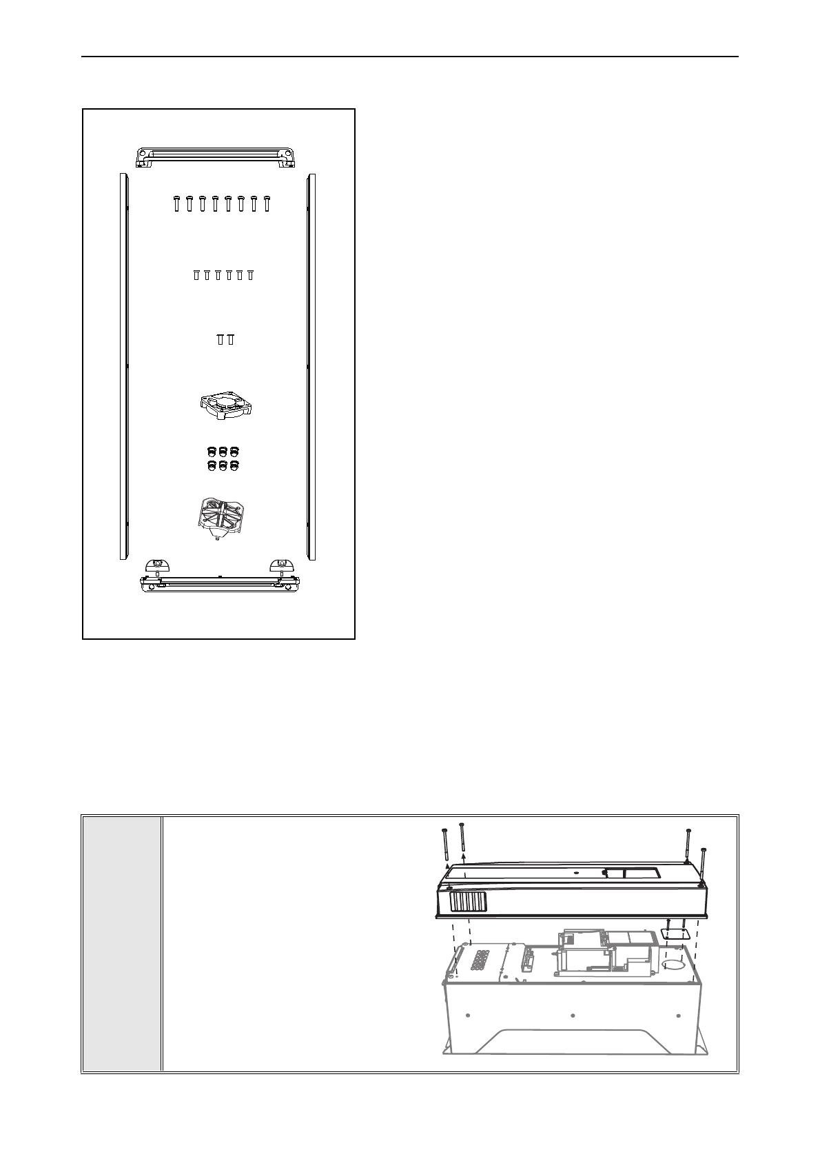
The parts needed in the installation:
1 = Top collar (70CMR00174)
2 = Bottom collar (70CMR00173)
3 = Side collars, 2 pcs (70CMR00145)
4 = Internal fan (70CPE00056)
5 = Sealing plugs, 6 pcs (70CMR00324)
6 = Fan grille 50 mm (70CTC1102509)
7 = Additional fasteners, 2 pcs (70CTC1103801)
Additionally:
8 pcs screws, size 4x16 (for the top and bottom collar
mounting)
6 pcs screws, size 4x12 (for the side collar mounting)
2 pcs screws, size 3.5x10 (for the bottom collar
mounting)
MR6 FLANGE MOUNTING
If your drive is IP21/Type1-protected and there is the risk that dust or other impurities in the cooling
air might end up inside the control unit, start the mounting with actions described in steps 1 to 5.
If this is not needed, install the flange mounting kit proceeding directly to step 6. Note, in this case
the rear will not be according to IP54/Type12.
Please read step 8 first in order to find out if the additional fasteners are needed.
1
Remove the cover of the AC drive.
Also remove the fan block plate.
M4x16
M4x12
1
2
3
3
7
7
M3.5x10
4
5
9271_00
6
9296_00


