Page is loading ...

Dell EMC Networking C9010
Installation Guide
Regulatory Model: C9010

Notes, Cautions, and Warnings
NOTE: A NOTE indicates important information that helps you make better use of your computer.
CAUTION: A CAUTION indicates either potential damage to hardware or loss of data and tells you how to avoid the problem.
WARNING: A WARNING indicates a potential for property damage, personal injury, or death.
Copyright © 2017 Dell Inc. or its subsidiaries. All rights reserved. Dell, EMC, and other trademarks are trademarks of Dell Inc. or its subsidiaries. Other
trademarks may be trademarks of their respective owners.
2017 - 12
Rev. A02

About This Guide
This document provides information about how to install a C9010 switch with the base conguration in a rack. For complete information
about C9010 installation and conguration, refer to these documents:
Table 1. C9010 Documentation
Information Documentation
Hardware installation, power-up, and initial software conguration
instructions
Dell Networking C9010 Getting Started Guide
Software conguration Dell Networking Conguration Guide for the C9000 Series
Command-line interface Dell Networking Command-Line Reference Guide for the C9000
Series
Latest updates Dell Networking C9010 and C1048P Release Notes
1
About This Guide 3

C9010 Hardware Description
The C9010 switch is part of Dell Networking's next-generation LAN solution, providing a scalable switch that oers a path to higher density
10GbE and 40GbE capability. You can deploy the C9010 switch as an access or aggregation/core switch for installations in which a modular
switch is preferred. For larger port requirements, you can also connect C1048P port extenders (PEs) as access devices.
The C9010 switch supports up to two hundred and forty-eight 1GbE, two hundred and forty-eight 10GbE, or sixty 40GbE ports with a
combination of port speeds and media types, such as copper, ber, and direct attach copper (DAC). It is an 8U chassis (18”/45.72 cm
depth) that ts into a standard 19”/48.26 cm rack or cabinet. The C9010 chassis supports the following components:
• Two full-width route processor modules (RPMs) with four 1/10GbE SFP+ uplinks per module
• Ten half-width Ethernet line cards of the following types:
• 6-Port 40 Gigabit Ethernet QSFP+
• 24-Port 1/10 Gigabit Ethernet SFP+
• 24-Port 1/10 Gigabit Ethernet Base-T RJ-45
• Three hot-swappable fan modules with side-to-side airow (draws air through ventilation holes on the right side of the chassis and
expels air through ventilation holes on the left side)
• Four 1450/2900 watt AC power supply units (PSUs)
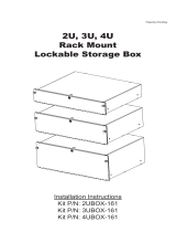
The slot numbers of all installed components are shown in the following gure.
Figure 1. C9010 Chassis — Installed Components with Slot Numbers
Topics:
2
4 C9010 Hardware Description

• Unpacking the Switch
• Before You Start: Site Preparation
Unpacking the Switch
The switch and its accessories ship in a single container. Before unpacking the switch, inspect the container and immediately report any
evidence of damage. Verify that you have received your ordered items. If any item is missing or damaged, contact your Dell Networking
representative or reseller for assistance.
CAUTION: Always wear an electrostatic discharge (ESD)-preventive wrist or heel ground strap when handling the switch and its
components. Ground yourself by using an antistatic wrist strap or other device and connect it to the ESD grounding jack on the
chassis. As with all electrical devices of this type, take all necessary safety precautions to prevent injury when installing this
system.
CAUTION: Use an equipment lift or pallet jack to lift the shipping container with the chassis. Lifting the system by its shelves
causes damage to the chassis.
Unpack the C9010 by carefully removing the device from the container and place it on a secure and clean surface.
C9010 Hardware Description 5

The base C9010 conguration package consists of:
• One C9010 chassis
• One full-width C9000 Series RPM
• C9000-RPM-2.56T displays in SW output.
•
07KPC3 or 0N90RW is on the HW label.
• Three C9000 Series fan modules
• C9000-FAN displays in SW output.
• 0C94MF is on the HW label.
• One AC PSU (110-230V switching)
• C9000-PWR-AC displays in SW output.
• D3000E-S0 is on the HW label.
• AC power cord (IEC 60320 C19 cable)
• One DB-9 to RJ-45 serial console cable
• One rack bar with four screws and washers
• Eight cage nuts (four for the rack bar; four for the chassis thumb screws)
• Blank panels: one RPM, three PSU, and nine half-width line card blanks
• Two cable management brackets
• C9010 Getting Started Guide
• Safety and Regulatory Information
• Warranty and Support Information
• Software License Agreement
In addition, you can order the following items:
• Up to three additional PSUs for redundancy or additional power
• Half-width line cards:
• 6-Port 40 Gigabit Ethernet QSFP+ (C9000LC0640 displays in SW output.)
• 24-Port 1/10 Gigabit Ethernet SFP+ (C9000LC2410G displays in SW output.)
• 24-Port 1/10 Gigabit Ethernet Base-T RJ-45 (C9000LC2410T displays in SW output.)
• SFP+ optics
• QSFP+ optics
• SFP+ direct attach copper (DAC) cables
• QSFP+ DAC cables
• DB-9 adapter
• Dell ReadyRails™ kit (#1 and #2 Phillips and at-tipped screwdrivers required) with four cage nuts
• Rack mount tray
• C1048P port extenders for use with the C9010
Before You Start: Site Preparation
Before installing the C9010 switch, make sure that your installation site meets these requirements:
• Clearance: Ensure there is adequate space in front of the switch so you can read the light-emitting diodes (LEDs) and adequate space
around and behind the chassis for cabling, power connections, airow, and ventilation. Make sure that the AC power cord can reach the
power connector on the front panel of a power supply unit from the power outlet.
• Airow: On the C9010, airow is from the right to the left side as you face the switch. Hot air is expelled from the left side. Ensure that
airow around the switch and through the side vents is unobstructed and that hot exhaust is not used as air intake on the right side.
• Temperature: The ambient temperature around the operating switch should not exceed 113°F (45°C). If the switch is in a closed or
multi-rack assembly, the temperature might be higher than normal room temperature.
6
C9010 Hardware Description

• Cabling: Route the cabling to avoid sources of electrical noise, such as radio transmitters, broadcast ampliers, power lines, and
uorescent lighting xtures. Make sure that the cabling is safely away from other devices that might damage the cables. If needed,
allow 1 RU between devices to provide room for cabling.
• Altitude: Altitude at the installation site is below 10,000 feet (3048 m).
• Humidity: The relative humidity around the operating switch is between 5% and 95% (non-condensing) with 91°F (33°C) maximum
dew point.
• Dust: Install the switch in an environment as free as possible from dust and foreign conductive material (such as metal akes from
construction activities). Cooling mechanisms, such as fans in the switch, can draw dust and other particles inside the chassis, which
can result in system malfunction.
C9010 Hardware Description 7

Installing the Hardware
To install the C9010 chassis and power up the switch:
1 Install the C9010 chassis in a 2- or 4-post rack using the rack bar and mounting brackets shipped with the chassis, or use an optional
rack mount tray or Dell ReadyRails kit.
2 Secure the chassis ground.
3 Install the fan modules.
4 Install RPMs and line cards.
5 Install the power supplies and power cables.
6 Install the cable management system.
7 Install the QSFP+ and SFP+ optics.
8 Connect the power and power up the system.
WARNING: Due to the weight of a fully populated C9010 chassis, remove each component before you install or remove the
chassis.
After you install the switch in a rack and power it up, perform the initial software conguration and connect the switch to a network as
described in the Dell Networking C9010 Getting Started Guide.
Topics:
• Installing the Chassis in a Two-Post Threaded-Hole Rack
• Installing the Chassis in a Four-Post Rack
• Using Dell ReadyRails (Optional)
• Using a Rack Mount Tray (Optional)
• Attaching the Chassis Ground
• Installing a Fan Module
• Installing RPMs and Line Cards
• Installing a Power Supply
• Installing the Cable Management System
• Installing QSFP+ and SFP+ Transceivers
• Powering Up the System
• Checking LED Status
Installing the Chassis in a Two-Post Threaded-Hole
Rack
You can install the chassis in a 2-post threaded-hole rack by following the tooled procedure in this section. A at-head and a Philips
screwdriver are necessary.
WARNING
: Use two people, an equipment lift, or pallet jack when lifting or moving the chassis. Install the chassis into the rack
before inserting the chassis components. Lift the C9010 chassis only from the bottom. Lifting by the chassis shelves or power
supply openings might damage the chassis.
3
8 Installing the Hardware

WARNING: To prevent bodily injury when mounting or servicing this unit in a rack, take special precautions to ensure that the
system remains stable. The following guidelines are provided to ensure your safety:
• If your chassis is the only unit in the rack, mount it at the bottom of the rack.
• When mounting this unit in a partially lled rack, load the rack from the bottom to the top with the heaviest component at the
bottom of the rack.
• If the rack is provided with stabilizing devices, install the stabilizers before mounting or servicing the unit in the rack.
• If the chassis is shipped with blanks, remove the blanks from each RPM, line card, fan module and PSU slot before lifting the
chassis.
1 (Optional) The C9010 chassis is designed to t into a rack enclosure with the front door closed. If you plan to use cable management
brackets (see Installing the Cable Management System ) and close the front door, re-position and fasten the front rack posts 6.5
inches (165 mm) back towards the rear of the rack to leave space for the brackets.
2 Determine the height at which you want to mount the chassis in the equipment rack.
3 Install the rack bar on the front posts just below the desired height of the bottom of the chassis. The rack bar requires 1 RU below the
chassis.
Use the rack bar as a guide to mount the chassis. It is not required to support the weight of the chassis; you can remove it when the
chassis is securely mounted in the rack.
Hold the rack bar (item 1 in Figure 2) so that the smooth side faces outward and the arrows point upward. Attach the bar to the front-
rack posts using the mounting screws and washers provided with the rack bar (items 2 and 3 in Figure 2).
NOTE: The installation procedure in this section describes how to install the C9010 in a 2-post rack using the rack bar
provided in the base conguration package. For information about how to use Dell ReadyRails or a rack mount tray to
install the C9010, follow the instructions in Installing Dell ReadyRails or Installing a Rack Mount Tray. Then continue
with Step 4.
Figure 2. Installing a Rack Bar in a 2-Post Rack
Installing the Hardware
9

4 Using a at-head screwdriver, remove the bracket screws (item 1 in Figure 3) and unscrew the thumb screws to remove the bracket
(item 2 in Figure 3) attached to each chassis ange.
Figure 3. Removing Brackets from the Chassis
10
Installing the Hardware

5 Use an equipment lift or two people to lift the empty chassis without blanks (item 1 in Figure 4) and align the rack-mount screw holes
on each ange of the chassis with the holes in the equipment rack. Rest the chassis on top of the rack bar (or rack tray, if installed).
Slide the chassis so that the holes in the side anges align with the holes in the rack posts. Tighten four rack screws (item 2 in Figure
4) on each chassis ange to attach the chassis to the rack posts. Tighten each group of rack screws by starting with the bottom
screw and working up.
Figure 4. Mounting the Chassis into a 2-Post Rack
Installing the Hardware
11

6 Verify that the chassis is securely installed in the two rack posts and does not sag. To prevent sagging, support the back of the chassis
by using a rack mount shelf or Dell ReadyRails as described in Step 3.
Figure 5. Chassis Installed in a 2-Post Rack
NOTE
: To allow for increased airow, you can remove the rack bar from the front
posts.
Installing the Chassis in a Four-Post Rack
You can install the C9010 chassis in a 4-post round- or square-hole rack by following the tool-less procedure in this section or in a 4-post
threaded-hole rack by following a tooled procedure. The illustrations in this section show how to install the chassis in a 4-post square-hole
rack using a tool-less procedure.
WARNING
: Use two people, an equipment lift, or pallet jack when lifting or moving the chassis. Install the chassis into the rack
before inserting the chassis components. Lift the C9010 chassis only from the bottom. Lifting by the chassis shelves or power
supply openings might damage the chassis.
12 Installing the Hardware

WARNING: To prevent bodily injury when mounting or servicing this unit in a rack, take special precautions to ensure that the
system remains stable. The following guidelines are provided to ensure your safety:
• If your chassis is the only unit in the rack, mount it at the bottom of the rack.
• When mounting this unit in a partially lled rack, load the rack from the bottom to the top with the heaviest component at the
bottom of the rack.
• If the rack is provided with stabilizing devices, install the stabilizers before mounting or servicing the unit in the rack.
• If the chassis is shipped with blanks, remove the blanks from each RPM, line card, fan module and PSU slot before lifting the
chassis.
1 (Optional) The C9010 chassis ts into a rack enclosure with the front door closed. If you plan to use cable management brackets
(Installing the Cable Management System ) and close the front door, re-position and fasten the front rack posts 6.5 inches (165 mm)
back towards the rear of the rack to leave space for the brackets.
2 Determine the height at which you want to mount the chassis in the rack.
Installing the Hardware 13

3 Install the rack bar on the front posts just below the desired height of the bottom of the chassis. The rack bar requires 1 RU below the
chassis.
Use the rack bar as a guide to mount the chassis. It is not required to support the weight of the chassis; you can remove it when the
chassis is securely mounted in the rack. To install the rack bar, rst insert two cage nuts (item 2 in Figure 6) into each post at the
desired height.
Hold the rack bar (item 1 in Figure 6) so that the smooth side faces outward and the arrows point upward. Align the holes in the rack
bar with the cage nuts in the posts. Attach the bar to the front-rack posts using the mounting screws and washers shipped with the
rack bar (items 3 and 4 in Figure 6). Tighten each screw to secure the rack bar to the posts.
NOTE: The installation procedure in this section describes how to install the C9010 in a 4-post rack using the rack bar
provided in the base conguration package. For information about how to use Dell ReadyRails or a rack mount tray to
install the C9010, follow the instructions in Installing Dell ReadyRails or Installing a Rack Mount Tray. Then continue
with Step 4.
Figure 6. Installing a Rack Bar in a 4-Post Rack
14
Installing the Hardware

4 To install the chassis, rst insert four cage nuts into the front rack posts at the same height as the thumb screws on each chassis
ange.
On each post, install the lower cage nut in the top post hole 3 RUs above the rack bar; install the upper cage nut in the bottom post
hole 5 RUs above the lower cage nut (8 RUs above the rack bar). See Figure 7.
Figure 7. Installing Cage Nuts in a 4-Post Rack Before Mounting the Chassis
Installing the Hardware
15

5 Use two people or an equipment lift to align the chassis rack-mount holes with the cage nuts in the front posts (items 1 and 2 in Figure
8). Rest the chassis on top of the rack bar (or rack tray or ReadyRails, if installed).
Figure 8. Aligning Rack-Mount Holes with 4-Post Rack Holes
16
Installing the Hardware

6 Lift and slide the chassis so that the holes on the chassis anges touch the holes in the rack posts with cage nuts. Use the rack bar
(item 1 in Figure 9) as a guide.
First tighten the bottom thumb screw on each ange; then tighten the top thumb screw.
Figure 9. Chassis Installed in a 4-Post Rack
NOTE
: To allow for increased airow, you can remove the rack bar from the front
posts.
Using Dell ReadyRails (Optional)
Dell Networking oers the Dell ReadyRails rack mounting system as an option to ease the installation of a switch in a 2-post or 4-post rack.
You must order a ReadyRails kit as a separate item; it is not part of the C9010 base conguration.
You can install ReadyRails using a tool-less method in a non-threaded-hole rack or a tooled method in a threaded-hole rack. Dell ReadyRails
support a rack depth of 24 to 30 inches.
WARNING
: Due to the weight of a fully populated C9010 chassis, never install or pull a full chassis out of a rack with ReadyRails.
First remove each component before you lift or remove the chassis.
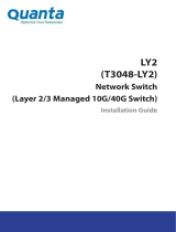
The ReadyRails kit consists of:
• Chassis rails that t on the left and right sides of a C9010 chassis (items 1 and 2 in Figure 10)
• Left and right rail brackets that t into the front rails on 2-post racks (items 3 and 4 in Figure 10)
• Front rails for the left and right posts of 2- and 4-post racks (items 5 and 6 in Figure 10)
• Rear rails that t into the left and right front rails on 4-post racks (items 7 and 8 in Figure 10)
• Two spacers that allow you to secure the chassis anges ush on the front rack posts (items 9 and 10 in Figure 10)
Installing the Hardware
17

Figure 10. Dell ReadyRails for 2- and 4-Post Racks
1
Left chassis rail 2 Right chassis rail
3 Left ReadyRail bracket for 2-post racks 4 Right ReadyRail bracket for 2-post racks
5 Left front rail with attached subassembly and thumb screw 6 Right front rail with attached subassembly and thumb screw
7 Rear rail that ts into the left front rail 8 Rear rail that ts into the right front rail
9 Left spacer 10 Right spacer
Tool-less Method for a Non-Threaded-Hole Rack
1 Attaching ReadyRails to the Rack
18
Installing the Hardware

a Remove the front and rear parts of the left 4-post rail from the Dell ReadyRails kit and slide the parts together. (The front and
rear parts of a rail may arrive pre-assembled.)
b Install a cage nut (item 2 in Figure 11) in the left front post at the desired height of the thumb screw on the left front rail.
c Install a cage nut in the left rear post at the same height as the cage nut in the left front post.
d Position the left rail so that the rail end labeled FRONT faces inward.
e Start with the rear left rail (item 3 in Figure 11); align the thumb screw with the cage nut and holes on the left rear post. Gently
press the rear rail end into the rack post and tighten the thumb screw in the cage nut to secure the rail to the post.
f Align the thumb screw on the front left rail with the cage nut (items 1 and 2 in Figure 11) inserted in the front post. Press the
front end of the rail forward and tighten the thumb screw so that it locks into the cage nut.
g Repeat Steps (a) through (f) to install the right rail.
h To remove or reposition a rail, loosen the thumb screw on each end and unseat the rail from the rack.
Figure 11. Installing Tool-less Rails in a Non-Threaded-Hole Rack
Installing the Hardware
19

2 Attaching the Chassis Rails
• Remove the two chassis rails from the Dell ReadyRails kit.
• Align the holes on the right and left chassis rails with the mounting studs at the bottom of each side of the chassis (orange arrows
and item 1 in Figure 12).
• Press each chassis rail over the studs and slide it backwards (towards the back of the chassis) so that it snaps securely into place
(blue arrows and item 2 in Figure 12).
Figure 12. Attaching the Chassis Rails
20
Installing the Hardware
/