CIAT CLIMACIAT AIRACCESS User manual
- Category
- Split-system air conditioners
- Type
- User manual
This manual is also suitable for

CLIMACIAT®
07 - 2023
EN7486825-09
Instruction manual

CONTENTS
1 - GENERAL INFORMATION ...................................................................................................................................................... 4
1.1 - Intended use........................................................................................................................................................................ 4
1.2 - Documentation .................................................................................................................................................................... 4
1.3 - Warranty .............................................................................................................................................................................. 4
2 - SAFETY INSTRUCTIONS ....................................................................................................................................................... 5
3 - REGULATIONS ....................................................................................................................................................................... 6
3.1 - General information ............................................................................................................................................................. 6
3.2 - Regulations ......................................................................................................................................................................... 6
3.3 - Accreditation ........................................................................................................................................................................ 7
3.4 - Pressure and temperature................................................................................................................................................... 7
4 - IDENTIFICATION ..................................................................................................................................................................... 8
4.1 - Data plate ............................................................................................................................................................................ 8
4.2 - Pictograms .......................................................................................................................................................................... 9
5 - SHIPPING - DELIVERY - HANDLING ................................................................................................................................... 10
5.1 - Shipping instructions ......................................................................................................................................................... 10
5.2 - Container shipment ........................................................................................................................................................... 10
5.3 - Delivery ............................................................................................................................................................................. 10
5.4 - Instructions for lifting and handling .....................................................................................................................................11
5.5 - Anchoring points for handling the block tted with transport feet ...................................................................................... 13
5.6 - Storage ............................................................................................................................................................................. 14
6 - INSTALLATION ..................................................................................................................................................................... 15
6.1 - Warning ............................................................................................................................................................................. 15
6.2 - Choise of location .............................................................................................................................................................. 15
6.3 - Assembling the blocks ....................................................................................................................................................... 19
6.4 - OPTIONS: Adjustable feet, risers and risers + cylinders ................................................................................................... 23
6.5 - JUXTAPOSE FUNCTION sealed junction special features .............................................................................................. 24
6.6 - Roof/canopy (Accessories) ............................................................................................................................................... 25
7 - CONNECTIONS ..................................................................................................................................................................... 32
7.1 - Condensate drain siphon .................................................................................................................................................. 32
7.2 - JUXTAPOSE function SPECIAL FEATURE. ................................................................................................................... 32
7.3 - Droplet eliminator .............................................................................................................................................................. 33
7.4 - Electric heater ................................................................................................................................................................... 35
7.5 - Connecting the disconnect switches/circuit breakers ........................................................................................................ 36
7.6 - Connecting the fans .......................................................................................................................................................... 37
7.7 - Filters................................................................................................................................................................................. 43
7.8 - Dierent lter locking systems: .......................................................................................................................................... 43
7.9 - Standalone steam humidier ............................................................................................................................................. 44
7.10 - Damper and mixing ......................................................................................................................................................... 45
7.11 - Heat recovery units .......................................................................................................................................................... 47
8 - CONTROL .............................................................................................................................................................................. 49
8.1 - AHU with control ................................................................................................................................................................ 49
8.2 - AHU without control ........................................................................................................................................................... 49
9 - COMMISSIONING ................................................................................................................................................................. 50
9.1 - Siphon ............................................................................................................................................................................... 50
9.2 - Pre-commissioning check ................................................................................................................................................. 50
9.3 - Filters................................................................................................................................................................................. 50
9.4 - Fan .................................................................................................................................................................................... 51
9.5 - Heating and Cooling coil ................................................................................................................................................... 53
9.6 - Electric heater ................................................................................................................................................................... 55
9.7 - Steam humidier ............................................................................................................................................................... 55
9.8 - Damper and mixing ........................................................................................................................................................... 56
9.9 - Heat recovery unit ............................................................................................................................................................. 57
9.10 - Check after start-up ......................................................................................................................................................... 60
CLIMACIAT® EN-2

CONTENTS
10 - OPERATION AND MAINTENANCE .................................................................................................................................... 62
10.1 - General recommendations for cleaning .......................................................................................................................... 62
10.2 - Filters............................................................................................................................................................................... 62
10.3 - Fans ................................................................................................................................................................................ 63
10.4 - Heating/cooling coil ......................................................................................................................................................... 64
10.5 - Electric heater ................................................................................................................................................................. 65
10.6 - Steam humidier ............................................................................................................................................................. 66
10.7 - Damper and mixing ......................................................................................................................................................... 66
10.8 - Sound attenuator ............................................................................................................................................................. 67
10.9 - Heat recovery units ........................................................................................................................................................ 67
10.10 - List of checks and maintenance .................................................................................................................................... 69
10.11 - Specic DIN1946-4 and VDI 6022 maintenance ........................................................................................................... 70
10.12 - Prolonged downtime...................................................................................................................................................... 70
11 - SPECIAL INFORMATION FOR ATEX AREAS ........................................................................................................... 71
11.1 - General information ......................................................................................................................................................... 71
11.2 - Labelling .......................................................................................................................................................................... 71
11.3 - System start-up, maintenance ......................................................................................................................................... 71
11.4 - Using tools in an explosive atmosphere .......................................................................................................................... 72
11.5 - Check - Periodic inspections ........................................................................................................................................... 73
11.6 - ATEX control sheet ......................................................................................................................................................... 74
12 - FINAL SHUTDOWN ............................................................................................................................................................. 75
12.1 - Shutting down.................................................................................................................................................................. 75
12.2 - Recommendations for disassembly ................................................................................................................................ 75
12.3 - Materials to be recovered for recycling ........................................................................................................................... 75
12.4 - Fluids to be recovered for recycling ................................................................................................................................ 75
12.5 - Waste electrical and electronic equipment (WEEE) ........................................................................................................ 75
Original document
EN-3 CLIMACIAT®

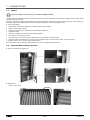
1 - GENERAL INFORMATION
■Thank you for choosing our air handling unit. The design and construction of your unit are the fruit of all the expertise oered
by our company's teams of technicians.
1.1 - Intended use
■The air handling units are designed for use indoors or outdoors (canopy and roof option mandatory)
■The units are intended to provide ventilation and, depending on the composition:
-Filtration of normal quality air,
-Filtration of air in sterile environments (special version for clean rooms),
-Air heating and/or cooling,
-Air humidication and/or dehumidication,
-Heat evacuation or recovery,
-Filtration and handling of particularly moist and/or contaminated air (special versions, e.g. for extracting air from swimming pools
or kitchens),
-Or a combination of the above characteristics.
■Any use other than that described above is deemed improper.
■If necessary, check whether your units are compatible with the applications for which you intend to use them.
■The manufacturer is not responsible for damage resulting from improper use.
■The user shall be held solely responsible.
■Your machine's specic operating conditions are set out in the contract review.
■The standard machine is designed to operate in urban and industrial environments with class C3 moderate pollution in accordance
with standard ISO 12944. Other options are available on request for more polluted environments or coastal areas.
The sharp increase in the air pressure when the re damper is closed may cause irreversible damage to the plate
heat exchangers.
Take into account the quality of the ambient air and the conditioned air.
1.2 - Documentation
■This manual contains all of the installation and operating instructions for your unit. This document must be read in full before
carrying out any work on the unit. This manual must be kept in the immediate vicinity of the unit. It does not cover the entire
installation.
■Please read all of the documents supplied with your order for information concerning the installation and system start-up steps.
■Depending on the options selected, specic handbooks may be included with this manual, and are also available from your
manufacturer. You should also read these handbooks before installing any options or carrying out any work (e.g. speed variator,
humidier, control, etc.),
■Devices installed and used in ATEX zones are marked with this symbol , A specic section of this manual is dedicated to the
limits of use and the precautions to be taken when installing, starting up and maintaining these devices. Refer to this section
before installing or carrying out any work.
1.3 - Warranty
■See general terms and conditions of sale.
■Any modication made to the unit by persons other than the manufacturer's employees, or without prior consent, shall result in
cancellation of the warranty.
CLIMACIAT® EN-4

2 - SAFETY INSTRUCTIONS
■The air handling units are designed in compliance with recognised safety rules.
■Unauthorised persons and the general public must be prevented from accessing this device.
■These units must be used in perfect condition and within their eld of application.
■Only qualied technicians may work on the machine. They must have all the necessary Personal Protective Equipment
(PPE): glasses, gloves, safety shoes, hearing protection, dust mask, etc.
■Check the following points before carrying out any work on the air handling unit.
-A 1 minute fan delay, no less, must be applied after the electric heaters and gas heating systems are shut down to allow
complete cooling. This delay must be adjusted as per the damper actioners rotary speed, but must not be less than 1
minute.
-Equipment lock-out in accordance with standard EN 60204/DIN VDE 0113.
-Warning: depending on the options selected, there may be several dierent power supplies on the various
units (main unit, supply unit for electric heaters, humidier), Make sure all power supplies are cut and locked
out.
-All moving or rotating parts must be shut down.
-Wait at least 15 minutes if using a frequency inverter (resultant voltage),
-All of the casings must be at atmospheric pressure before work can be carried out.
-Wait until the heat exchangers have cooled (heaters, steam, hot water coils),
-Make sure there are no foreign objects in the air handling units before starting them up.
■For units that can be entered, an "internal handle" option is available to prevent accidental entrapment.
During any servicing operations, all the recommendations and instructions given in the maintenance brochures, on the labels or
in the instructions accompanying the equipment must be observed, along with any other applicable safety instructions.
■Observe all the regulations in the safety codes.
■To prevent any risk of accident, prohibit public access by clearly marking the work area.
■Wear all the required Personal Protective Equipment (PPE),
■Follow the handling instructions.
■Handle heavy and bulky equipment with care when lifting, handling and setting down.
■Technicians who install, commission, operate and service the unit must understand the instructions given in this manual and be
familiar with the specic technical characteristics of the installation site.
For your safety, we recommend the use of PPE (Personal Protective Equipment)
PROTECTION AGAINST ELECTROCUTION
Only personnel qualied in accordance with the IEC (International Electrotechnical Commission) recommendations must be allowed
to access the electrical components. It is particularly recommended that all the electrical supplies to the unit are switched o before
any work is carried out. Cut the main power supply using the disconnect switch or circuit breaker.
The control system includes electronic components. These may cause or be subject to electromagnetic disturbance
if they are not installed and used in accordance with these instructions.
Before carrying out any work on the frequency inverters (heat recovery wheel, etc.), disconnect the power supply
and ensure that these are not live. After disconnection, you must wait 5 minutes before starting work (necessary
for the capacitors to discharge),
EN-5 CLIMACIAT®

3 - REGULATIONS
3.1 - General information
■Always follow and comply with the instructions in this manual and the regulations and legislation in force in the country of use.
■Any modications or welding to pressurised parts is dangerous and may be prohibited by regulations.
■The use of this equipment under seismic loads has not been veried.
■The units MUST NOT be stacked.
3.2 - Regulations
The manufacturer declares under its sole responsibility that this air handling unit, operating under the conditions provided for in
the product denition, complies with the provisions of the following directives and regulations.
It is up to the installer to carry out an additional risk analysis when integrating the equipment into its environment. For example, if
the equipment is not installed in a controlled area to which only authorized personnel have access - i.e. if a door can be opened
while the machine is running - then additional measures, such as the installation of our protection grid option, are required.
For any machine supplied without regulation, the installer assumes the manufacturer's obligations and must carry out a full risk
analysis. It is the installer's responsibility to ensure compliance of the machine with the control system supplied. We accept no
liability for any damage to persons and/or property resulting from inadequate safety or improper use. Some important recommendations
are listed in §8.2
Declaration of Conformity UE
This unit complies with the provisions of European Directives:
2006/42/EC (Machinery)
2014/30/EU (EMC)
2011/65/EU (RoHS)
2009/125/EC (Eco Design) and regulation 327/2011/EU & 1253/2014/EU
REGULATION (EC) No 1907/2006 (REACH)
UK Declaration of Conformity
This unit complies with the requirements of:
Supply of Machinery (Safety) Regulations 2008
Electromagnetic Compatibility Regulations 2016
The Restriction of the Use of Certain Hazardous Substances in Electrical and Electronic Equipment Regulations 2012
The Ecodesign for Energy-Related Products and Energy Information Regulations 2019, and following amendments
UK REACH Regulations 2019
UK Importer:
Toshiba Carrier UK Ltd, Porsham Close, Roborough, Plymouth, PL6 7DB
CLIMACIAT® EN-6

3.3 - Accreditation
■The following accreditation is required to work on the unit:
-Electrical qualication (in accordance with regulations) for working near the unit or on the electrical components.
■Technicians who install, commission, operate and service the unit must have received the necessary training and certication,
understand the instructions given in this manual and be familiar with the specic technical characteristics of the installation site.
■All work on the refrigerating circuit must comply with directive EC No. 842/2006.
3.4 - Pressure and temperature
■Maximum permissible pressures (OP):
-Water or glycol/water mix type heat exchanger: 8 bar.
-Superheated water type heat exchanger: 12 bar.
-Steam heat exchanger: 12 bar.
-Refrigeration heat exchangers: Group 2 refrigerants: 42 bar.
■Test pressure (TP): In accordance with § 5.3.2.2 a and 6.3.3 iii of standard 378-2, the pressure test (PT) is performed on model
representative of all 3 x PS assemblies.
■Transport temperature: -40°C/+75°C.
■Storage temperature: min.: -40°C, max.: +75°C.
■Operating temperature outside the air stream:
-Normal operation: min. -20°C, max. +50°C.
-Specic operation: min. -30°C, max. +75°C (consult the manufacturer),
■Operating temperature in the air stream:
-Normal operation: min. -20°C, max. +50°C.
-Specic operation: min. -30°C, max. +80°C (consult the manufacturer),
Our units are designed for altitudes of up to 1000 m. For higher altitudes, consult the manufacturer.
The altitude may signicantly aect the unit's performance due to the air density.
3 - REGULATIONS
EN-7 CLIMACIAT®

4 - IDENTIFICATION
4.1 - Data plate
■Each unit has a manufacturer's name plate bearing an identication number and the unit designation. Make sure this information
matches that on the order.
7xxx
TOTAL INTENSITE / CURRENT
Batterie Frigo
POIDS / WEIGHT SERVICE
Réf. Produit / Item Ref.
An / Year N. Serie : Serial Nbr
Batterie élec / Elec Heater
P.ABSORBEE / INPUT
Batterie Liq L2
Désignation / Description
Composant / Composant
Autres / Other parts
INTENSITE / CURRENT
Batterie vapeur G2
N° Déclaration CE
Repère / Part
BC
FED
G H I
J
■Data:
-Réf. Produit (Item ref.):
-Désignation (Description): Type.
-An (Year): Year of manufacture.
-N° série (Serial Nbr): Number to be quoted in all correspondence.
-Composant (Component):
-Repère (Part):
-Batterie élec / Elec Heater: if option chosen “3 50Hz 400V”
-Autres / Other parts: could be “3+N 50HZ 230/400V” or “3 50HZ 400V”
-TOTAL INTENSITE / CURRENT: if sum possible
-P.ABSORBEE / INPUT: Power input in W..
-INTENSITE / CURRENT:
-Batterie Frigo: if option chosen Fluid (type), Max temp., Pressure max adm.
-Batterie Liq L2: if option chosen 110C / 8BARS or similar
-Batterie vapeur G2 : if option chosen 150C / 12BARS or similar
-POIDS / WEIGHT SERVICE: Weight (in kg) of the unit in service.
-N° déclaration CE (EC declaration no.):
■ For the electrical consumption of humidiers and autonomous re detector, please refer to their own labels.
■ If the lighting option has been selected, a specic 230 V power supply is required.
■Markings (data plate, punch marks, labels) must remain visible. They must not be altered, removed or modied.
CLIMACIAT® EN-8

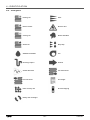
4.2 - Pictograms
Heating coil Filter
Electric heater Electrics box
Cooling coil Steam humidier
Steam coil Stop-drop
Adiabatic humidier Fan
Discharge siphon Air ow
Sound attenuator Coil outlet arrow
Coil inlet arrow Fire danger
Plate recovery unit Pressure tapping
Rotary heat exchanger
4 - IDENTIFICATION
EN-9 CLIMACIAT®

5 - SHIPPING - DELIVERY - HANDLING
5.1 - Shipping instructions
■Our units must be shipped in their original packaging and in the position in which they will be used.
-Blocks must not be stacked.
-Transshipment is not permitted.
■During shipping, the load must be lashed to the truck bed to prevent the unit
from moving and being damaged.
-Lashing must follow accepted industry practice, using straps made from
standardised synthetic bres (EN12195-2), clearly marked and labelled and
in perfect condition.
-Leave a space of at least 100 mm between the 2 units.
-Use anti-slip blocks under the unit's feet.
-We recommend top-over lashing. The straps must be tensioned manually,
enough to hold the equipment securely on the truck bed without damaging.
Do not use mechanical implements such as levers, bars, etc., unless the tensioning device is specially designed for use
with such implements.
5.2 - Container shipment
■The container dimensions must be adapted to those of the equipment being shipped.
■Slide the unit onto the container oor. When using a fork lift, place a spacer between the frame and the fork lift to prevent damage
to the unit's casing and accessories.
■The straps are fed through the lifting lugs on the frame to remove the unit from the container:
-Remove the unit from the container by pulling the 2 straps.
■Depending on the size and conguration, the units can be shipped in one or more blocks.
■Units supplied assembled on a frame:
-Steel mounts and pads, painted red, underneath the frame are used for removing the unit from the container and must be
removed before positioning it on site.
■Do not lift the unit by its accessories.
5.3 - Delivery
■Upon delivery of the unit components, inspect the consignment in the presence of the driver. If any damage is observed, or if
the delivery is incomplete, indicate this in the usual way on the delivery note and conrm to the carrier by registered letter within
three days of the delivery date and send a copy to us. Take photographs of any damage.
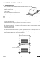
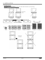
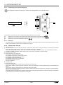
■Delivery of stacked blocks: in the case of an outdoor unit or with control option, the cable raceways are supplied not tted, and
can be found between the blocks on the upper panel (see image below),
Stacking of AHU_005 to 045
POSITION OF RACEWAYS
DURING SHIPPING
75° to 90°
CLIMACIAT® EN-10

WARNING: never use the terms "pending unwrapping" or "unit damaged, packaging intact", as these are not
admissible for insurance purposes.
For any other problem, your contact will be able to explain the relevant procedure.
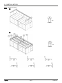
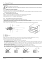
5.4 - Instructions for lifting and handling
■All of our units are supplied with lifting lugs.
■All lifting and handling operations must be carried out in accordance with the standards and regulations applicable to the handling
location and using standardised equipment.
■When handling, use lifting straps with a sucient lifting capacity. Do not use damaged straps. Use a lifting beam adapted to the
size of the unit to prevent the straps from exerting pressure on the unit, its accessories or the roof.
■When handling with a pallet truck or fork lift, make sure the forks are long enough to avoid damaging the casing. The forks must
project beyond the other side of the block.
The blocks must only be connected after handling and during installation.
It is forbidden to handle connected blocks unless they are fully supported by a suitable common structure.
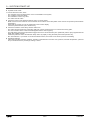
Lifting and handling a block
Lifting the unit on a packaged unit frame
■2 endless round slings:
■4 endless round slings:
5 - SHIPPING - DELIVERY - HANDLING
EN-11 CLIMACIAT®

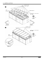
5.4.1 - SPECIAL FEATURE: STACKED plate heat exchanger THE AHU B P T060 T070
■The block is transported on its side. It must be lifted onto its feet before being handled with a crane.
■There is a risk that the block could become unstable during this operation.
■We recommend that you contact a lifting professional.
1 - LIFTING the block
■Refer to the documentation: LIFTING and HANDLING Sheet 1/2.
B
LIFTING
2 - HANDLING the block
■Refer to the documentation: LIFTING and HANDLING Sheet 2/2.
C
5 - SHIPPING - DELIVERY - HANDLING
CLIMACIAT® EN-12

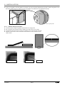
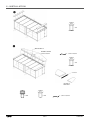
5.5 - Anchoring points for handling the block tted with transport feet
We recommend the use of shackles when handling these units.
75
60
Ø12.5
Ø35
47 28
37
5.5.1 - Special feature of CLIMACIAT® STAINLESS STEEL
THE steel threaded brackets (red eyebolt mounting) must be removed:
THREADED BRACKET
These lifting lugs are used when placing blocks near each other, AND MUST NOT BE USED ONCE DISASSEMBLED.
5 - SHIPPING - DELIVERY - HANDLING
EN-13 CLIMACIAT®

Packaged unit on a frame:
Ø35
50
5.6 - Storage
■Do not remove the original packaging.
■Do not remove the protective caps until you are ready to connect the coils.
■The unit must be stored on a at surface.
■Fit protection against shocks or impacts, which could damage the unit or its accessories.
■Store the blocks in their packaging, in a dry area sheltered from the weather.
■The ambient temperature must be between -10°C and 50°C.
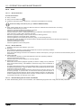
■To facilitate the assembly of multisplit units, their components must be kept in the relevant groups. Refer to the dimensional
drawings and marker labels on each block (see opposite),
G
C
J
B
H
D
I
E
F
K
B
Acknowledgement of receipt number
C
Block markings.
A1, A2, ….A9: multi-section unit.
A second unit will be marked B1, B2,…, B9.
The numbers 1, 2 and 3 do not necessarily indicate the order of assembly (refer to the dimensional drawing),
D
Internal production order = The serial number should be quoted in all correspondence.
E
Internal designation.
F
Customer name.
G
Pre-shipping internal inspection.
H
Customer reference.
I
Weight of corresponding block.
J
Block year of manufacture.
K
Manufacturer's name and address.
5 - SHIPPING - DELIVERY - HANDLING
CLIMACIAT® EN-14

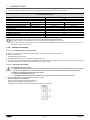
6 - INSTALLATION
6.1 - Warning
The installation of equipment must comply with the regulations in force at the installation site. Before installing, make sure that the
components are clean, and clean them if necessary.
Follow the safety instructions (see § 2 - SAFETY INSTRUCTIONS),
6.2 - Choise of location
■Before setting up and connecting the unit, the installer must check the following points:
-The unit's earthquake resistance has not been veried.
-These units can be placed directly on at, level ground. The atness value must be the best possible, around one per
thousand.
-For outdoor installation, take into account the regulations in force and the weather conditions at the installation site (risk
of snow, height from the ground, risk of wind, etc.),
-The selected location must not be liable to ooding.
-Raise the unit to ensure that the unit's operation is not aected by a buildup of snow.
-Take into account the required height of the siphon, the slope and the length of the condensate drainage container.
-There are three support options:
• ADJUSTABLE FEET
• RISERS
• RISERS + CYLINDERS (Specications section 6.4)
-The unit must be perfectly level (see diagram in § 6.3 Assembling the blocks),
-The surface of the ground or structure must be strong enough to bear the unit's weight.
-For outdoor installation with no weather protection, the unit must be equipped with the roof option. Make sure this option
is tted.
-Leave sucient space around and above the unit for servicing and maintenance operations (see dimensional drawing),
Take into account the space required to open the doors.
-Leave space equivalent to the total depth of the unit on the utilities side to allow internal components to be removed.
See dimensional drawing.
-Under normal indoor conditions of use, there is no need to x the unit to the oor.
-Under outdoor installation conditions, the unit must be xed to the oor (windproong),
■Depending on the regulations in force in the storage and installation location, precautions must be taken, particularly for roof
installation, to ensure that the unit is stable (strong winds, earthquake, etc.), This may involve mounting on the ground or the
support frame.
-For indoor installation, the room must conform to the regulations in force at the installation site. In particular, if the unit is equipped
with a thermodynamic system, the room must conform to standard EN 378-3 or other specications governing the installation
location (outside EC),
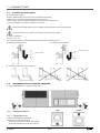
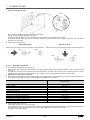
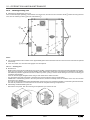
-Connections must not place mechanical stresses on the unit.
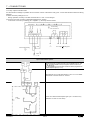
-When connecting directly to the unit, the hydraulic pipes and air ducts must be held using supports close to their point of
connection on the unit (Fig. 1),
Flexible sleeve
Duct
suspensions
Duct
bracket
Fig. 1 Fig. 2
Support
-The hydraulic control valve kits must be supported close to their point of connection on the unit (Fig. 2)
-No connection should obstruct the unit's access doors, hatches or drawers.
■Dual-ow units should be installed so as to prevent direct recirculation between the discharge and intake nozzles.
■For installation in very dusty environments or areas with high pollen levels, we recommend a system of pre-lters on the fresh
air intake. The air inlets should be positioned so as to minimise adverse eects on the quality of air entering close to local
emissions, such as discharge air, radon, odours or other disruptive sources (road trac, garage doors, car parks and buses,
tarmac, human impacts, animals, whether dead or alive)
EN-15 CLIMACIAT®

■Freezing fog can very quickly block the fresh air inlet lters. Fit an air preheating system (option available) for temperatures
between approximately +3°C and -3°C.
■For units equipped with a gas heater (GGS or Make-Up type), the gas connection must be made by qualied personnel in
accordance with the regulations in force at the installation site.
Sound level
■Our units are designed to operate quietly.
■As soon as you begin designing your system, you should take into consideration the outdoor environment to estimate the radiated
noise, and the building type for the noise transmitted through the air and by solid materials.
■To minimise solid-borne vibrations, we recommend tting anti-vibration mounts between the unit's support and frame (see
diagram below), exible connectors on the hydraulic pipes and exible sleeves on the ducts.
Have an analysis carried out by an acoustical engineer.
For units supplied in separate elements, a counter frame must be used to add anti-vibration mounts (Fig. 1) (Frame and mounts
supplied by the customer),
Fig. 1
Firebreak:
Fire can spread between the supply and the return (e.g. through the heat recovery system or the mixing air),
Fit the mandatory safety devices based on the regulations in force at the installation site (e.g. re dampers),
6 - INSTALLATION
CLIMACIAT® EN-16

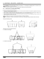
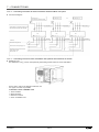
6.2.1 - INSTALLATION Stacking conditions
STACKING SINGLE-FLOW UNITS
■IDENTICAL WIDTH:
-Option to stack two units of identical width: Fig. 1
-ANTI-VIBRATION MOUNTS* (For a noise level study)
A COUNTER FRAME must be tted*: Fig. 2
Sizes 060 and 070 anti-vibration mounts PROHIBITED: Fig. 3
* Not supplied
870
560
860
1460
005 010 015 020 025 035 045 060 070
870 1130 1470 1840 1840 2070 2070 2340
Fig.1
STACKING AUTHORISED STACKING AUTHORISED
Fig.2 Fig.3
Sound level study
COUNTER FRAME*
INTERMEDIATE FRAME
and ANTI-VIBRATION
MOUNTS BETWEEN FLOW
> PROHIBITED
ANTI-VIBRATION
MOUNTS *
Single-ow blocks at the top which are not fully supported on the unit must be supported by a suitable device*
BRACKET*
Example (identical to Fig. 2) of stacked units
Openings front view
Anti-vibration mounts and counter frame tted to ensure uniform load distribution
LEVELLING ESSENTIAL
To ensure correct sealing between
the blocks
6 - INSTALLATION
EN-17 CLIMACIAT®

6 - INSTALLATION
■DIFFERENT WIDTHS:
-To stack two units of dierent widths
-AN INTERMEDIATE FRAME MUST BE FITTED* of the same width as the lower unit. (Load lowering)
* Not supplied
STACKING NOT
AUTHORISED
STACKING
AUTHORISED
INTERMEDIATE
FRAME*
STACKING NOT
AUTHORISED
IT IS FORBIDDEN TO STACK PACKAGED DUAL-FLOW UNITS (Sizes 005 to 045)
870
1120
1120
2160
3000
870 1130 1470 1840 1840 2070 2070 2340
005 010 015 020
Dual-ow PACKAGED Dual-ow BIBLOC
025 035 045 060 070
STACKING NOT
AUTHORISED
CLIMACIAT® EN-18

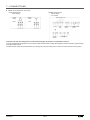
6.3 - Assembling the blocks
Ensure sucient servicing space to allow easy maintenance and assembly of the blocks.
The blocks must be assembled according to the instructions in this manual. The air inlets must be plugged if assembly is interrupted.
A waterproof lm is recommended to prevent white rust.
Electrical safety
The components and cables must be selected in accordance with the regulations in force at the installation site.
Always comply with the overvoltage, pollution and insulation voltage categories set by the standards and regulations.
Take into account the altitude when selecting the components and cables
Reminder: For units delivered unregulated and installed in CE zones, CE certication for the complete assembled unit is
the responsibility of the person assembling it.
Make sure the ground is at for the purposes of installing the unit and connecting the blocks.
To ensure a tight seal between joined sections, they must be shimmed and levelled to compensate for any unevenness
of the mounting surface.
0 + 0.3°
0 + 0.3°
Air
ow
direction
Levels
The unit must be grounded via its frame. Make sure all electric components are grounded.
■The units are supplied with transport feet
B
.
They must be removed and possibly replaced with adjustable feet or risers before nal assembly. (see § 6.4),
B
■Ax the cleats (2) supplied in the connection kit (g.A) in the dedicated holes using long screws 4.8 x 40 mm (5) in each block.
Fig. A
B
C
C
D
E
F
F
6 - INSTALLATION
EN-19 CLIMACIAT®

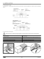
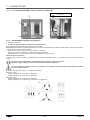
■Fit the 15 x 9 gasket on the end partition of one block. To ensure a proper seal between two blocks, position the gasket on the
aluminium proled edge of one block as close as possible to the inside of the unit (illustrations below),
DETAIL: gasket position
Gasket
Gasket
6.3.1 - Gasket removal procedure:
■To ensure proper sealing, the gasket must be tted as a single piece.
■The connection must be at the bottom, ideally in the centre, but not in a corner.
■To guarantee optimal long-term integrity, the gasket must not be removed when taut.
■Likewise in the corners, it must not be taut, but should form a rim inside the corner.
Sketch below:
Compliant RimNon-compliant
Do not tension the gasket
6 - INSTALLATION
CLIMACIAT® EN-20
Page is loading ...
Page is loading ...
Page is loading ...
Page is loading ...
Page is loading ...
Page is loading ...
Page is loading ...
Page is loading ...
Page is loading ...
Page is loading ...
Page is loading ...
Page is loading ...
Page is loading ...
Page is loading ...
Page is loading ...
Page is loading ...
Page is loading ...
Page is loading ...
Page is loading ...
Page is loading ...
Page is loading ...
Page is loading ...
Page is loading ...
Page is loading ...
Page is loading ...
Page is loading ...
Page is loading ...
Page is loading ...
Page is loading ...
Page is loading ...
Page is loading ...
Page is loading ...
Page is loading ...
Page is loading ...
Page is loading ...
Page is loading ...
Page is loading ...
Page is loading ...
Page is loading ...
Page is loading ...
Page is loading ...
Page is loading ...
Page is loading ...
Page is loading ...
Page is loading ...
Page is loading ...
Page is loading ...
Page is loading ...
Page is loading ...
Page is loading ...
Page is loading ...
Page is loading ...
Page is loading ...
Page is loading ...
Page is loading ...
Page is loading ...
-
 1
1
-
 2
2
-
 3
3
-
 4
4
-
 5
5
-
 6
6
-
 7
7
-
 8
8
-
 9
9
-
 10
10
-
 11
11
-
 12
12
-
 13
13
-
 14
14
-
 15
15
-
 16
16
-
 17
17
-
 18
18
-
 19
19
-
 20
20
-
 21
21
-
 22
22
-
 23
23
-
 24
24
-
 25
25
-
 26
26
-
 27
27
-
 28
28
-
 29
29
-
 30
30
-
 31
31
-
 32
32
-
 33
33
-
 34
34
-
 35
35
-
 36
36
-
 37
37
-
 38
38
-
 39
39
-
 40
40
-
 41
41
-
 42
42
-
 43
43
-
 44
44
-
 45
45
-
 46
46
-
 47
47
-
 48
48
-
 49
49
-
 50
50
-
 51
51
-
 52
52
-
 53
53
-
 54
54
-
 55
55
-
 56
56
-
 57
57
-
 58
58
-
 59
59
-
 60
60
-
 61
61
-
 62
62
-
 63
63
-
 64
64
-
 65
65
-
 66
66
-
 67
67
-
 68
68
-
 69
69
-
 70
70
-
 71
71
-
 72
72
-
 73
73
-
 74
74
-
 75
75
-
 76
76


CIAT CLIMACIAT AIRACCESS User manual
- Category
- Split-system air conditioners
- Type
- User manual
- This manual is also suitable for
Ask a question and I''ll find the answer in the document
Finding information in a document is now easier with AI
Related papers
Other documents
-
Trox X-CUBE Installation guide
-
-
Wolf AHU TE Installation And Maintenance Instructions Manual
-
FläktGroup EQRO Rotary heat exchanger Installation and Maintenance Manual
-
-
 MOUNTUP MU9007 Installation guide
-
Trane Performance Climate Changer PSCA Installation, Operation and Maintenance Manual
-
-
-
