Wirepath WPS-550-DOM-IP-BL Owner's manual
- Category
- Security cameras
- Type
- Owner's manual
This manual is also suitable for

CAMERA
IP DOME
INSTALLATION MANUAL
Review manual thoroughly before installation.
Retain for future reference.
WPS-550-DOM-IP

2
WPS-550-DOM-IP Installation Manual
1. Safety Instructions
1. Read and follow all instructions and warnings in this manual. Keep for future reference.
2. Install according to manufacturer’s instructions.
3. Do not install near any heat sources such as radiators, heat registers, stoves or other apparatus (including ampliers)
that produce heat.
4. Only use attachments/accessories specied by the manufacturer.
5. Refer all servicing to qualied service personnel. Servicing is required when the apparatus has been damaged in any
way, such as when the power-supply cord or plug is damaged, does not operate normally, or has been dropped.
6. THE MAINS PLUG OF THE POWER SUPPLY CORD SHALL REMAIN READILY OPERABLE.
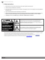
CAUTION
CAUTION: TO REDUCE THE RISK OF
ELECTRICAL SHOCK.
DO NOT REMOVE COVER. NO USER
SERVICEABLE PARTS INSIDE.
REFER SERVICING TO QUALIFIED
SERVICE PERSONNEL.
The lightning ash with arrowhead symbol, within an equilateral triangle,
is intended to alert the user to the presence of uninsulated dangerous
voltage within the product’s enclosure that may be of sufcient magnitude to
constitute a risk of electric shock to persons.
The exclamation point within an equilateral triangle is intended to alert the
user to the presence of important operating and maintenance (servicing)
instructions in the literature accompanying the appliance.
When viewing this document electronically, references to other sections are formatted to stand out. Click on a reference to navigate
to the section. Table of Contents entries may also be clicked to link to sections for faster navigation.
Example: (Cross-reference in one section to another part of the manual) For more information see section 2. Introduction.
Example: (Hyperlink to a website, will open in a new browser window) Go to www.SnapAV.com.
Color warning images,
add one for notes since
we have those through
out the manual

3
© 2014 Wirepath Surveillance
WPS-550-DOM-IP Installation Manual
Table of Contents
1. Safety Instructions 2
2. Introduction 7
2.1. Features 7
3. Package Contents 8
4. Required Items for Installation 8
5. How It Works 9
6. Camera Connections 10
6.1. Network Cable Recommendation (PoE and non-PoE) 10
6.2. Choosing the Right Network Equipment 10
6.3. PoE Requirements- IEEE 802.3af 10
7. Camera Installation Instructions 11
7.1. Wiring Installation 11
7.2. Camera Mounting 11
7.3. Aiming the Camera 12
7.4. Closing the Camera Dome 12
7.5. Network Software Setup - IP Installer 13
7.5.1. Running the IP Installer 13
7.6. IP Installer-Conguring Camera IP Settings 14
7.7. Verify Access through the Main Camera Interface 14
8. IP Camera Web Interface - Setup and Use 15
8.1. First Time Access Instructions 15
8.1.1. Recommendations for Best Web Viewing Performance 15
8.2. Camera Web Browser Interface 16
8.2.1. Web Interface Layout - Top Bar 16
8.2.2. Web Interface Layout - Bottom Bar 17
9. Camera Conguration Menu Setup 18
9.1. Conguration Menu - Access and Navigation 18
9.1.1. Accessing the Menu 18
9.1.2. Conguration Menu Layout 18
9.1.3. Conguration Menu Guidelines 18
9.2. System Information and Settings 19

4
WPS-550-DOM-IP Installation Manual
9.2.1. System Information Menu Settings 19
9.2.1.1. Server Information 19
9.2.1.2. OSD Setting 19
9.2.1.3. Time Setting 20
9.2.1.4. Network LED 20
9.2.2. Camera Time Setup 21
9.2.2.1. NTP Time 21
9.2.2.2. Synchronize With PC’s Time 21
9.2.2.3. Manual 21
9.2.2.4. Internal Clock 21
9.2.2.5. NTP Setup Instructions (For Cameras with Internet Access) 22
9.2.2.6. Time Setup for Cameras Without Internet Access 22
9.2.3. User Management 23
9.2.3.1. Anonymous User Login 23
9.2.3.2. Add User (Guest Account only) 23
9.2.3.3. User List 23
9.2.3.4. User Account Levels 23
9.2.3.5. Administrator Account Setup 24
9.2.3.6. Add, Edit, or Remove a Guest Account 24
9.2.4. System Update 25
9.2.4.1. Firmware Upgrade 25
9.2.4.2. Reboot System 25
9.2.4.3. Setting Management 25
9.2.4.4. How To Back Up Camera Settings 26
9.2.4.5. Load Backup Settings to the Camera 26
9.2.4.6. Upgrade the Firmware 27
9.3. Network IP Settings 28
9.3.1. Basic IP Settings 28
9.3.1.1. IP Assignment 28
9.3.1.2. Port Assignment 29
9.3.1.3. UPnP 29
9.3.1.4. RTSP Setting 30
9.3.1.5. Multicast Setting (Based on RTSP Server) 30
9.3.1.6. ONVIF 31
9.3.1.7. Bonjour 31
9.3.1.8. Link Layer Topological Discovery (LLTD) 31
9.3.2. Advanced IP Settings - HTTPS Access Setup 32
9.3.2.1. Created Request 32
9.3.2.2. Installed Certicate 32
9.3.2.3. Connection Types 32
9.3.3. Advanced IP Settings - SNMP 33
9.3.4. Advanced IP Settings - Access List (IP Filter) 34
9.3.4.1. IP Address Filter Setting 34
9.3.4.2. Add or Remove IP Addresses or Ranges 35
9.3.4.3. Controlling Administrator Access 35
9.3.5. Advanced IP Settings - QoS/DSCP 36
9.3.5.1. QoS / DSCP Setting 36

5
© 2014 Wirepath Surveillance
WPS-550-DOM-IP Installation Manual
9.3.6. PPPoE Setup 37
9.3.6.1. PPPoE Overview 37
9.3.6.2. PPPoE Settings 37
9.3.6.3. Send Mail after PPoE Dialed 37
9.3.7. DDNS Setup 38
9.3.7.1. DDNS Overview 38
9.3.7.2. DDNS Settings 38
9.3.7.3. State (DDNS) 38
9.3.7.4. Setting Up a DDNS Address – WirepathDNS 39
9.3.8. Server Settings 40
9.3.8.1. Email Notications 40
9.3.8.2. Mail Settings 40
9.3.8.3. FTP Settings 41
9.3.8.4. Network Share Settings 42
9.4. Camera A/V Settings 43
9.4.1. Image Settings Menu 43
9.4.1.1. Tips for Getting the Best Camera Image 44
9.4.2. How to Congure Day and Night Settings (Color Modes) 44
9.4.2.1. Day & Night Modes 44
9.4.2.2. EXT Light Sensor Mode (Default Mode) 45
9.4.2.3. Time Mode Setup 45
9.4.2.4. How To Congure Privacy Masks 46
9.4.3. Video Settings Menu Overview 47
9.4.3.1. Video Setting (For BNC Test Adapter Output) 47
9.4.3.2. Streaming 1 and 2 Setting 47
9.4.3.3. Streaming 3 (JPG/MJPEG) 47
9.4.3.4. Streaming 4 (3GPP) 47
9.4.4. Video Streaming 1 and 2 Setup 48
9.4.5. Streaming 3 and 4 Setup 49
9.4.5.1. Streaming 3 49
9.4.5.2. Streaming 4 49
9.5. Event Record Setup and Scheduling 50
9.5.1. Event Settings Menu 50
9.5.1.1. Record File 51
9.5.1.2. Record Time Setting 51
9.5.1.3. Network Disconnected 51
9.5.1.4. Network IP Check 51
9.5.2. Conguring Motion Detection Areas 52
9.5.2.1. Motion Detection Settings Overview 52
9.5.2.2. Adding a New Motion Detection Area 53
9.5.2.3. Removing a Motion Detection Area 53
9.5.3. Schedule Menu 54
9.5.3.1. Snapshot Menu 54
9.5.3.2. How to Set Up Scheduling for Events 55
9.5.3.3. Set up Snapshot 55

6
WPS-550-DOM-IP Installation Manual
9.6. Log List 56
9.6.3.1. System Log 56
9.6.3.2. Motion Detection Log 56
9.6.3.3. All Logs 56
9.7. SD Card Menu 57
9.7.1. Playback 57
9.7.2. SD Management 57
10. Mobile App Access 58
10.1. Reset Procedure 58
11. Specications 59
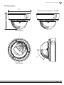
12. Dimensions 61
13. Warranty 62
14. Contacting Technical Support 62

7
© 2014 Wirepath Surveillance
WPS-550-DOM-IP Installation Manual
2. Introduction
Thank you for purchasing a Wirepath™ IP Surveillance camera. The WPS-550-DOM-IP is an indoor/outdoor camera designed for
mounting to any wall, ceiling or surface, for easy monitoring over a web or smartphone interface.
We recommend that this document be read in its entirety before proceeding with system design, installation, or operation of the
camera.
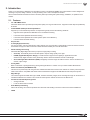
2.1. Features
• 1/4” 1MP CMOS Sensor
Advanced CMOS sensor provides improved picture quality over a typical CCD sensor. Supports full Full 720p HD (1280x720)
at 30FPS.
• H.264/ MJPEG Quadruple Stream Optimization
Supports up to 4 simultaneously streams of compression typically used for the following situations:
• High Res stream optimized for NVR Record or Local Network viewing
• Lower Res stream optimized for Remote viewing
• Lower Res stream optimized for Control Systems (same res as Stream 2)
• Low Res stream for Mobile Viewing
• IR up to 50 ft
• True Day/Night (IR Cut Filter)
For more accurate, vivid color reproduction during daytime use, an IR Cut lter is automatically moved over the lens to block
unwanted IR. At night, the lter is removed to deliver maximum visibility and clear IR illumination.
• Advanced Image Processing
Advanced DSP (Digital Signal Processor) to improve image quality including:
• Sense Up: Automatically slows the shutter speed to improve image quality in low light.
• D-WDR (Digital Wide Dynamic Range): Provides clearer images and even lighting in applications that are
simultaneously bright and dark. This is particularly useful in areas with windows and lots of natural light.
• 2D and 3D Digital Noise Reduction (DNR): Intelligently scans the image and reduces noise in low-lux conditions for a
cleaner, crisper image.
• Privacy Mask
Block out sensitive or privileged areas by placing rectangular blocks or “masks” over up to three installer-dened areas.
• Power Over Ethernet (PoE IEEE 802.3af)
Camera can be powered by PoE using the same Cat5e/Cat6 cable that connects to the network. No need to pull a 2nd power
cable to the location. Compatible with all PoE network switches that support PoE IEEE 802.3af and PoE power injectors.
• Edge Storage
The camera supports microSD cards (up to 32GB, card NOT included). Images, short recordings and logs can be stored on a
microSD installed into the camera. This is useful as a backup if the network connection to the NVR is lost.
• Test Port for Quick Setup during Install
• Analog Video Out
• Local 12V DC Power for Camera
• IP-66 Weatherproof Rating
With an IP-66 rating, this camera is protected from dust and water making it at home in indoor and outdoor installations.
• ONVIF

8
WPS-550-DOM-IP Installation Manual
3. Package Contents
NOTE: A POWER SUPPLY IS NOT INCLUDED WITH THIS CAMERA. The PS-12DC-1A, WPS-PS multiple output power supply
or a Power over Ethernet (PoE) switch is recommended.
4. Required Items for Installation
The following items are required during the installation of a Wirepath™ IP camera. Prepare all parts and tools in advance to ensure
that the installation can be performed smoothly.
• Local Ethernet network installed
• All cameras to be installed in the system
• PoE Ethernet equipment or power supplies and wiring to power cameras
• Network connection at each camera location
• Access to a PC connected to the local network
• Static IP address to assign to the camera
• Additional access information for network equipment:
• Router / Switch Details – Contact the network admin to obtain access to equipment settings.
• Admin Rights – Required to setup the network and port forwarding for remote access.
• Default Gateway
• Subnet Mask
• DNS Address
• Recommended for mounting cameras and wiring:
• Hand tools
• Drill (May be needed for mounting the camera)
• Extra connectors for terminating cables on the job
• (1) WPS-550-DOM-IP Camera
• (1) WPS-ACC-PWR Power Adapter
• (1) Female to Female RJ45 Adapter
• (1) 3mm Allen key
• (4) Screws
• (4) Wall Fasteners
• (1) Spare Silica Pack
• (1) Quick Start Guide

9
© 2014 Wirepath Surveillance
WPS-550-DOM-IP Installation Manual
How Does IP Video Surveillance Work?
Wirepath™ IP cameras use a digital image processor to capture video in a stream of packets that are broadcast using a standard
Ethernet network. These packets can be received by several devices at once, including local PCs, mobile devices, and recorders
(NVRs) on the same network, or even off the network (with the correct setup and web access).
Users can see the camera feed through the interface of their choice, or see recorded footage from a storage device like an NVR.
Wirepath Surveillance offers apps for iOS
®
devices, Android
®
smartphones, Windows PC, and Mac computers. Drivers for various
popular control systems are also available for integration with a control system.
Access and Use
For local network (LAN) access, a static IP address is assigned to the camera in the network router. The user enters this address
into a PC, smartphone, or other device connected to the LAN, and logs in using a customizable user name and password.
For access outside the LAN, a port is forwarded to the camera in the network router settings and a DDNS address is set up in the
camera. This enables the same streams from the camera to be broadcast anywhere in the world over an Internet connection.
In systems where the camera stream must be recorded, a network video recorder (NVR) is connected to the LAN. The address and
login credentials for the camera are entered and the stream can be captured as needed for later viewing.
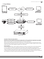
5. How It Works
Streaming audio/
video
Access from IP
interface
Power from PoE or
Power Supply
WPS-IP Mobile App
Streaming
Browser Interface
Streaming, Setup
Browser Interface
Streaming, Setup
Video streams to
NVR for recording
Port Forwarding and DDNS allows camera to be
accessed from the Internet
Gigabit Router and Switch
Wirepath™ NVR
LAN-Based Computer
Smartphone/Tablet
Web-Based Computer

10
WPS-550-DOM-IP Installation Manual
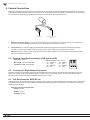
6. Camera Connections
Wirepath™ Surveillance IP Cameras can be powered by Power over Ethernet (PoE) through the Cat5e/Cat6 Ethernet connection.
This method is recommended because it limits the amount of wiring required, reducing installation cost and time. The camera must
be connected to a compatible PoE-equipped router/switch or a PoE injector for this method to work.
2. 12V DC Power In
(Black)
1. Ethernet
1. Ethernet Connection (RJ45) — Connect to network switch for communication to and from the camera. If the network port
supports PoE standard IEEE 802.3af then power can be provided on the Cat5e/6 connection.
2. 12V DC Power In — No power supply is needed if PoE is being used to power the camera via the Ethernet connection.
Connect to a 12V DC power supply if PoE is not being used. A power supply is not included with the camera.
Warning! Use only a 12V DC power supply with this camera. Higher voltages or AC current will cause permanent damage
that is not covered by the warranty.
6.1. Network Cable Recommendation (PoE and non-PoE)
• Cable Type: Cat5e/6
• Max Length: 100 meters (328 feet)
• Termination: 568B recommended
6.2. Choosing the Right Network Equipment
Streaming content from IP Cameras requires more bandwidth than most IP devices. We recommend using 1Gbps routers and
switches to maintain a high quality streaming image. To reduce trafc on the overall network, we also recommend that all IP
Surveillance devices be connected to a dedicated 1Gbps switch or VLAN.
6.3. PoE Requirements- IEEE 802.3af
Cameras must be connected to a PoE injector (inline PoE power supply) or a PoE-equipped port of a network router or switch built
to IEEE 802.3af standards. Consider installing a dedicated PoE switch specically for IP cameras on the network to avoid issues
relating to power shortage.
• Minimum requirement for PoE ports:
• Voltage: 44V DC
• Wattage: 15.4W
• Amperage: 350mA
Pin 1 White/Orange Pin 5 White/Blue
Pin 2 Orange Pin 6 Green
Pin 3 White/Green Pin 7 White/Brown
Pin 4 Blue Pin 8 Brown
TIA/EIA Standard 568-B (Gold Pins Facing Up)

11
© 2014 Wirepath Surveillance
WPS-550-DOM-IP Installation Manual
7. Camera Installation Instructions
7.1. Wiring Installation
A. Run a Cat5e/6 cable from the network port to the camera location and terminate both ends to 568B.
B. (Non-PoE applications only) Run wiring to the camera from the power supply location. Use the voltage drop calculator at www.
SnapAV.com to determine the wire size needed.
C. (Non-PoE applications only) Connect the power supply to the wire at the head end using electrical connectors (not included),
and attach the WPS-ACC-PWR-M to the wire at the camera location. Be sure to use the correct polarity.
D. (Non-PoE applications only) Connect the power supply to a suitable outlet and test the voltage at the camera side of the wire
using a volt meter. Disconnect the power supply from the outlet until camera installation is otherwise complete.
7.2. Camera Mounting
Important Note: To avoid damaging the dome surface during installation, keep the dome surface away from walls and other
objects. Do not remove the protective lm from the dome until after the camera is mounted and the dome installed.
A. Unpack the camera and open the dome. Do not remove the protective lm from
the dome.
B. If the camera is going to be surface mounted, use the provided foam gasket as
a template to mark 3 mounting hole locations, and then make pilot holes for the
screws. If a mounting accessory is being used, install the accessory over the
wiring according to the included instructions.
C. Attach the foam gasket to the bottom of the camera base. Pull the cable through
the side of the housing knockout if needed.
D. Connect the wiring to the camera, then push the wiring into the box or cavity
behind the camera.
E. Secure the camera to the accessory or surface using 3 screws.
F. Install a microSD card in the slot if desired.
microSD Card Slot
G. Pull the test adapter from inside the dome housing if needed for attaching a test
monitor and power supply.

12
WPS-550-DOM-IP Installation Manual
7.3. Aiming the Camera
A. Connect the BNC Test Adapter to a monitor or WPS-CCTV-TESTER video in.
B. Connect a power supply to the secondary power connection on the camera (if main power connection is not active).
C. Adjust the camera’s 3-axis angle so the lens points in the desired direction.
Warning: The lens angle must not exceed 67˚ off the center axis. This will prevent IR reection inside the dome from causing a
halo effect in the camera image at night.
Maximum Camera Angle
67.0°
67.0°
D. Disconnect the WPS-CCTV-TESTER or monitor and power supply from the local test connections and push them back into the
housing.
7.4. Closing the Camera Dome
Recommendation: Before replacing the dome we recommend that a new silica gel pack be inserted into the camera to ensure that
any moisture present will be removed.
A. Ensure that the lens gasket is properly tted to the lens assembly.
B. Replace the dome cover to the dome base, and make sure the screws on the dome cover are tightened securely.
C. Remove the warning sticker and protective lm.
Warning: The dome must provide a tight t around the rubber lens gasket to avoid IR reection off of the dome resulting in a halo
effect in the camera image at night.
Lens Rubber Gasket

13
© 2014 Wirepath Surveillance
WPS-550-DOM-IP Installation Manual
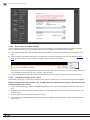
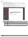
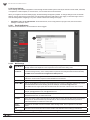
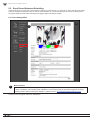
7.5. Network Software Setup - IP Installer
The IP Installer software included with the camera provides a quick view of Wirepath™ IP Surveillance devices connected to the
local network. Use the Installer to search for and set basic IP settings for each camera.
Before starting any conguration or service of Wirepath™ IP devices, we recommend checking for a newer version of the IP
Installer on the camera’s support tab at www.SnapAV.com.
Important! Active VPN connections anywhere on the network will prevent the IP Installer from working correctly. Close all
VPN connections before running the Installer.
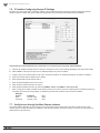
7.5.1. Running the IP Installer
A. The IP Installer EXE le can be downloaded from the camera’s support tab at www.SnapAV.com. No installation is required for
use. Extract the le from the ZIP le (if compressed) and move it to the Desktop or folder of your choice.
B. Run the software. Windows may attempt to block the action. If this occurs, allow the software to run. No changes will be made
to Windows or other system les. It may be necessary to log in as or provide the administrator account password for the PC for
the IP Installer to run.
C. When it opens, the installer automatically scans the network for any connected Wirepath™ IP Cameras, NVRs, and Encoders.
Click “Search Devices” to rescan the network if more devices are added and make changes to camera settings as needed.
D. Click the “X” at the top right corner or the “Exit” button to close the IP installer when all devices are congured. Windows may
display an error that the software did not install correctly when it closes but this should be disregarded.
Device List displays
connected devices on
the network.
Click a device name to
make changes in the
right column.
Double-click a device
name to load the IP
interface using your web
browser.
Right column shows
current IP settings for
the highlighted device.
Click Search Device to
refresh the Device List.
Change settings by
updating the elds and
then clicking “Submit”.

14
WPS-550-DOM-IP Installation Manual
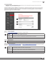
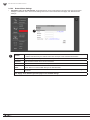
7.6. IP Installer-Conguring Camera IP Settings
By default, the camera will receive a DHCP IP address. This should be changed to a reserved or static IP address so that the
camera remains accessible after setup. Obtain the settings below from the network administrator before installation.
Consult with the router manufacturer for instructions to correctly set up a reserved or static IP address.
A. Open the IP Installer and single-click on a camera in the Device List. Its current settings will appear in the right column elds.
B. Select “Static” at the top of the right column. Network settings may now be modied.
C. Assign a name to the camera based on the scene or location (Limited to 31 characters) Examples: FrontDoor1, SideDoor...
D. Enter the reserved static IP address for the camera.
E. Enter the Net Mask (usually 255.255.255.0).
F. Enter the default Gateway (found in the router).
G. Enter the DNS 1 address (found in the router).
H. Enter the DNS 2 address (found in the router). Set DNS 2 “0.0.0.0” if no DNS 2 is set in the router.
I. Enter a unique port number to enable remote Internet access to the camera. Use port numbering that is consistent and easy to
remember. We recommend using 4 digits, “8” followed by the last three numbers of the camera’s IP address.
Examples:
Camera IP Address Port
Patio 192.168.1.050 8050
Front Door 192.168.1.100 8051
7.7. Verify Access through the Main Camera Interface
Once the IP address has been set, the camera can be accessed through the web browser. Note that on initial access to each
camera, Active X controls will need to be installed on each PC that is used to access the camera. Continue to the next section for
web browser access and setup.

15
© 2014 Wirepath Surveillance
WPS-550-DOM-IP Installation Manual
8. IP Camera Web Interface - Setup and Use
8.1. First Time Access Instructions
A. Connect the PC to the same local network (LAN) the camera is connected to.
B. Open the web browser and enter the IP address that was assigned to the camera. The address should include the port number
assigned to the camera if one was set. See the example:
• IP Address using default port: http://192.168.1.015
• IP Address using port 8015: http://192.168.1.015:8015
You may also access the web interface from the WPS-IP Installer software by double-clicking a camera in the device list.
C. A dialog box will open asking for a username and password. Default settings:
• Username: admin
• Password: admin
8.1.1. Recommendations for Best Web Viewing Performance
• As the number of open browser windows or tabs increases, the risk of slowed response time to the cameras increases. Avoid
keeping more than four separate browser windows open that are connected to cameras.
• Depending on the speed of the network and the Internet connection at the installation, it may be necessary to change video
streaming settings. If access is regularly interrupted or very slow, see section 9.4.4. Video Streaming 1 and 2 Setup to optimize
these settings.

16
WPS-550-DOM-IP Installation Manual
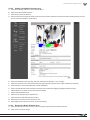
8.2. Camera Web Browser Interface
The web browser Home screen displays video and current information from the camera feed. The camera name, time signature,
video frame size and frames per second (FPS) being streamed are all displayed by default. Use the drop-down menus and buttons
to interact with the cameras inputs and outputs, change the stream, or enter the setup menus.
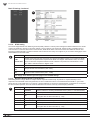
8.2.1. Web Interface Layout - Top Bar
(Buttons are enlarged for reference)
1. Video (Full Screen Mode)
Click to expand the view to full-screen mode. Press the Escape key or double-click the full-screen image to return to the
standard Live View screen.
2. Zoom (Digital Zoom Window)
Clicking Digital Zoom opens the Digital Zoom window. Use the slider to
magnify the camera view to a small area of the screen.
The Live View will only remain at this zoom level and area selection for the
current viewing session. When the user leaves Live View, the zoom level
resets to 100%.
3. Record
Record the current live stream to an .AVI video le that is saved to the PC or a network drive. A window opens for selecting
the storage location each time recording is started. Press Record again to stop the recording. The quality of this recording will
vary based on the bandwidth of the connection to the camera and the processing power of the local computer.
4. Photo
Takes a JPEG snapshot of the current image that can be saved to the PC or a network drive.
5. Cong
Click to enter the Conguration menus. All network and camera settings are congured in this menu. You must be logged in
with administrator privileges to access the Conguration Menu.
1 2 3 4 5

17
© 2014 Wirepath Surveillance
WPS-550-DOM-IP Installation Manual
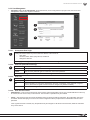
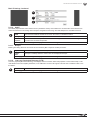
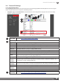
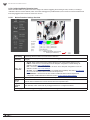
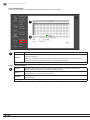
8.2.2. Web Interface Layout - Bottom Bar
1. Information Bar
Displays basic information about the camera feed.
2. Video Size
Adjusts the size of the Live View area within the browser window.
3. Video Source (If Streaming 2 is enabled)
Allows for selection of one of two video streams from the camera. Typically, Streaming 1 is congured for a high resolution
stream for viewing over a faster connection, and Streaming 2 is to a lower resolution for viewing over slower connections. See
section 9.4.3. Video Settings Menu Overview for information about streaming features and setup.
4. Online Visitors
Displays the number of users (all permission levels) currently logged in to view the camera. If anonymous viewing is allowed,
all anonymous viewers will also be counted. If you are the only user, then the number will be 1, unless an NVR is attached,
which will add 2 users to the count.
1 2 3 4

18
WPS-550-DOM-IP Installation Manual
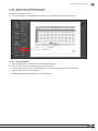
9. Camera Conguration Menu Setup
After browser access to the camera has been established, the remaining steps for setup may be completed so that cameras are
remotely viewable (from inside and outside of the LAN) but secure from unwanted access.
9.1. Conguration Menu - Access and Navigation
9.1.1. Accessing the Menu
To change settings in the cameras, click the “Cong” button in the top right corner of the Live View Screen.
Important! If you click “Cong” while logged in under a guest account (any account except the root “admin”
account) you will be prompted for a log in. You must enter the “admin” credentials to access the menu.
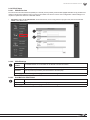
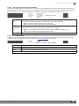
9.1.2. Conguration Menu Layout
The the left column of the Conguration menu screen contains the navigation links for all Conguration sub-menus. The rst sub-
menu, System Information, appears by default:
9.1.3. Conguration Menu Guidelines
• When changing settings, some values will be saved automatically. Others require that an “Apply” button be clicked to save the
change. Navigating away from pages with an “Apply” button without saving will cause settings to revert. Be sure to scroll down
to the bottom of any menu before navigating away to check for an option to apply the setting, or refer to the manual.

19
© 2014 Wirepath Surveillance
WPS-550-DOM-IP Installation Manual
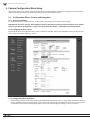
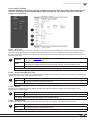
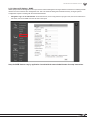
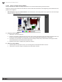
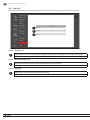
9.2. System Information and Settings
9.2.1. System Information Menu Settings
• Navigation: Log in as an administrator. From Home Screen, click “Cong” button in top right corner.
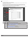
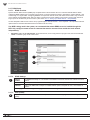
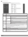
9.2.1.1. Server Information
1
MAC Address Cannot be changed. Use the MAC address to identify a camera if IP settings have been lost.
Server Name Modify the name given to the camera during IP Installer Setup. (Limited to 31 characters)
Language Select the desired language for camera software text.
Status Bar (Check box option to right of Server Name eld) Check to display the status bar in the camera image.
Click “Apply” at the bottom-right of the page to save modied settings.
9.2.1.2. OSD Setting
2
Time Stamp Select whether the camera’s time and date information are recorded and transmitted with video.
Position (If Time Stamp is enabled) Select where the OSD stamp text and system information appears.
OSD_Display Click the Text Edit button to enter OSD_Display Text Editor:
Text Enter text to be displayed beside the System Time and Date.
Size Set the point size of the OSD text using the drop-down.
Transparency Set the transparency of the OSD text to be more or less visible.
Click “Apply” at the bottom-right of the page to save modied settings.
1
2
3
4

20
WPS-550-DOM-IP Installation Manual
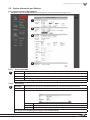
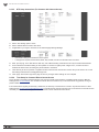
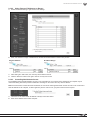
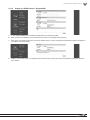
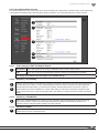
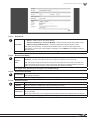
9.2.1.3. Time Setting
3
Server Time Current time based on the settings saved in the camera.
Date Format Select the order in which days (d), months (m), and years (y) are displayed.
Time Zone
(Only available for NTP and Manual mode) Set the camera time zone in hours ahead of or behind
Greenwich Mean Time (GMT).
Enable
Daylight
Savings Time
Check to enable Daylight Savings Time Settings. When this setting is enabled, DST start and end times
may be set. Default times are standard for most participating regions.
Time setup options are detailed in section 9.2.2. Camera Time Setup.
Click “Apply” at the bottom-right of the page to save modied settings.
9.2.1.4. Network LED
4
Enable or disable the network status lights on the RJ45 connector (back of the camera) The LEDs are useful for setup
and diagnostics, but may cause unwanted color reections behind the camera during regular use.
3
4
Page is loading ...
Page is loading ...
Page is loading ...
Page is loading ...
Page is loading ...
Page is loading ...
Page is loading ...
Page is loading ...
Page is loading ...
Page is loading ...
Page is loading ...
Page is loading ...
Page is loading ...
Page is loading ...
Page is loading ...
Page is loading ...
Page is loading ...
Page is loading ...
Page is loading ...
Page is loading ...
Page is loading ...
Page is loading ...
Page is loading ...
Page is loading ...
Page is loading ...
Page is loading ...
Page is loading ...
Page is loading ...
Page is loading ...
Page is loading ...
Page is loading ...
Page is loading ...
Page is loading ...
Page is loading ...
Page is loading ...
Page is loading ...
Page is loading ...
Page is loading ...
Page is loading ...
Page is loading ...
Page is loading ...
Page is loading ...
Page is loading ...
-
 1
1
-
 2
2
-
 3
3
-
 4
4
-
 5
5
-
 6
6
-
 7
7
-
 8
8
-
 9
9
-
 10
10
-
 11
11
-
 12
12
-
 13
13
-
 14
14
-
 15
15
-
 16
16
-
 17
17
-
 18
18
-
 19
19
-
 20
20
-
 21
21
-
 22
22
-
 23
23
-
 24
24
-
 25
25
-
 26
26
-
 27
27
-
 28
28
-
 29
29
-
 30
30
-
 31
31
-
 32
32
-
 33
33
-
 34
34
-
 35
35
-
 36
36
-
 37
37
-
 38
38
-
 39
39
-
 40
40
-
 41
41
-
 42
42
-
 43
43
-
 44
44
-
 45
45
-
 46
46
-
 47
47
-
 48
48
-
 49
49
-
 50
50
-
 51
51
-
 52
52
-
 53
53
-
 54
54
-
 55
55
-
 56
56
-
 57
57
-
 58
58
-
 59
59
-
 60
60
-
 61
61
-
 62
62
-
 63
63


Wirepath WPS-550-DOM-IP-BL Owner's manual
- Category
- Security cameras
- Type
- Owner's manual
- This manual is also suitable for
Ask a question and I''ll find the answer in the document
Finding information in a document is now easier with AI
Related papers
-
Wirepath WPS-300-DOM-IP-BL Owner's manual
-
-
Wirepath WPS-750-DOM-IP Owner's manual
-
-
-
-
-
-
-
Wirepath WPS-550-DOM-IP-BL Quick start guide
Other documents
-
Asoni CAM641 User manual
-
Security Camera King IPOD-SB8IR28A-B User manual
-
 Zxtech Stratox User manual
-
-
-
-
Hunt Electronic HLC-85ED User manual
-
Poewit WP-4 User guide
-
 LizaTech LIZUSBPLUG32GB Installation guide
-
AVer SF2012H-C User manual

