Page is loading ...

Telegesis™ TG-PM-0518-ETRX357USB r4
ETRX3USB Product Manual
©
2015 Silicon Labs ETRX3USB Product Manual (r4)
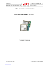
ZigBee
®
USB STICKS:
ETRX3USB
ETRX3USB-LRS
ETRX3USB+8M
ETRX3USB-LRS+8M
P
RODUCT MANUAL
Telegesis™ is a trademark of Silicon Laboratories Inc.

ETRX3USB
©2015 Silicon Labs - 2 - ETRX3USB Product Manual (r4)
Table of Contents
1 INTRODUCTION ................................................................................................................. 3
1.1 Supported Operating Systems ......................................................................................... 3
2 ABSOLUTE MAXIMUM RATINGS ..................................................................................... 4
3 8MB FLASH MEMORY ....................................................................................................... 4
3.1 Connections ..................................................................................................................... 4
3.2 Firmware .......................................................................................................................... 5
4 OPERATING CONDITIONS ................................................................................................ 6
5 REGULATORY INFORMATION ......................................................................................... 7
5.1 FCC compliance Class B Digital Device ........................................................................... 7
5.2 Canada – Industry Canada (IC) ........................................................................................ 7
5.3 European Certification ...................................................................................................... 7
5.4 General ............................................................................................................................ 8
6 ETRX357 I/O CONNECTIVITY ............................................................................................ 8
7 FIRMWARE UPGRADES ................................................................................................... 8
8 DRIVER INSTALLATION AND OPERATION ..................................................................... 9
8.1 Windows XP/Vista/7 Driver Installation ............................................................................. 9
8.2 Macintosh and Linux drivers ........................................................................................... 11
9 CUSTOM FIRMWARE DEVELOPMENT .......................................................................... 11
10 ORDERING INFORMATION ............................................................................................. 13

ETRX3USB
©2015 Silicon Labs - 3 - ETRX3USB Product Manual (r4)
1 Introduction
The ETRX3USB ZigBee USB Stick is effectively an RS232 to USB bridge connected to an ETRX3
Series ZigBee module. This allows connectivity to a computer’s USB port.
The ETRX3USB+8M and ETRX3USB-LRS+8M include an 8Mbit flash memory chip which can be
accessed by the firmware in the EM357 ZigBee chip inside the USB stick.
The ETRX3USB-LRS and ETRX3USB-LRS+8M have an ETRX357-LRS module in place of the
ETRX357 for longer range. The LRS variant has higher output power and better receiver sensitivity;
consult the ETRX357 and ETRX357-LRS Product Manuals for the full details.
The supplied Windows drivers create a virtual COM Port, so that the command line of the ETRX3
series module can be accessed via any terminal software application.
When using Windows
®
the Telegesis Terminal application can be used as described in the ETRX357
Development Kit manual.
1.1 Supported Operating Systems
Windows 98SE
Windows XP/Vista/7
Windows 2000
Windows CE *
MAC OS-9
MAC OS-X *
Linux *
* drivers for these systems are available from Silicon Labs though most Linux distributions now
include a suitable driver. The bridge chip is a CP2102 with Vendor ID 0x10C4 and Product ID
0x8293.

ETRX3USB
©2015 Silicon Labs - 4 - ETRX3USB Product Manual (r4)
2 Absolute Maximum Ratings
Parameter
Min.
Max.
Units
Condition
Supply Voltage Vdd
-0.3
5.5
V
Voltage on any pin
-0.3
V
dd
+0.3, max 5.8
V
Storage Temperature range
-40
150
°C
Table 1: Absolute Maximum Ratings
The absolute maximum ratings given above should under no circumstances be violated. Exceeding
one or more of the limiting values may cause permanent damage to the device.
3 8Mb flash memory
3.1 Connections
The +8M devices in the USB stick family contain a Winbond W25Q80DV 8Mb serial flash memory
chip with SPI interface to the EM357. The pin connections to the EM357 are shown in Figure 1.
Figure 1. Flash memory connections to EM357
At the time of writing the datasheet for the Winbond W25Q80DV flash memory chip is available at:
www.winbond.com/hq/product/code-storage-flash-memory/serial-nor-
flash/?__locale=en&partNo=W25Q80DV
/CS
DO
/WP
GND
VCC
/HOLD
CLK
DI
PA0
PA3
PA2
PA1
VCC
VCC
W25Q80DV
VCC
GND

ETRX3USB
©2015 Silicon Labs - 5 - ETRX3USB Product Manual (r4)
3.2 Firmware
The Telegesis R3xx firmware does not have any capability of driving the SPI connection to the
memory chip. Users will have to write or commission custom firmware to make use of this external
memory.

ETRX3USB
©2015 Silicon Labs - 6 - ETRX3USB Product Manual (r4)
4 Operating Conditions
Typical values at 5V 25°C.
Parameter
Min.
Typ.
Max.
Units
Condition
Supply Voltage, Vdd
4.5
5
5.5
V
Supply Current
ETRX3USB
56
1
mA
TX 8dBm
54
2
mA
TX 3dBm
54
1
mA
TX –43dBm
52.5
1
mA
RX
29.5
1,3
mA
SED, Power Mode 01
27
1,2
mA
SED, Power Mode 02
26
1,2
mA
SED, Power Mode 03
Operating ambient
temperature range
-20
25
85
°C
Table 2: Operating Conditions
The Winbond memory chip in the 8M variants draws extra current as shown in Table 3. Full details
of its power consumption can be found in the Winbond W25Q80DV datasheet.
Operation
Current
Units
Typ
Max
Standby
10
50
µA
Read 50MHz
7
15
mA
Write Status Register
20
25
mA
Page Program
20
25
mA
Sector/Block Erase
20
25
mA
Chip Erase
20
25
mA
Table 3: Flash memory current consumption
1
During USB suspend the current will drop by 25.6mA in all modes.
2
During USB suspend the current will drop by 25.6mA in all modes.
3
Please note that the power consumption in various power modes is firmware and usage dependent.

ETRX3USB
©2015 Silicon Labs - 7 - ETRX3USB Product Manual (r4)
5 Regulatory Information
The ETRX3USB and ETRX3USB+8M as well as the ETRX3USB-LRS and ETRX3USB-LRS+8M
have been designed to meet all national regulations for world-wide use. In particular the following
certifications have been obtained:
5.1 FCC compliance Class B Digital Device
This device complies with part 15 of the FCC Rules. Operation is subject to the following two
conditions:
1. This device may not cause harmful interference, and
2. This device must accept any interference received, including interference that may cause
undesired operation.
Note: This equipment has been tested and found to comply with the limits for a Class B digital device,
pursuant to part 15 of the FCC Rules. These limits are designed to provide reasonable protection
against harmful interference in a residential installation. This equipment generates, uses and can
radiate radio frequency energy and, if not installed and used in accordance with the instructions,
may cause harmful interference to radio communications. However, there is no guarantee that
interference will not occur in a particular installation. If this equipment does cause harmful
interference to radio or television reception, which can be determined by turning the equipment off
and on, the user is encouraged to try to correct the interference by one or more of the following
measures:
• Reorient or relocate the receiving antenna.
• Increase the separation between the equipment and receiver.
• Connect the equipment into an outlet on a circuit different from that to which the receiver is
connected.
• Consult the dealer or an experienced radio/TV technician for help.
Modifications not expressly approved by the manufacturer could void the user's authority to operate
the equipment under FCC rules. An FCC declaration of conformity is available separately from the
Telegesis website
The ETRX3USB and ETRX3USB+8M contain a modular radio transmitter with FCC ID
S4GEM35XA. The ETRX3USB-LRS and ETRX3USB-LRS+8M contain a modular radio transmitter
with FCC ID S4GEM35XB.
5.2 Canada – Industry Canada (IC)
This Class B digital device complies with Canadian ICES-003. Cet appareil numérique de la classe B
est conforme à la norme NMB-003 du Canada.
5.3 European Certification
The ETRX3USB and ETRX3USB+8M as well as the ETRX3USB+LRS and ETRX3USB-LRS+8M
limited to a maximum power level of 21.15mW e.i.r.p. (13.2dBm) have been tested and comply with
the following standards:
Radio: EN300 328 v1.8.1

ETRX3USB
©2015 Silicon Labs - 8 - ETRX3USB Product Manual (r4)
EMC: EN301 489-17 v2.2.1
Safety: EN60950-1:2006/A12:2011
An EC declaration of conformity is available separately from the Telegesis website.
Important Note: In Europe the regulations for the 2.4GHz frequency band only permit.a maximum
power spectral density of 10mW/MHz, which with a ZigBee spectrum equates to an e.i.r.p of 13dBm.
The ETRX3USB cannot reach this level but the ETRX3USB-LRS can exceed it, so in the latter device
the power out of the EM357 chip into the RF power amplifier should be limited to -11dBm. Refer to
the ETRX357-LRS Product Manual for more details.
5.4 General
For further technical information, including radio certification, see the corresponding ETRX3 series
Module Product Manuals.
When ordering ETRX3USB sticks without printed branding on the case, you may be responsible for
applying a marking appropriate to their geographical area of use, such as the CE marking.
For more information on ZigBee compliance and the AT command interface firmware please refer
to the latest AT command dictionary and the ETRX357 user guide.
6 ETRX357 I/O Connectivity
The I/Os of the built-in ETRX357 are connected as follows:
PA6 is connected to the LED (drive PA6 low to sink LED current).
PB3 is the CTS input for the ETRX357. Make sure PB3 is never defined as an output.
PB4 is the RTS input for the ETRX357.
Important Note: The lines for hardware handshaking are connected, so even when not using
hardware handshaking PB3 should never be defined as an output as this would drive against the
incoming CTS signal via a 1kΩ resistor and increase the current consumption.
7 Firmware upgrades
The firmware which is loaded onto the embedded ETRX357 Module can be upgraded over the air
or via the virtual COM port as described in the ETRX357 Development Kit Product Manual.
Alternatively, access to the SIF programming interface is possible by opening the cover on the side
of the ETRX3USB ZigBee USB stick.

ETRX3USB
©2015 Silicon Labs - 9 - ETRX3USB Product Manual (r4)
8 Driver Installation and Operation
The drivers provided will generate a virtual COM port allowing easy access to the serial port of the
embedded ETRX357.
To read more about the ETRX357 wireless mesh networking module and its command line interface
please read the corresponding documentation which can be found
at http://www.silabs.com/telegesisdocuments
.
8.1 Windows XP/Vista/7 Driver Installation
The driver package downloadable from the Support
Software centre page
at http://www.silabs.com/telegesissoftware
should be unzipped into a local folder. When executing
the file ‘TgVCPInstaller.exe’ prior to plugging in the ETRX3USB stick an installer will guide you
through the steps required for the driver installation.
Figure 2: Found New Hardware Wizard
After insertion of the stick, Windows
®
may prompt that new hardware has been found. If you have
run the ‘TgVCPInstaller.exe’ Windows will be able to install the driver by automatically, but if you
have not run ‘TgVCPInstaller.exe’ you will have to manually point to the directory into which you
have unzipped the driver.
Please note that each ETRX3USB has a unique serial number which requires the installation
procedure to be repeated with every new ETRX3USB being attached to the computer, though the
process is not obtrusive. This allows multiple ETRX3USB sticks to be used on the same computer
at any one time.

ETRX3USB
©2015 Silicon Labs - 10 - ETRX3USB Product Manual (r4)
In order to find out the identity/number of the virtual COM port the stick has been assigned to, please
open the Device Manager under the Windows Computer Management screen (see below) and click
on the Ports (COM and LPT) section where you should find the new virtual COM port. By double
clicking on the entry of the virtual COM port you can also change the number assigned to the virtual
COM port when entering the advanced setup of the device.
Figure 3. Device Manager
Once the correct COM port has been selected, the Terminal software can be used to control the
ETRX3USB stick as per the Development Kit Manual. Telegesis Terminal is a free download
from http://www.silabs.com/telegesissupport

ETRX3USB
©2015 Silicon Labs - 11 - ETRX3USB Product Manual (r4)
Figure 4. Telegesis Terminal
8.2 Macintosh and Linux drivers
A Virtual Com Port driver kit for Mac and Linux can be obtained by following the link on our website
on the Support
Software centre page. Recent versions of the Linux kernel have native support
for Telegesis USB devices.
The Silicon Laboratories CP2102 serial-to-USB bridge chip is configured with Vendor ID 0x10C4
and Product ID 0x8293, and the drivers must be written to recognise these identifiers.
9 Custom Firmware Development
If you intend to develop custom firmware to go onto the ETRX3USB you need to contact Silicon Labs
to obtain access to their suite of development tools and their stack. The USB stick contains an
ETRX357 module based on the Silicon Labs EM357 and a USB-to-serial bridge chip. The ETRX357
communicates via its serial port, so the user’s firmware must use the UART of Serial Controller 1.
The nRTS and nCTS lines are connected to the USB bridge chip. The LED on the USB stick is
driven from EM357 pad PA6.
In order to download custom firmware onto the ETRX357, the Silicon Labs bootloader can be used
or alternatively the ETRX3USB can be directly connected to the Silicon Labs InSight Adapter for
programming and real time debugging.

ETRX3USB
©2015 Silicon Labs - 12 - ETRX3USB Product Manual (r4)

ETRX3USB
©2015 Silicon Labs - 13 - ETRX3USB Product Manual (r4)
10 Ordering Information
Table 11. Ordering Information (see Telegesis website for more products)\
Ordering/Product Code
Description
ETRX3USB
USB stick with ETRX357 module
ETRX3USB-LRS
USB stick with ETRX357-LRS long-range module
ETRX3USB+8M
USB stick with ETRX357 module and 8Mb flash memory chip
ETRX3USB-LRS+8M
USB stick with ETRX357-LRS long-range module and 8Mbit
flash memory chip
ETRX357
Telegesis Wireless Mesh Networking Module with Silicon Labs
ZigBee Technology:
• Based on Silicon Labs EM357
• Telegesis AT Style Command Interpreter based on
EmberZNet meshing and self-healing ZigBee PRO stack
• Integrated 2.4GHz Antenna
ETRX357HR
Telegesis Wireless Mesh Networking Module with Silicon Labs
ZigBee
Technology:
• Based on Silicon Labs EM357
• Telegesis AT Style Command Interpreter based on
EmberZNet meshing and self-healing ZigBee PRO stack
• U.FL coaxial Antenna Connector
ETRX357DVK
Telegesis Development Kit with:
• 3 x ETRX35xDV Development Boards
• 3 x USB cables
• 2 x ETRX35x on carrier boards
• 2 x ETRX35xHR on carrier boards
• 2 x ETRX35x-LRS on carrier boards
• 2 x ETRX35xHR-LRS on carrier boards
• 1 x ETRX3USB USB stick
• 2 x ½-wave antennae
•
2 x ¼-wave antennae
Notes:
• Customers’ PO’s must state the Ordering/Product Code.
• There is no
“blank” version of the ETRX357 Module available. All Modules carry both the
Silicon Labs
Stack and the Telegesis AT style Command Layer. Where customers wish
to add their own firmware they can erase and write it to the flash memory of the EM357.
• Please
contact Telegesis if you require additional AT style commands or specific
integration assistance.

http://www.silabs.com
Silicon Laboratories Inc.
400 West Cesar Chavez
Austin, TX 78701
USA
Smart.
Connected.
Energy-Friendly.
Products
www.silabs.com/products
Quality
www.silabs.com/quality
Support and Community
community.silabs.com
Disclaimer
Silicon Laboratories intends to provide customers with the latest, accurate, and in-depth documentation of all peripherals and modules available for system and software implementers using
or intending to use the Silicon Laboratories products. Characterization data, available modules and peripherals, memory sizes and memory addresses refer to each specific device, and
"Typical" parameters provided can and do vary in different applications. Application examples described herein are for illustrative purposes only. Silicon Laboratories reserves the right to
make changes without further notice and limitation to product information, specifications, and descriptions herein, and does not give warranties as to the accuracy or completeness of the
included information. Silicon Laboratories shall have no liability for the consequences of use of the information supplied herein. This document does not imply or express copyright licenses
granted hereunder to design or fabricate any integrated circuits. The products are not designed or authorized to be used within any Life Support System without the specific written consent
of Silicon Laboratories. A "Life Support System" is any product or system intended to support or sustain life and/or health, which, if it fails, can be reasonably expected to result in significant
personal injury or death. Silicon Laboratories products are not designed or authorized for military applications. Silicon Laboratories products shall under no circumstances be used in
weapons of mass destruction including (but not limited to) nuclear, biological or chemical weapons, or missiles capable of delivering such weapons.
Trademark Information
Silicon Laboratories Inc.® , Silicon Laboratories®, Silicon Labs®, SiLabs® and the Silicon Labs logo®, Bluegiga®, Bluegiga Logo®, Clockbuilder®, CMEMS®, DSPLL®, EFM®, EFM32®,
EFR, Ember®, Energy Micro, Energy Micro logo and combinations thereof, "the world’s most energy friendly microcontrollers", Ember®, EZLink®, EZRadio®, EZRadioPRO®, Gecko®,
ISOmodem®, Precision32®, ProSLIC®, Simplicity Studio®, SiPHY®, Telegesis, the Telegesis Logo®, USBXpress® and others are trademarks or registered trademarks of Silicon Laborato-
ries Inc. ARM, CORTEX, Cortex-M3 and THUMB are trademarks or registered trademarks of ARM Holdings. Keil is a registered trademark of ARM Limited. All other products or brand
names mentioned herein are trademarks of their respective holders.
/