Page is loading ...

1
1031012 Rev.A 09/05
LO
CK
UN
LO
CK
ST
AR
T
!
PART NUMBER (s):
0000-8F-L10
APPLICABLE MODELS:
2004>MAZDA3
All Models With
Power Door Locks
REMOTE START SYSTEM
WITH VEHICLE SECURITY
AND KEYLESS ENTRY
KIT CONTENTS
Remote Start DNA Card Remote Start Dipole Antenna Remote Start
Control Module (QTY-1) Transmitters (QTY-1) Wire Harness
(QTY-1) (QTY-2) (QTY-1)
P/N: 0000-8F-Z01 P/N: 0000-8F-L16 P/N: 0000-8F-F06 P/N: 0000-8F-Z10 P/N: 0000-8F-L02
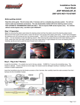
1. Disconnect negative battery terminal:
a. Remove relay cover by grasping rear of cover and pulling upwards.
Disengage locking tabs and remove cover. (FIGURE A)
b. Disengage locking tabs and remove cover the battery cover.
c. Disconnect negative battery terminal and isolate.
GENUINE ACCESSORIES
INSTALLATION INSTRUCTIONS
®
Owner's Manual
Vehicle Remote Start System
TM
Featuring PowerCode Technology
For the Ultimate in Comfort, Convenience and Security
TM
MAZDA
GENUINE ACCESSORIES
WARNING: / AVERTISSEMENT
This vehicle is equipped with a remote controlled engine starter.
To reduce the risk of serious Injury or death, switch engine starter
system into service mode and disconnect the vehicle battery
before performing any service on the vehicle.
Ce véhicule est doté d'un démarreur à distance. Pour réduire les
risques de blessures graves ou mortelles, mettre le démarreur à
distance en mode service et débrancher la batterie du véhicule
avant d'effectuer des travaux d'entretien sur celui-ci.
30
sec.
2 sec.
5X
2 sec.
Immobilizer Interface Adhesive Primer 2- Sided Tape
Module and Harness (QTY-1) (QTY-1)
(QTY-1)
Tie Wrap
(QTY 2)
IDC Wire Tap
(QTY 2)
Hood Safety
Switch
(QTY 1)
Owners
Manual
(QTY 1)
Wallet
Card
(QTY 1)
Underhood
Sticker
(QTY 1)
Long Tie
Wrap
(QTY 3)
Mini Fuses
(QTY - (1) 5 AMP)
(QTY - (7) 15 AMP)
1/4” Self
Drilling Screws
(QTY 2)
PARTS BAG CONTENTS
HOOD SAFETY SWITCH KIT CONTENTS
(P/N: 0000-8F-H03)
Locking
Washer
(QTY 2)
TOOLS REQUIRED
SAFETY GLASSES
ELECTRICAL TAPE
WIRE CUTTERS
PLIERS
ALCOHOL or GLASS CLEANER
PHILLIPS SCREWDRIVER
POWER DRILL
9/32” DRILL BIT
FIBER STICK
10mm SOCKET AND RATCHET
1/4” SOCKET AND DRIVE
3/8” DRIVE TORQUE WRENCH
3/8” DRIVE 10mm SOCKET
0
IMMOBILIZER INTERFACE KIT CONTENTS
(P/N: 0000-8F-H05)
FIGURE A
1
VEHICLE PREPARATION
NOTE: BOTH PROGRAMMED
IGNITION KEYS ARE REQUIRED
AT TIME OF INSTALLATION
PRE INSTALLATION
1. CLEAN HANDS
2. OPEN DRIVER’S DOOR WINDOW
3. RECORD RADIO STATIONS
4. SET PARKING BRAKE
5. DISCONNECT AND ISOLATE
NEGATIVE BATTERY TERMINAL
6. VEHICLE MUST BE AT ROOM
TEMPERATURE
Tie Wrap LED IDC Wire Tap
(QTY-10) (QTY-1) (QTY-7)
& L10A
0000-8F-D19
(QTY 1 / 0000-8F-Z12)

2
1031012 Rev.A 09/05
VEHICLE PREPARATION, continued
2. Remove the following components:
a. Using a fiber stick remove the driver’s side scuff plate.
b. Remove the driver’s side kick panel by using a fiber stick
pull the plastic center button of the plastic fastener out to dis-
engage (FIGURE B). Gently pull the kick panel towards the
rear of the vehicle to remove.
c. Unclip the hood release by inserting a fiber stick between the
hood release and the dash panel. There is a center tab the
stick must push down while pulling the hood release towards
the rear of the vehicle.
d. Remove one (1) phillips screw behind the hood release handle.
(FIGURE C)
e. Carefully pull the rubber weather seal away from the door jamb
along the lower dashboard panel. Unclip the lower dash panel
using a fiber stick starting at the bottom and unplug any con-
nectors attached to the panel.
f. Remove the three (3) phillips head screws from the lower steer-
ing column shroud, and remove the shroud. (FIGURE D and
E)
g. Remove the lower center console kick panels from both driver
and passenger sides by using a fiber stick to pull the plastic
center button of the plastic fastener out to disengage (FIG-
URE F). Gently pull the kick panel towards the rear of the
vehicle to remove.
h. Remove the driver’s side A-pillar panel being careful not to
damage the retaining clips or the curtain airbag. Carefully pull
the rubber weather seal away from the door jamb (FIGURE
G) then, starting at the top of the panel, pull the A-pillar panel
toward the inside of the car but DO NOT try to pull all the way
off. There is a white clip at the top which only releases about
an inch then the panel must be slid off of it by pulling upward.
Be very careful not to damage the head liner or break the
white top clip.
i. Push the white top clip back into the A-pillar half way until it
rotates freely.
j. turn the white top clip diagonally and pull straight out of the A-
pillar. (FIGURE H)
k. Slide the removed white clip into position on the A-pillar panel.
(FIGURE I)
1
FIGURE B
FIGURE D
FIGURE E
FIGURE F
FIGURE H
FIGURE C
FIGURE G
FIGURE I

3
1031012 Rev.A 09/05
DIPOLE ANTENNA MOUNTING
1. Clean mounting spot with an alcohol pad prior to mounting. Mount
the dipole antenna to the windshield 210mm to the right of center on
the windshield, directly below the black windshield trim material. (FIG-
URE J)
2. Run the antenna wire above the headliner to the driver’s A-pillar,
using a fiber stick to secure under the headliner.
Note: Make sure the antenna wire is secure under the head
liner, if necessary remove the sun visor to secure.
3. Route the antenna wire down the A-pillar securing it to the existing
wiring using (3) supplied tie wraps. Do not secure it directly to the
sunroof drain tube or airbag. (FIGURE K)
4. Route the antenna wire behind the left side of the dashboard. The
antenna will be connected to the remote start control module later.
5. Re-install the driver’s side A-pillar panel and re-install the weather
seal along the A-pillar.
2
FIGURE J
FIGURE K
HOOD SAFETY SWITCH MOUNTING
1. Using (2) supplied 1/4” self drilling screws and (2) supplied lock washers, secure the hood safety switch to
the drivers side of the vehicle’s hood 95mm below the drain hole and 60mm from the side edge. (FIGURE
L & M)
2. Route the hood safety switch wiring down into the engine compartment along the inside of the hood hinge
and secure using (2) supplied tie wraps. (FIGURE L & N)
3. Route the hood safety switch wiring along the cowl panel, tucking under the cowl panel where possible, into
the engine compartment towards the hood release cable grommet. (FIGURE L & O)
4. Disengage hood latch cable and pull through radiator support bracket.
CAUTION: Failure to secure hood latch open with a tie wrap could allow the hood to become
locked without the hood release cable available.
a. Attach a tie wrap to the hood latch mechanism. (FIGURE P)
b. Disconnect the hood latch cable at latch.
c. Free the hood latch cable from (2) retaining clips. (FIGURE Q)
3
FIGURE N
FIGURE M
FIGURE P
FIGURE Q
FIGURE O
FIGURE L

4
1031012 Rev.A 09/05
FIGURE S
HOOD SAFETY SWITCH MOUNTING CONTINUED
5. Locate the hood release cable grommet from inside the occupant compartment. (FIGURE R)
6. Pull the hood release cable and grommet approximately 20” into the driver’s side footwell.
(FIGURE S)
7. Using fish wire, pull the hood safety switch wiring through the hood release cable opening:
a. From inside of the vehicle, insert the fish wire through the hood release cable opening.
b. Bend approximately three (3) inches of harness at wire end.
c. Using electrical tape, secure fish wire to harness as shown. (FIGURE T)
d. Pull fish wire and wiring through hood release cable opening. (FIGURE L, page 3)
e. Tape the hood safety switch wires against the fish wire and electrical tape in place. (FIGURE U)
f. Slide the fish wire and wiring through the hood release grommet and pull the excess wiring
through the grommet. (FIGURE V)
8. Reconnect the hood release cable:
a. Pull the hood release cable back into position. Reattach to hood latch release mechanism and
two (2) retaining clips. (NOTE: Ensure the hood latch cable retaining collar is seated securely).
b. Remove the tie wrap from the hood latch release mechanism.
c. Slide the hood release cable grommet back into position in the vehicle dashwall.
3
FIGURE V
FIGURE R
FIGURE U
FIGURE T

5
1031012 Rev.A 09/05
REMOTE START CONTROL MODULE PREPARATION
1. Insert the supplied fuses into the remote start control module as shown in below (FIGURE W).
the fuses fit tight so use a tool handle to seat them in place if necessary.
2. Install DNA card into the remote start control module as shown below. (FIGURE X)
NOTE: Use care to assure that both rows of the multipin connectors are aligned and seated properly.
3. Plug the supplied wire harness 10-way, 24-way and 16-way connectors into the remote start control
module (FIGURE Y). Make sure the harnesses are seated completely. NOTE: The connectors will only
plug into the remote start control module one way.
4. Plug the supplied immobilizer interface 4-way connector into the remote start control module. (FIGURE
Y)
NOTE: TAPE OFF THE WHITE WIRE (IF EQUIPPED) COMING FROM THE 4-WAY CONNECTOR
(THIS WIRE IS NOT USED ON THIS SYSTEM).
4
FIGURE W
5
15
15
15
15
15
15
5
15
15
15
15
15
15
-+
-+
15
HVAC 1
HVAC 2
MAIN B+
IGNITION
DOME LIGHT
PK LIGHTS
DOOR LOCK
S
15
TRUNK RELEASE
To Immobilizer
Interface Module
FIGURE Y
FIGURE X
REMOTE ENGINE START MODULE AND IMMOBILIZER INTERFACE MOUNTING
5
Tie Wraps
REMOTE ENGINE START MODULE MOUNTING
1. Locate the large dashboard support bracket to the left of the steering
column.
2. Using a fiber stick to temporarily release the white harness fastener
to the left of the dashboard support brace to allow for easy place-
ment of the remote engine start control module. (FIGURE Z)
3. Using (2) supplied long tie wraps secure the remote start control
module to the left side of the dashboard support bracket. Make sure
that the remote start control module is not mounted to far down on
the bracket, this will eliminate problems with dashboard reassem-
bly. (FIGURE Z)
4. Route the dipole antenna cable (previously installed in step 2)
and plug into the 2-pin connector on the bottom of the remote
start control module.
IMMOBILIZER INTERFACE MODULE MOUNTING
1. Locate the Large dashboard support bracket to the right of the
steering column.
2. Using (1) supplied long tie wraps, secure the immobilizer interface to
the dashboard bracket. (FIGURE AA)
FIGURE Z
FIGURE AA

6
1031012 Rev.A 09/05
GROUND CONNECTION
1. Locate the 10mm factory ground lug located in the driver’s kick panel area.
(FIGURE BB)
2. Using a 10mm ratchet remove the 10mm lug bolt.
3. Re-secure the factory ground ringlet and remote start harness BLACK/
ORANGE ground wire with ringlet and tighten with a 10mm ratchet. (FIG-
URE CC)
NOTE: USING A 3/8” DRIVE TORQUE WRENCH MAKE SURE
THAT THE 10mm GROUND LUG BOLT IS SECURELY TIGHT-
EN 78-121 INCH/POUNDS.
7
FIGURE BB
HOOD SAFETY SWITCH MOUNTING WIRE CONNECTIONS
1. Locate the BLACK/ORANGE and GRAY/RED wire from the remote start system harness.
2. Locate the wires listed below. If the hood safety switch wire has a ground ringlet terminal or a stripped end
on either wire then cut the ends of the wires so they are blunt.
3. Using the (2) supplied IDC wire taps (in hood safety switch parts bag), connect the switch wires listed
below together and crimp the IDC wire tap in place using pliers, assure that a complete and secure
connection is made.
6
HOOD SAFETY SWITCH WIRE REMOTE START HARNESS WIRE
Dk. GRAY GRAY/RED
Dk. GRAY BLACK/ORANGE
NOTE: Switch is not polarity sensitive.
FIGURE CC

7
1031012 Rev.A 09/05
SYSTEM LAYOUT
PASSENGER'S SIDE UNDERDASH CONNECTIONS
LOCATED AT PASSENGER JUNCTION BOX (PJB)
PASSENGER'S SIDE UNDERDASH
NOT USED, TRIM AND TAPE OFF
BLACK-HORN OUTPUT CONNECTION LOCATED
AT PIN N OF THE J-04 CONNECTOR TOP OF PJB
BLACK/REC- TRUNK AJAR INPUT CONNECTION LOCATED
AT PIN X (5-DR) PIN Z (4-DR) J-06 CONNECTOR BOTTOM OF PJB
BLACK/WHITE- DOOR UNLOCK OUTPUT LOCATED
AT PIN AA J-06 CONNECTOR BOTTOM OF PJB
BLACK/BLUE- DOOR LOCK OUTPUT LOCATED
AT PIN Y J-06 CONNECTOR BOTTOM OF PJB
BLUE- DOOR AJAR INPUT/OUTPUT LOCATED
AT PIN U J-05 CONNECTOR BOTTOM OF PJB

8
1031012 Rev.A 09/05
WIRE HARNESS CONNECTIONS- STEERING COLUMN
8
IGNITION SWITCH CONNECTOR
1. Spot tape the immobilizer interface ribbon cable wiring to the ignition
harness making sure to leave enough slack to route over to the igni-
tion switch on the right side of the steering column.
2. Route the remote start ignition harness with 8-way male and fe-
male ignition connectors and 12-way male and female multifunction
switch connector, transponder interface wiring and ribbon cable
across and up the left of the steering column harness, do not secure
harness at this time.
3. Locate the 8-way WHITE and GREY ignition connector, on the left
side of the steering column.
4. Release the GREY secondary latch and remove the 8-way WHITE
ignition connector by pulling upwards.
5. Plug the remote start harness 8-way WHITE female connector into
the factory ignition switch, replace the GREY secondary latch and
secure harness in place. (FIGURE DD)
6. Connect the remote start harness 8-way male connector into the
factory ignition harness, and replace the GREY secondary latch.
(FIGURE EE)
MULTIFUNCTION SWITCH CONNECTOR
1. Locate the 12-way WHITE multifunction switch connector on the left
side of the steering column (plugged into the turn signal assembly).
2. Remove the 12-way connector from the multifunction switch.
3. Plug the 12-way female remote start harness connector into the
multifunction switch. (FIGURE FF)
4. Plug the previously removed vehicle 12-way female connector into
the remote start harness 12-way male connector. (FIGURE FF)
5. Using (2) supplied tie wraps, secure the 12 way multifunction switch
harness to the factory wiring on the left side of the steering column.
(FIGURE GG)
6. Using (2) supplied tie wraps secure the remote start wiring to the
vehicle’s factory ignition wiring. (FIGURE HH)
NOTE: IT IS EXTREMELY IMPORTANT THAT THE WIR-
ING IS SECURED IN A MANNER THAT WILL ALLOW THE
TILT/TELESCOPING STEERING WHEEL TO MOVE
FREELY AND STILL ALLOW FOR REASSEMBLY OF THE
STEERING COLUMN SHROUD. CHECK FUNCTIONAL-
ITY OF THE TILT TELESCOPING STEERING WHEEL
PRIOR TO REASSEMBLY.
FIGURE DD
FIGURE EE
FIGURE HH
FIGURE GG
FIGURE FF

9
1031012 Rev.A 09/05
IMMOBILIZER INTERFACE RIBBON CABLE MOUNTING
9
1. Route the immobilizer interface (previously installed) ribbon cable
to the ignition switch, making sure to keep it away from any moving
parts.
2. Following the instructions on the supplied ampule of adhesive primer,
apply a thin coating to the entire transceiver antenna ring (black plastic
ring around key switch, FIGURE II) and to the ribbon cable.
3. Remove the backing from one side of the supplied 2-way tape and apply
tape around the transceiver antenna ring (black plastic ring around key
switch, FIGURE JJ) keeping the tape off of the roundedpart of the igni-
tion switch face and trimming excess 2-way tape if necessary.
4. Remove the remaining backing on the 2-way tape and position the ribbon
cable around the transceiver antenna ring, with the striped side facing
the ignition key opening. (FIGURE KK)
5. Using a supplied tie wrap, secure the antenna coil. (FIGURE KK)
FIGURE KK
FIGURE II
FIGURE JJ

10
1031012 Rev.A 09/05
REMOTE START HARNESS VEHICLE WIRE
RED/WHITE-BRAKE SWITCH RED/WHITE
WIRE HARNESS CONNECTIONS- BRAKE SAFETY
1. Locate the brake switch connector mounted to the brake pedal assembly.
2. Temporarily unplug the connector from the brake switch and carefully remove 1”-2” inches of tape
covering the harness.
3. Place (1) supplied IDC wire tap on to the vehicle wire (using the side of the IDC wire tap that is
open on both ends).
4. Insert the wire from the remote start harness into the other side of the IDC wire tap and crimp in
place with pliers.
10
WIRE HARNESS CONNECTIONS- PASSENGER UNDERDASH
1. Route the passenger kick panel harness (with six (6) loose wires)
across the driver’s side lower dash using (1) supplied tie wrap,
secure the harness to the vehicle’s lower center console bracket.
(FIGURE LL)
NOTE: THE BLACK/GREEN WIRE WILL NOT BE CONNECTED,
TRIM AND TAPE OFF TO PREVENT SHORTING
2. Route behind the center console across transmission hump
to the passenger’s side lower dash.
3. Locate the vehicle’s Passenger Junction Box (PJB) and re-
move the small plastic cover. (FIGURE MM)
4. Release the (2) twist tabs that secure the PJB and lower the
PJB to the passenger’s side footwell. (FIGURE NN)
11
FIGURE NN
FIGURE LL
FIGURE MM
R/W RB R/Y
Brake Switch Connector
View From Harness Side

11
1031012 Rev.A 09/05
WIRE HARNESS CONNECTIONS- PASSENGER UNDERDASH, continued
SMALLER BROWN (J-06) CONNECTOR-BOTTOM OF PJB
1. Locate the small brown (J-06) connector on the bottom side of the PJB.
(FIGURE PP)
2. Place (1) IDC wire tap on each of the vehicle wires listed below (using the
side of the IDC wire tap that is open on both ends).
3. Insert the wire from the remote start harness into the other side of the IDC
wire tap and crimp in place with pliers.
11
REMOTE START HARNESS VEHICLE WIRE
BLACK/BLUE-DOOR LOCK OUTPUT BLACK/BLUE - Pin Y
BLACK/WHITE-DOOR UNLOCK OUTPUT BLACK/WHITE - Pin AA
BLACK/RED-TRUNK/HATCH PIN SWITCH BLACK/RED - Pin X (5DR) or Pin Z (4DR)
LARGER BROWN (J-05) CONNECTOR-BOTTOM OF PJB
1. Locate the small brown (J-05) connector on the bottom side of the SJB.
(FIGURE QQ)
2. Place (1) IDC wire tap on each of the vehicle wires listed below (using the
side of the IDC wire tap that is open on both ends).
3. Insert the wire from the remote start harness into the other side of the IDC
wire tap and crimp in place with pliers.
REMOTE START HARNESS VEHICLE WIRE
BLUE-DOME LIGHT INPUT/OUTPUT BLACK/BLUE - Pin U
FIGURE QQ
REMOTE START HARNESS VEHICLE WIRE
BLACK- HORN OUTPUT BLACK - Pin N
FIGURE OO
RE-MOUNT PJB
1. After all connections have been made, re-mount the PJB and secure with the twist tabs.
2. Re-install the PJB cover.
BLUE (J-04) CONNECTOR-TOP OF PJB
1. Locate the blue (J-04) connector on the top side of the PJB.
(FIGURE OO)
2. Place one (1) IDC wire tap on each of the vehicle wires listed below
(using the side of the IDC wire tap that is open on both ends).
3. Insert the wire from the remote start harness into the other side of
the IDC wire tap and crimp in place with pliers.
FIGURE PP
L/WGY/V
B/R
W
[W/R]
B/GB/LB/Y
B/W
B/LW/G
{B/P}
@W/G
B/LG
B/OB/O
AF
WAE Y
ZAB
AAAC
AD X
U
V
S
T
Q
R
O
P
M
N
K
L
I
J
G
H
E
F
C
D
A
B
<B>
B
#B/R
PJB J-04 Connector View From Harness Side
B/G
@B/R
B/O
[W/G]
B/Y
B/R
B/L
B/G
B/O B/G
# #B/W
AF
WAE Y
ZAB
AAAC
AD X
U
V
S
T
Q
R
O
P
M
N
K
L
I
J
G
H
E
F
C
D
A
B
B/L
B/LB/W
PJB J-06 Connector View From Harness Side
O
[BR/G]
G
P
W/BY/B
AK
L/R
AR
@W/R
AT
AG
AC AA V T R
C
LO/W
AL I
O
M
R/Y
QSU
B/L
ZAB
AF
G/B
A
AM BJ
@O/L
HD
K
AS
O/Y
AQ
E
AJ
[B/G]
L
F
#G/O
O/L
<O/B>
G/Y
<P/B>
[G/B]
W
YAE
ADAH
AI
AO
AP
AN
X
N
W/B
G/B
G/Y
{G/B}
G/L
G/L
PJB J-05 Connector View From Harness Side

12
1031012 Rev.A 09/05
LED MOUNTING
1. Locate a blank knockout switch panel on the lower dashboard panel.
2. Drill a 9/32” hole in the knockout switch panel, making sure the hole is centered approximately 10mm
from side edge and 5mm from top. (FIGURE RR)
4. Snap the supplied LED in the hole.
5. Route the 2-way LED connector from the remote start harness and plug into the LED connector.
6. Plug in any connectors to the driver’s side lower dashboard panel, re-mount the dashboard panel and re-
mount the rubber weather seal.
EMERGENCY OVERRIDE/PROGRAMMING BUTTON MOUNTING
1. Locate the previously removed driver’s side kick panel cover.
2. Drill a 9/32” hole at the top of the panel, approximately 76mm down and 102mm from the far edge.
3. Route the emergency override/programming button from the remote start harness down to the kick
panel.
4. Mount the emergency override/programming button in the drilled hole from behind and screw the mounting
cap in place. (FIGURE SS)
NOTE: DISCARD THE LOCK WASHER FROM THE EMERGENCY OVERRIDE/PROGRAM-
MING BUTTON
5. Re-install driver’s side kick panel cover
12
13
FIGURE RR
FIGURE SS
76mm
102mm

13
1031012 Rev.A 09/05
RE-ASSEMBLY
2. Re-install the following components:
a. Re-install the lower center console kick panels on both
driver and passenger sides. Re-secure the plastic fas-
tener on both. (FIGURE TT)
b. Re-install the steering column shroud by first securing
the ignition key light in place and then snapping the (2)
halves of the steering column shroud together. Re-in-
stall the (3) phillips screws on the bottom of the steering
column shroud. (FIGURE UU & VV)
c. Carefully pull the weather seal away along the door jamb
along the driver’s side lower dashboard. Re-mount the
driver’s side lower dashboard panel plugging in any con-
nectors that were removed earlier. Secure the weather
seal in place.
d. Re-install (1) phillips screw on the lower left side of the
driver’s side dashboard panel (FIGURE WW) and re-se-
cure the hood release handle.
14
FIGURE UU
FIGURE VV
FIGURE TT
FIGURE WW
SYSTEM POWER-UP
1. Verify that all connections are secure as per installation instructions.
2. Turn the ignition key to the RUN position.
3. Reconnect the negative battery terminal.
4. Turn the ignition key to the OFF position.
5. VERY IMPORTANT - USING THE IGNITION KEY, TURN THE IGNITION TO THE ON POSITION THEN
CRANK ENGINE UNTIL IT STARTS ONE TIME THEN SHUT THE VEHICLE OFF.
15
UNDERHOOD WARNING LABEL MOUNTING
16
1. Open the engine hood and find a suitable mounting location in the engine compartment that will
be in plain sight when the hood is open (on the radiator cowl).
2. Using an alcohol pad, clean the mounting surface thoroughly.
3. Remove the backing on the underhood sticker and mount in place.
4. Close hood.

14
1031012 Rev.A 09/05
IMMOBILIZER INTERFACE PROGRAMMING
NOTE: IF YOU DID NOT START THE CAR WITH THE IGNITION KEY AS INSTRUCTED TO IN SECTION 15 STEP 5
THEN THE VEHICLE WILL NOT ATTEMPT TO START, INSTEAD YOU WILL GET THREE ADDITIONAL BEEPS FROM
THE HORN. THE VEHICLE HAS TO BE STARTED AT LEAST ONCE WITH THE KEY FOR THE REMOTE ENGINE
START FUNCTION TO OPERATE.
1. Transponder interface programming:
NOTE: Two programmed ignition keys are required for this step and hood must be closed.
a. Sitting in the driver seat, be prepared to press the brake pedal to shut down the remote starter
system.
b. Using the first key, turn the ignition on, wait for the THEFT light to turn off, then turn the ignition off and
remove key from the ignition switch.
c. Using the second key within 5 seconds, turn the ignition on, wait for the THEFT light to turn off, then
turn the ignition off and remove key from the ignition switch.
d. Activate the remote start function by pressing the LOCK button followed by the START button within
5 seconds.
The system should flash the parking lights and chirp the horn one time, pause for four seconds then
start the engine.
e. After the engine is started. Press the brake pedal to shutdown the engine. The Immobilizer interface is
now programmed.
f. Attach new Remote Engine Start transmitters to keys and place original factory transmitters in glove
box.
17
FUNCTION TEST
18
All Door Lock / Driver’s Door Unlock / All Door Unlock
1. Press the LOCK button once - All doors should lock and the parking lights should flash twice.
2. Press the LOCK button again (within five seconds) - All doors should remain locked, parking lights should flash
twice and the horn should beep twice.
3. Press the UNLOCK button once - Driver’s door should unlock, parking lights should flash once and interior lights
should turn on.
4. Press UNLOCK button again (within five seconds) - All doors should unlock, parking lights should flash again,
interior lights should turn on.
Panic button (with Real Panic Sound®)
1. Press and hold the PANIC BUTTON for one second - Horn should start sounding intermittently (Real Panic
Sound®) and parking lights should flash.
2. Press and hold PANIC BUTTON again for one second - Horn should stop and parking lights should stop.

15
1031012 Rev.A 09/05
FUNCTION TEST, continued
18
Progressive Car Find®
1. Press the PANIC BUTTON once - Horn should beep five times and parking lights should flash five times.
2. Press the PANIC BUTTON a second time - Horn should beep five times but sound a little louder and parking
lights should flash five times.
2. Press the PANIC BUTTON a third time - Horn should beep five times but sound even louder and parking lights
should flash five times.
Security Functions
1. Press the LOCK button on the transmitter again - Should have the same result as previously seen. This arms
the security system.
2. DOOR TRIGGERS; Reaching through the previously opened driver’s door window, unlock the doors using the
manual lock mechanism then open the driver’s door - The security system should trigger (the horn should
start beeping intermittently and the parking lights should start flashing). Press the UNLOCK button to disarm
the security system. Repeat this procedure for the remaining passenger doors.
3. INTERIOR THEFT SENSOR (IT-s®); THIS SYSTEM IS EQUIPPED WITH AN IT-s® SHOCK SENSOR BUT IT IS
TURNED OFF IN THE MODULE’S SOFTWARE. IT CAN BE TURNED ON AND SET BY FOLLOWING THE
INSTRUCTIONS IN SECTION 18 BUT IT SHOULD NOT BE SET UNTIL VEHICLE PREP IF THE CUSTOMER
WANTS IT TURNED ON.
4. STARTER INTERRUPT; Rearm the security system, enter the vehicle through the driver’s door and try starting
the vehicle with the ignition key - The security system should trigger and the vehicle should not crank. Disarm
the security system by pressing the unlock button on the transmitter and try starting the vehicle again - the
vehicle should crank and start at this time, shut the vehicle off.
Remote Engine Start Functions
1. REMOTE ENGINE START; Make sure the key is removed from the ignition switch and the engine hood is
closed. Press the LOCK button followed by the START button - The parking lights should flash three times, the
horn should beep once then the vehicle should crank and start. Once started the parking lights will turn on and
stay on signifying the vehicle is started.
2. RUNNING WITH IGNITION KEY - While the vehicle is running on the remote engine start, press the UNLOCK
Button and enter the vehicle, insert the ignition key and turn the ignition to the run position, press the brake
pedal - At this time the vehicle should be running on the ignition key and the remote engine start was shut down
when the brake pedal was pressed. Turn off the ignition switch and the vehicle should shut off.
3. BRAKE PEDAL SAFETY - Restart the vehicle using the remote engine start, press UNLOCK button and enter
the vehicle, press the brake pedal - The vehicle should shut off.
4. KEY-IN -SENSE; Insert the ignition key into the ignition switch but keep in off position, activate the remote
engine start function - the vehicle should flash the lights as if it is going to start but then the remote engine
starter does not attempt to start the vehicle since it senses the key in the ignition.
5. HOOD SAFETY SWITCH; Open the engine hood and activate the remote engine start function - The horn should
beep two additional times signifying that hood safety switch is tripped and the vehicle will not start.
FUNCTIONAL TESTING IS NOW COMPLETE.

16
1031012 Rev.A 09/05
SYSTEM PROGRAMMING
NOTE: THE FOLLOWING STEPS ARE ONLY NECESSARY IF YOU NEED TO PROGRAM ADDITIONAL
TRANSMITTERS OR TO ENTER THE OPTION MODE TO TURN ON AND SET THE SENSITIVITY OF THE
SHOCK SENSOR.
1. Transmitter Programming:
NOTE: The transmitters shipped with the remote start system are pre-programmed to the DNA card,
and do not need to be reprogrammed. It will be necessary to access transmitter learn mode prior to
entering option programming.
a. Open the driver’s door (door must stay open during programming) and turn the ignition key to t h e
ON or RUN position.
b. Press and hold the emergency override/programming button.
After 10 seconds the horn will beep 3 times, indicating that the system is now in transmitter learn mode.
c. Release the emergency override/programming button.
d. If programming transmitters at this time, press the PANIC button once on each transmitter to be pro-
grammed.
The horn will beep 1 time to indicate that the transmitter has been learned.
NOTE: Up to a total of 8 transmitter can be programmed at this time.
2. Option programming - Setting Shock Sensor:
a. Follow steps a-c above.
b. Press and release the emergency override/programming button.
The horn will beep 4 times indicating the system has entered the option bank.
c. Press the PANIC button to enter the option number. The horn will beep the number of times equal to the
option number you are in (i.e. Press the PANIC button once and the horn beeps once for option #1,
press again and the horn beeps twice for option #2). There are only two options that can be pro-
grammed on this system which are the two shock sensor adjustable settings, “Lite-touch” (option #1)
and “Full-shock” (option #2). It is very important that the remote start control module be mounted as per
the installation instructions for the shock sensor to be effective.
d. After the desired option is selected, pressing transmitter lock button will increase sensitivity and press-
ing transmitter unlock bottom will decrease sensitivity. Use the test procedure outlined in section 19 to
test shock pressure.
The system will beep the horn each time an impact is detected that is greater than the current setting
while the system is in shock sensor setting mode. This is designed to test the sensitivity without tripping
the alarm. (reference section 20)
NOTE: The shock sensor sensitivity setting has 64 increments of adjustability and is shipped at 0 which
is the numbest state. Increasing the sensitivity setting 30 increments is usually a good starting place
(this is the mid point of adjustment).
19

17
1031012 Rev.A 09/05
SERVICE PART NUMBER LIST
22
Part Number Description
0000-8F-H03 Hood Safety Switch Kit
0000-8F-Z01 Remote Start Control Module Service Part
0000-8F-L02 Mazda3 Remote Start Wire Harness Service Part
0000-8F-H05 Mazda3 Immobilizer Interface Service Part
0000-8F-L16 Mazda3 DNA Card Software Service Part
0000-8F-F06 Mazda3 Remote Start Transmitter Service Part
0000-8F-Z10 Dipole Antenna
Rearm the security system and test the shock sensor. This system is equipped with a two stage shock sensor which has
a lite-touch (warn away) trigger and a full trigger. The lite-touch trigger senses for non-damaging shock to the vehicle and
beeps the horn, the full trigger senses for potential damaging shock to the vehicle and triggers the security system. The
shock pressure needed for each trigger is tested by slapping a closed window with the open (flat) palm of your hand.
WARNING - DO NOT WEAR ANY JEWELRY (i.e.. ring or watches) ON THE HAND YOU ARE USING FOR THIS TEST,
DO NOT STRIKE THE BODY PANELS OR USE A CLOSED FIST FOR THIS TEST.
Lite-touch testing - Slap window with non-damaging pressure, increasing pressure until response is obtained- Horn
should beep one time and parking lights should flash one time once shock pressure level is obtained.
Full trigger testing - Increase pressure of slap until response is obtained but be careful not to break window - security
system should trigger. Disarm the security system.
PLACE FACTORY TRANSMITTERS IN GLOVEBOX AND ATTACH NEW 4 BUTTON REMOTE START TRANSMITTERS
TO KEYS. ALSO, PLACE USER INSTRUCTION MANUAL AND WALLET CARD IN GLOVEBOX.
20
Shock Sensor Testing
PowerCode®, IT-s®, Real Panic Sound® and Progressive Find® are registered trademarks of Code Systems, Inc.
The hood safety will need to be adjusted to shutdown the vehicle when the hood is raised to the full upright position
1. Raise and prop the vehicle’s hood.
2. The hood switch cylinder should be bend away from the hood to approximately 15 degrees above parallel with the
ground. (FIGURE XX)
3. After the adjustment has been made verify that remote start system does not engage when the vehicle’s hood is
open.
4. If the remote start system engages with the hood in the full upright position, the switch will need to be bent closer to
the hood.
21
NOTE: IT IS VERY IMPORTANT TO VERIFY THAT THE HOOD
SAFETY SWITCH PREVENTS THE REMOTE ENGINE START
SYSTEM FROM ENGAGING WHEN THE VEHICLE’S HOOD IS
IN THE FULL UPRIGHT POSITION
FIGURE XX
HOOD SAFETY SWITCH ADJUSTMENT

18
1031012 Rev.A 09/05
CIRCUIT LAYOUT PAGE 1 of 2
1
2
3
4
5
6
7
8
9
10
10-WAY PCT CAR START CONNECTOR
ACC
12
EXTENDED FUNCTION HARNESS
MAIN HARNESS
NOT USED
NOT USED
NOT USED
NOT USED
NOT USED
NOT USED
NOT USED
NOT USED
C103-15
NOT USED
NOT USED
NOT USED
C99-12
--
--
--
--
--
22
--
--
--
--
--
--
22
NOT USED
NOT USED
NOT USED
8
9
4
5
7
6
1
2
3
15
16
--
--
--
13
14
10
11
12
--
--
--
--
--
BK/GN
--
--
--
--
--
--
BK/RD
--
--
--
-
-
-
--
--
20
20
20
22
22
22
VIEW FROM TERMINAL END
9
11
12
10
6
7
8
3
4
5
21
23
24
22
20
19
15
16
17
18
VIEW FROM TERMINAL END
LD2
C99-30A
1
2
P2
LD1
HD1
C100-39A
C103-7
-
-
C99-30, C99-30A
P1
13
14
22
22
22
BK
BK/WT
BR
GY/RD
BL
BK
RD
--
--
BK/WT
BR
-
C100-39, C100-39A, C100-39B
ST-2
-
-
-
-
1E, 1E-A, 1E-B
B1
ST-1
IG1
459A
C99-29
22
14
-
-
-
12
16
14
12
22
22
BL
GY
-
-
-
-
GN/YL
RD
BK/OR
GY/BK
WT
BK/BL
VIEW FROM TERMINAL END
1
6
7
12
A
459A,459A-A,459A-B
WT
459D
459B
459F
459H
459J
459L
459A-B
GY
GN
22
22
BK/RD
PK
BK/YL
WT
22
22
22
22
22
459K
459C
459E
459G
459I
BK/GN
BK/OR
OR
BK/BL
YL
22
22
22
22
22
B1,B1-A,B1-B
KIS,KIS-A,KIS-B
B2,B2-A,B2-B,B2-C
IG1,IG1-A,IG1-B,IG1-C
IG2,IG2-A,IG2-B
WT
459D
459B
459F
459H
459J
459L
459A-A
GY
GN
22
22
BK/RD
PK
BK/YL
WT
22
22
22
22
22
459K
459C
459E
459G
459I
BK/GN
BK/OR
OR
BK/BL
YL
22
22
22
22
22
6
1
127
ACC,ACC-A,ACC-B
A
1
20BR
P2
P1
20BR
1
1
20GY/RD
HD1
22RD
LD1
22BK
LD2
20BK/OR
1E-A
20RD/WT
BRK
16BK/OR
1E-B
1
1
= CONTINUED ON NEXT DRAWING
1. = SPLICE
2.
NOTE: SPLICES MAY NOT BE LOCATED WHERE SHOWN.
TACH SENSE INPUT
BRAKE INPUT
ACTIVE OUTPUT
KEY-IN-SENSE INPUT
HVAC 1 OUTPUT
IGNITION 2 OUTPUT
HVAC 2 FEED
CIRCUIT DESCRIPTIONCAV
CIRCUIT NAME
B2
8
9
10
4
6
5
7
2
3
HVAC 2 OUTPUT
NOT USED
HVAC 1 FEED
COLORGA
RD/BK20
-
--
GN/YL12
YL
RD/WT
--
PK/YL
BK/RD
BK/RD
12
12
16
B2-A
IG2
IG1-C
-
BRK
KIS
-
-
-
20
CIRCUIT NAME
CIRCUIT NAME
4
14
16
15
9
10
12
13
11
6
7
5
8
2
3
CAV
13
23
24
18
20
19
22
21
16
14
15
17
8
9
12
10
11
4
5
6
7
3
2
CAV
GA
FACTORY ALARM DISARM OUTPUT
TRUNK RELEASE DISARM INPUT
HEADLIGHT OUTPUT/AUX 1
EXT SENSOR INPUT
MEMORY 2 OUTPUT/AUX 4
TRUNK AJAR INPUT
TRUNK REL/DR'S DR UNLK SW INPUT
MEMORY 1 OUTPUT/AUX 3
REAR DEFROST OUTPUT/AUX 2
NOT USED
NOT USED
NOT USED
NOT USED
CIRCUIT DESCRIPTION
DOOR LOCK SWITCH INPUT
FACTORY ALARM ARM OUTPUT
DOOR UNLOCK SWITCH INPUT
COLOR
TRNK REL/DRV DR UNLK REL OUTPUT
N/A - SIREN OUTPUT
DOOR UNLOCK OUTPUT
PROGRAMMING/OVERIDE BUTTON
DRVR'S UNLOCK OUTPUT/TRUNK OUT
PROGRAMMING/OVERIDE BUTTON
HOOD OPEN SWITCH INPUT
HORN RELAY OUTPUT
DOOR AJAR SWITCH INPUT
LED
LED
N/A - SIREN FEED
GA
DISARM INPUT
UNLOCK SWITCH SENSE INPUT
IGNITION 1 INPUT/OUTPUT
DOOR TRIGGER PULL-UP
STARTER INTERRUPT (MOTOR SIDE)
DOME LIGHT OUTPUT
PARKING LIGHT OUTPUT
CIRCUIT DESCRIPTION
STARTER INTERRUPT (KEY SIDE)
DOOR LOCK OUTPUT
ARM INPUT
BATTERY
GROUND
COLOR
PARKING LIGHT (-) OUTPUT
6
EXT-2
HEADLIGHT (-) INPUT
EXT-3
LEFT TURN SIGNAL (-) INPUT
EXT-1
FRONT FOG LAMP (-) INPUT
11
12
7
9
8
10
AUTOLAMP (-) INPUT
GROUND
HIGH BEAM (-) INPUT
REAR FOG LAMP (-) INPUT
RIGHT TURN SIGNAL (-) INPUT
CIRCUIT DESCRIPTION
CIR NAME
2
4
3
5
CAV COLORGA
PARKING LIGHT (-) OUTPUT
6
EXT-2
HEADLIGHT (-) INPUT
EXT-3
LEFT TURN SIGNAL (-) INPUT
EXT-1
FRONT FOG LAMP (-) INPUT
11
12
7
9
8
10
AUTOLAMP (-) INPUT
GROUND
HIGH BEAM (-) INPUT
REAR FOG LAMP (-) INPUT
RIGHT TURN SIGNAL (-) INPUT
CIRCUIT DESCRIPTION
CIR NAME
2
4
3
5
CAV COLORGA
KIS-A
ST-1
CIR NAME
C456 IGNITION SWITCH CONNECTOR (SWITCH SIDE)
TERMINAL END VIEW
5
1
4
8
3
4
8
5
6
4
5
1
CAV NUM
1
2
TERMINAL END VIEW
20
12
12
12
IG2-A
B2-B
GA
20
12
B1-A
IG1-A
COLOR
STARTER
12V+ BATTERY
KIS +12V FEED
KEY IN SENSE
PRIME IGNITION
FUNCTION
12V+ BATTERY
RD
RD
RD/BK
GN/YL
BK/RD
YL
TOP VIEW
1
2
SIDE VIEW
ACC-A
7
8
14
12
BKIS
2ND IGNITION
ACCESSORY
PK/YL
GY/BK
KIS-B
ST-2
CIR NAME
C456 IGNITION SWITCH CONNECTOR (MOTOR SIDE)
3
5
6
4
CAV NUM
1
2
20
12
12
12
IG2-B
B2-C
GA
20
12
B1-B
IG1-B
COLOR
STARTER
12V+ BATTERY
KIS +12V FEED
KEY IN SENSE
PRIME IGNITION
FUNCTION
12V+ BATTERY
RD
RD
RD/BK
GN/YL
BK/RD
YL
ACC-B
7
8
14
12
BKIS
2ND IGNITION
ACCESSORY
PK/YL
GY
C-459 MULTI-SWITCH MALE CONNECTOR - 12 PIN
C-459 MULTI-SWITCH FEMALE CONNECTOR - 12 PIN
TERMINAL END VIEW
TERMINAL END VIEW

19
1031012 Rev.A 09/05
CIRCUIT LAYOUT PAGE 2 of 2
A
A
= CONTINUED ON NEXT DRAWING
1. = SPLICE
2.
NOTE: SPLICES MAY NOT BE LOCATED WHERE SHOWN.
22BK/GN
C103-15
C103-7
22BK
C99-30B
22BK/WT
C100-39B
22BL
C99-29
22BK/BL
22BK/RD
C99-12
/