Page is loading ...

As current 38/43 mL chain saws do not comply with exhaust gas regulations, we are selling these products on
credit in North America and according to small-quantity production regulatory limits in Europe. Therefore, we
cannot expand the sales of such products.
A
nd in line with the trend toward targeting general users instead o
f
semiprofessionals for chain saws of the 40 mL displacement class, other companies have been releasing new
products with lower prices. To compete with this situation, we are releasing these two new models.
PRODUCT NAME
Hitachi Engine Chain Saw
Models CS 40EA (S)
CS 40EA (PS)
Sawing various types of lumber.
Examples of application:
• Forestry: Lumbering, cutting off tree branches.
• Gardening: Cutting off tree branches, pruning, trimming.
• Home use: Cutting firewood, rough cutting in do-it-yourself carpentry.
• Leisure: Cutting firewood at camping sites.
• Farm: Cutting firewood, preparing lumber for cultivating mushrooms, cutting off tree branches.
• Carpentry: Rough cutting or cast-away cutting of pillars, back slitting, cutting used lumber, cutting timber.
MARKETING OBJECTIVE
APPLICATIONS
SELLING POINTS
[NEW FEATURES]
New Pure Fire Engine (CS 40EA (PS))
Largest output in its class (CS 40EA (PS))
Low vibration
SPECIFICATIONS AND PARTS ARE SUBJECT TO CHANGE FOR IMPROVEMENT.
International Sales Division
C
LIST No.
CS 40EA (S) /
CS 40EA (PS): E079
Aug. 2010
REMARK:
• For more information about HANDLING INSTRUCTIONS, visit our website at:
http://www.hitachi-koki.com/manual_view_export/
• Throughout this TECHNICAL DATA AND SERVICE MANUAL, a symbol(s) is(are) used in the place of
company name(s) and model name(s) of our competitor(s). The symbol(s) utilized here is(are) as follows:
Competitors
Symbols Utilized
Company Name Model Name
CECHOCS-400
D Husqvarna 440

CONTENTS
Page
SELLING POINTS
------------------------------------------------------------------------------------------------------------- 1
SPECIFICATIONS -------------------------------------------------------------------------------------------------------------- 2
1. Specifications------------------------------------------------------------------------------------------------------ 2
COMPARISON WITH SIMILAR PRODUCTS---------------------------------------------------------------------------- 3
1. Comparison of Specifications --------------------------------------------------------------------------------- 3
PRECAUTIONS ON SALES PROMOTION ------------------------------------------------------------------------------ 4
1. Safety Instructions ----------------------------------------------------------------------------------------------- 4
2. Thorough Instruction to the Customers --------------------------------------------------------------------- 5
TROUBLESHOOTING GUIDE ---------------------------------------------------------------------------------------------- 6
1. Troubleshooting and Correction ------------------------------------------------------------------------------ 6
REPAIR GUIDE------------------------------------------------------------------------------------------------------------------ 7
1. Precautions on Maintenance, Inspection and Repair --------------------------------------------------- 7
2. Inspection Standards and Spark Plug Replacement----------------------------------------------------- 7
Assembly Diagram for CS 40EA
-1-
New Pure Fire Engine (CS 40EA (PS))
Equipped with the Pure Fire Engine, a clean emission engine compliant with the second emission
regulations specified in the USA and Europe (EPA PHASE2, CARB Tier3, 2010/26/EC).
(Note that emission values differ depending on countries and regions.)
Regulation
g/kWh
CS 40EA (PS)
39.6 mL
THC+NOx
(Unburned material + nitrogen oxides)
50
50 or less
Largest output in its class (CS 40EA (PS))
Maker
Model
Item
HITACHI
CS 40EA
CD
Power (kW) 1.8 1.58 1.73
Low vibration
Maker
Model
Item
HITACHI
CS 40EA
CD
Front handle 3.39 4.14 3.06
Idling
Rear handle
3.01 4.62 2.14
Front handle 3.32 3.49 3.10
Vibration
level
(m/s
2
)
Racing
Rear handle
2.03 7.73 6.20
SELLING POINTS
-2-
1. Specifications
Model
Item
CS 40EA (S) CS 40EA (PS) Remarks
Type of engine Two-cycle, air-cooled gasoline engine -
Bore size x stroke 41.0 mm dia. x 30 mm -
Engine displacement 39.6 mL -
Max. engine speed 13,000 min
-1
-
Service revolutions 7,000 to 9,000 min
-1
Revolutions at
actual work
Idle engine speed 2,900 to 3,300 min
-1
-
Rotating direction Clockwise
When viewed from end
of the output shaft
Fuel
Mixed fuel of gasoline and two-cycle oil
at 25 to 50:1
-
Fuel tank capacity 0.38 L (for 20 to 30 min. of continuous operation) -
Carburetor Diaphragm type (with Priming pump) Walbro
Ignition plug NGK BPMR7A -
Starting Recoil starter type (with S-start) -
Air cleaner Dry type -
Stopping Ground -
Muffler Silencer -
Clutch Automatic centrifugal -
Guide bar length
330 mm (13”), 380 mm (15”),
400 mm (16”), 450 mm (18”)
-
Type of saw chain 95VP-56 , 95VP-64 , 95VP-66 , 95VP-72 OREGON
Saw chain Pitch: 0.325” , Gauge: 1.27 mm (0.05”) -
Sprocket Star, seven teeth -
Chain oil feeding method Automatic feed -
Chain oil fuel tank
capacity
0.24 L -
Chain oil discharge rate
~
8 mL/min (10,000 min
-1
)-
Chain oil Dedicated chain oil -
Handle Equipped with anti-vibration device
Structure to hang with
three coil-springs
Anti-vibration mechanism Engine floating type -
Dry weight 4.4 kg 4.4 kg
Dimensions (L x W x H) 381 x 229 x 283 mm
Without saw chain and
guide bar
Sound pressure level LpA 103 dB (A)
compliant with ISO 22868
Sound power level Lw measured
113 dB (A)
compliant with ISO 22868
Sound power level LwA 114 dB (A)
compliant with 2000/14/EC
Front handle 2.2 m/s
2
Vibration
level
Rear handle 3.2 m/s
2
compliant with ISO 22868
SPECIFICATIONS
-3-
1. Comparison of Specifications (Superior specifications:
)
HITACHI
Maker
Model
Item
CS 40EA (S) CS 40EA (PS)
C D
Engine
displacement
mL 39.6 40.2 40.9
Max. power output kW 1.8 1.8 1.58 1.73
Fuel tank capacity mL 380 410 370
Oil tank capacity mL 240 280 250
Guide bar length
cm
(inch)
33 to 45
(13” to 18”)
40 to 45
(16” to 18”)
33 to 45
(13” to 18”)
Chain pitch inch 0.325” 0.325” 0.325”
Emission standard
50g/kWh
MAX.
- EPA Phase2 EPA Phase2 EPA Phase2
Dry Weight
(without saw
chain and
guide bar)
kg 4.4 4.4 4.6 4.4
Dimensions
(L x W x H)
mm 381 x 229 x 283 393 x 250 x 279 414 x 220 x 287
Idling 82.0 86.5 83.5
Full load 102.0 98.3 102.3
Noise
value
Racing
dB (A)
104.8 103.4 109.6
Front
handle
3.39 4.14 3.06
Idling
Rear
handle
3.01 4.62 2.14
Front
handle
3.32 3.49 3.10
Vibration level
Racing
Rear
handle
m/s
2
2.03 7.73 6.20
COMPARISON WITH SIMILAR PRODUCTS
-4-
1. Safety Instructions
In the interest of promoting the safest and most efficient use of the Models CS 40EA (S) and CS 40EA (PS)
Engine Chain Saws by all of our customers, it is very important when concluding a sale that the
salesperson carefully ensure that the buyer seriously recognizes the importance of the Handling
Instructions, and fully understands the meaning of precautions listed on the Caution Plate and Name Plate
attached to each tool.
A. Handling instructions
Although every effort is made in each step of design, manufacture, and inspection to provide protection
against safety hazards, the dangers inherent in the use of any chain saw cannot be completely eliminated.
Accordingly, the Handling Instructions lists specific precautions and suggestions on use of the chain saw to
enhance the safe and efficient use of the tool by the customer. Salespersons must be thoroughly familiar
with the Handling Instructions in order to give pertinent advice to the customer.
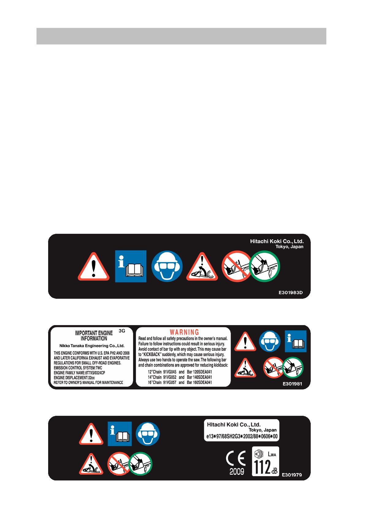
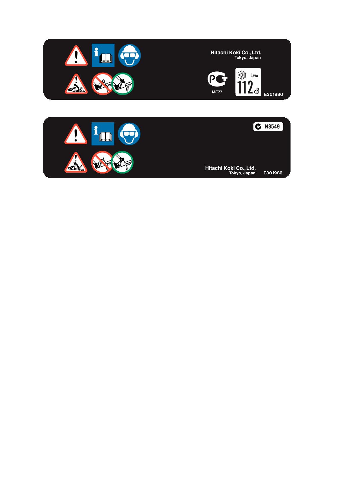
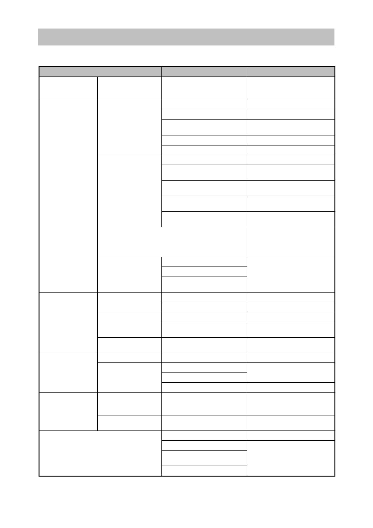
B. Caution plate
The Models CS 40EA (S) and CS 40EA (PS) are provided with a Warning Label (illustrated below) that lists
basic safety precautions on use. Carefully ensure that customers fully understand and follow these
precautions before using the tool.
[For Asia]
[For the USA]
[For Europe]
PRECAUTIONS ON SALES PROMOTION
-5-
[For Russia]
[For Australia]
C. Meaning of symbols
Read and understand the meaning of each symbol described in the Handling Instructions, and properly
instruct the users.
2. Thorough Instruction to the Customers
A. Starting and stopping procedures
Thoroughly instruct customers about the difference between the cold starting procedure and the hot
restarting procedure, and also the importance of starting with the throttle trigger positioned at the fast-idle
start position.
B. Fuel safety
An engine based on a two-cycle design powers the Models CS 40EA (S) and CS 40EA (PS). Instruct the
customers to use a mixture of gasoline and two-cycle oil at a ratio of 25 to 50:1 as fuel.
Instruct the customers to use a container intended for mixing gasoline and oil. The use of such resin
containers as poly tanks and PET bottles could cause failure by possibly melting into the mixture.
Fuel stored for a long time becomes degraded and deteriorated. Improper capping can also degrade fuel in
a single day, especially in summer. Instruct the customers not to store mixed fuel, but to only prepare the
required amount of mixture as needed.
C. Storage
Instruct customers to empty the fuel tank and perform idling until the engine stops, in order to burn up any
residual fuel in the carburetor before long term storage of the Models CS 40EA (S) and CS 40EA (PS). Should
any fuel remain in the carburetor, only the gasoline mixed in the fuel volatilizes during the storage period,
thereby clogging the fuel line with two-cycle oil. Consequently, the engine cannot be started the next time.
D. Chain oil
Instruct customers to use chain oil. Specially instruct them to use commercially available SAE20 or SAE30
engine oil.
Remind customers to always replenish the chain oil when replenishing the fuel.
E. Adjusting saw chain tension
Low tension of saw may damage the blades or guide bar, and even result in blades being detached under
extremely low tension. A new saw chain tends to quickly elongate; therefore, advise customers to
frequently adjust saw chain tension.
-6-
1. Troubleshooting and Correction
Situation Cause Measure
Starter handle
cannot be pulled.
The crankshaft does
not rotate.
Seizure of the piston ring
Seizure of the connecting
rod bearing
Disassembly and parts
replacement
No fuel in the tank Replenishment
Clogged fuel filter Cleaning or replacement
Faulty vent hole (check
valve) on the tank
Replacement
Dirt clogging the carburetor Cleaning
The plug does not
become wet with fuel
after repeated
starting operation.
Poor throttling Appropriate starting method
Dirty or faulty plug Cleaning or replacement
Improperly connected plug
cap
Inspection and replacement
Disconnected or improperly
connected high voltage cord
Repair or replacement
Ground connection of the
high voltage cord
Repair
No spark
Disconnected or faulty
ignition coil
Replacement
Short-circuited due to foreign matter between
the plug electrodes.
Removal of foreign matter: In
case of frequent occurrence,
disassemble and clean the
engine.
Faulty piston ring
Worn piston
Startup is
impossible.
No compression
Expired service life of the oil
seal
Parts replacement
Dirty or faulty plug Cleaning or replacement
Weak spark
Improper air gap Adjustment
Worn piston ring Replacement
Low compression
Expired service life of the oil
seal
Replacement
Idling stops
although startup is
possible.
Good spark and
compression
Revolutions too low for idling Adjustment
The engine stalls. Clogged fuel filter Cleaning or replacement
Muffler clogged with carbon
Clogged air cleaner
Cleaning
Starts, but when
accelerating …
Poor acceleration;
no increase in
revolutions
The chain brake is on. Release
Fluctuating
revolutions at high
speed
Dirt clogging the high-speed
fuel line
Cleaning
Starts, but …
Excessive fuel
consumption
Clogged air cleaner Cleaning
No oil in the tank Replenishment
Clogged oil filler port
Clogged oil filler port on the
guide bar
Chain oil is not discharged.
Clogged oil filter
Cleaning
TROUBLESHOOTING GUIDE
TROUBLESHOOTING GUIDE

-7-
This section describes repair, focusing on portions requiring frequent repair. Refer to TROUBLE
SHOOTING GUIDE in the previous section as the context for the following descriptions.
1. Precautions on Maintenance, Inspection and Repair
• The fuel used readily ignites; therefore, never bring the product near a flame.
• Use new gaskets at reassembly.
• Prior to disassembly for repair, remove the fuel and chain oil into separate containers, and allow the
engine to cool down.
• During repair, startup or running, use adequate care for portions posing the risk of burn injury or electric
shock, such as hot areas including the muffler, high voltage cord and spark plug.
• Before running the product with the chain bar and chain blades attached, make sure that there are no
other people nearby.
• Ensure proper ventilation when performing repair in a small room or other poorly ventilated space.
• After completing repair, always return the throttle lever to the idling position and set the stop switch to the
engine stop position.
2. Inspection Standards and Spark Plug Replacement
Model
Item
CS 40EA (S)
CS 40EA (PS)
Idling revolutions
min
-1
(rev./min)
2,900 to 3,300
No-load maximum revolutions
(with guide bar and chain blades)
min
-1
(rev./min)
13,000
Clutch engagement
min
-1
(rev./min)
3,900 to 4,700
Accelerating performance - Smooth acceleration
Gap between magneto rotor
and ignition coil
mm 0.3 to 0.4
Spark plug - NGK BPMR7A
Gap between spark plug
electrodes
mm 0.6 to 0.7
Height of carburetor metering lever -
Position 1.65 mm lower than
carburetor body surface
Chain blade type - OREGON 95VP
Chain blade pitch x gauge inch 0.325 x 0.050
No. of chain blade drive links - 56 (13”) , 64 (15”) , 66 (16”) , 72 (18”)
REPAIR AND MAINTENANCE GUIDE
REPAIR GUIDE
-8-
Broken piston ring Replacement
Seized piston or cylinder Replacement
Broken connecting rod needle
bearing
Replacement
Seized ball bearing Replacement
Magneto rotor contact with ignition
coil
Adjustment
Broken starter
Inspection/
replacement
Faulty starter pawl Inspection/
replacement
Stop switch not in the startup
position
Setting to the startup
position
Dirty or faulty spark plug Cleaning/inspection
Disconnected or improperly
connected high voltage cord and
other wiring
Inspection
Ground connection of the high
voltage cord and other wiring
Inspection
Disconnected or faulty ignition coil Replacement
Excessive gap between magneto
rotor circumference and ignition coil
Adjustment
Clogged fuel filter Cleaning/replacement
Cracked fuel pipe Replacement
Faulty tank vent hole (check valve) Replacement
Faulty pump diaphragm of the
carburetor
Replacement
Dirt clogging the carburetor Cleaning
Faulty piston ring Cleaning/replacement
Worn piston ring Replacement
Worn piston Replacement
Worn or damaged oil seal
Replacement
Clogged fuel filter Cleaning
Inadequate warm-up, especially in
cold weather
Warm-up
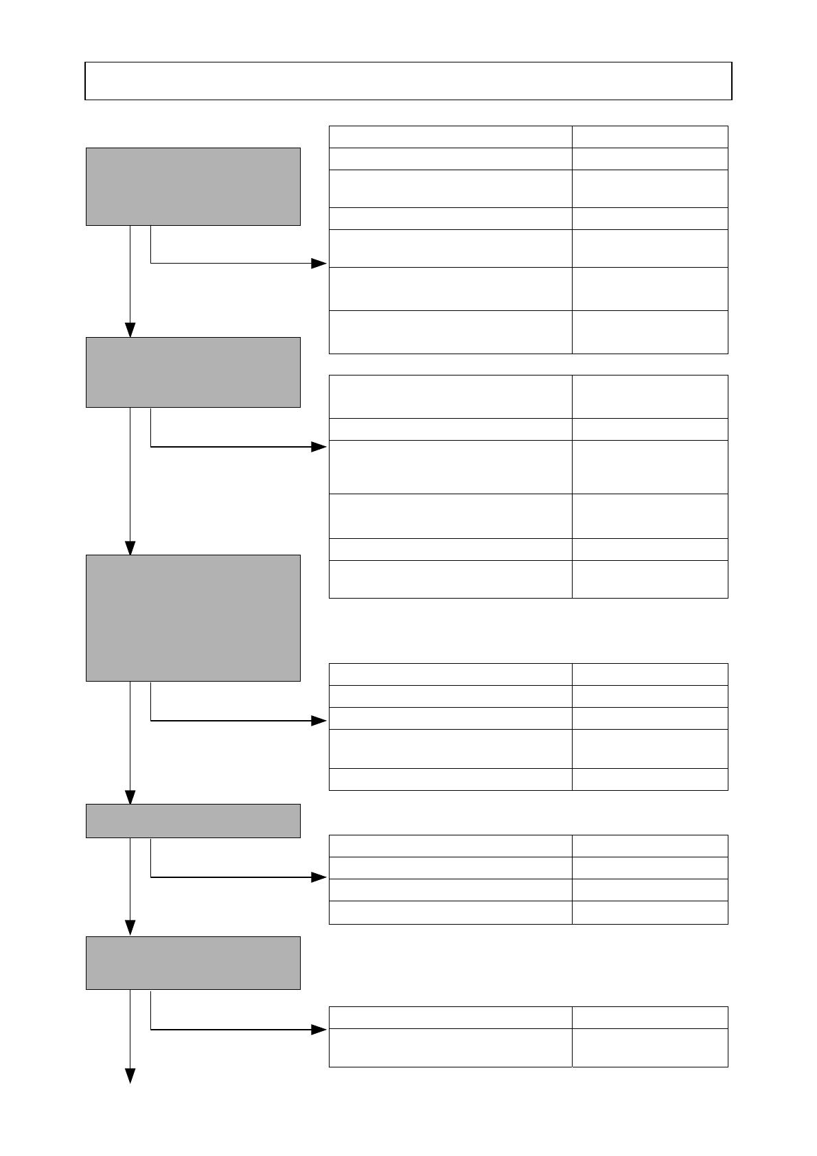
Repair flowchart
Impossible to pull
Pull the recoil starter.
Pulling is possible when you
feel a slight compression.
OK
Remove the spark plug to
check for sparks. Sparks are
generated.
No spark
Dry
Return the spark plug and plug
cap to the original positions, and
then perform proper startup
operation. Confirm that the tip of
the spark plug becomes wet with
fuel.
No compression
There is compression.There is compression.
The engine stalls
The engine starts, but when the
throttle is pulled …
OK
OK
OK
OK

-9-
Clogged cylinder exhaust port or
carbon clogging the muffler
Cleaning
Clogged air cleaner Cleaning
The chain brake is on. Release
Dirt clogging the carburetor
high-speed fuel line
Cleaning
Faulty carburetor pump diaphragm Replacement
Air intake from the gasket portions Inspection
Revolutions too low for idling Adjustment
Revolutions too low for idling Adjustment
Revolutions too low for idling Adjustment
Revolutions too high for idling Adjustment
Worn or faulty clutch Inspection/
replacement
High speed unavailable
Pulling the throttle lever
increases the speed.
Revolutions fluctuate
The engine stalls
Starts up, and when idling
mode is set …
Starts rotating
Starts up, and when idling
mode is set …
Starts up, and when idling
mode is set …
Starts up, and when idling
mode is set …
The chain blades start rotating
during idling.
When the revolutions
increase …
OK
OK
OK
The engine stalls
When the speed rapidly
decelerates from high speed…
The engine stalls
When the product is tilted
during idling…
OK
OK
-10-
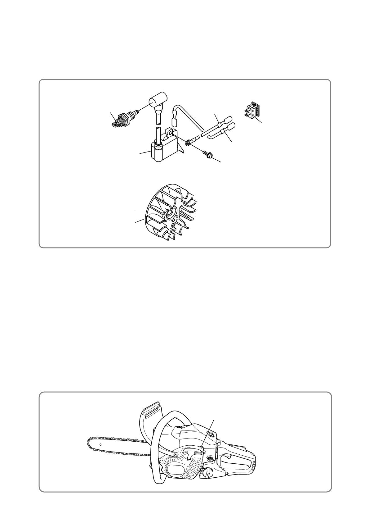
• Magneto
A
ss’y
• Spark plug
0.3mm to 0.4 mm
Hex. Socket Hd. Bolt (W/Flange)
M4 x 18 [51]
Ignition Coil [50]
Magneto Sub Ass’y [80]
High voltage cord
Ignited sparks
Spark plug
plug cap
• Checking for sparks
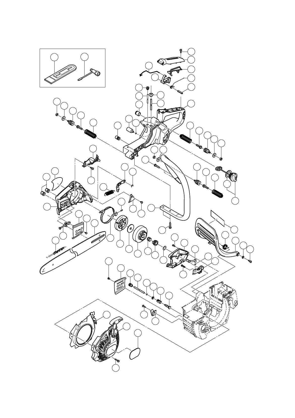
[Bold] numbers in the descriptions below correspond to item numbers in the Parts List and exploded
assembly diagram for the Models CS 40EA (S) and CS 40EA (PS).
Always stop the engine prior to disassembly or when replacing the saw chain.
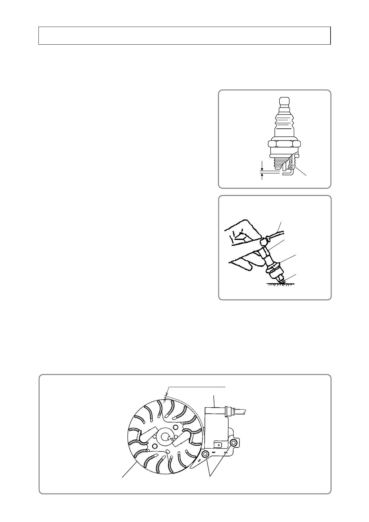
1. Checking the spark of the Spark plug
CAUTION: • Be careful not to touch the metallic portion of the
Spark Plug [13] when pulling the starter handle;
otherwise, you run the risk of electric shock.
• Carefully wipe off any fuel around the plug to
avoid a sudden breakout of fire.
(1) Remove the Spark Plug [13] from the Cylinder Ass’y [63].
Use a wire brush to clean off carbon accumulated on the
Spark Plug [13] electrodes, as needed. Adjust the gap
between the electrodes if necessary. Use a cloth to wipe off
any fuel on the electrodes. Remove fuel left in the Crank
Case Set [69] according to the procedure below.
(a) With the Spark Plug [13] removed from the Cylinder Ass’y [63]:
(b) Open the Choke Button [92] (by pushing it) and set the
S
top Switch [93] to the s
top position.
(c) Open the throttle (by pulling the Throttle Lever [122]).
(d) Pull the Starter Knob several times.
(2) Insert the Spark Plug [13] into the plug cap, and then place
the electrodes in contact with the metallic portion of the
engine. Under these conditions, set the Stop Switch [93] to
the startup position and pull the Starter Knob.
(3) When all the above are normal, the Spark Plug [13]
electrodes make a snapping sound to generate sparks.
2. Adjustment of air gap (clearance)
(1) Remove the Tapping Screw (W/Flange) D5 x 20 (Black) [39] and then the Recoil Starter [174].
(2) Loosen the two Hex. Socket Hd. Bolt (W/Flange) M4 x 18 [51] to the extent that the Ignition Coil [50] is
temporarily secured.
(3) Insert a clearance gauge between the magnetic steel portion around the perimeter of the Magneto Sub
Ass’y [80] and the Ignition Coil [50], and then adjust the position of the Ignition Coil [50] so that the
clearance becomes 0.3 mm to 0.4 mm.
(4) Under this condition, firmly tighten the Hex. Socket Hd. Bolt (W/Flange) M4 x 18 [51].
Gap between
electrodes
(0.6 to 0.7 mm)
Remove carbon.
Inspection and repair procedures
-11-
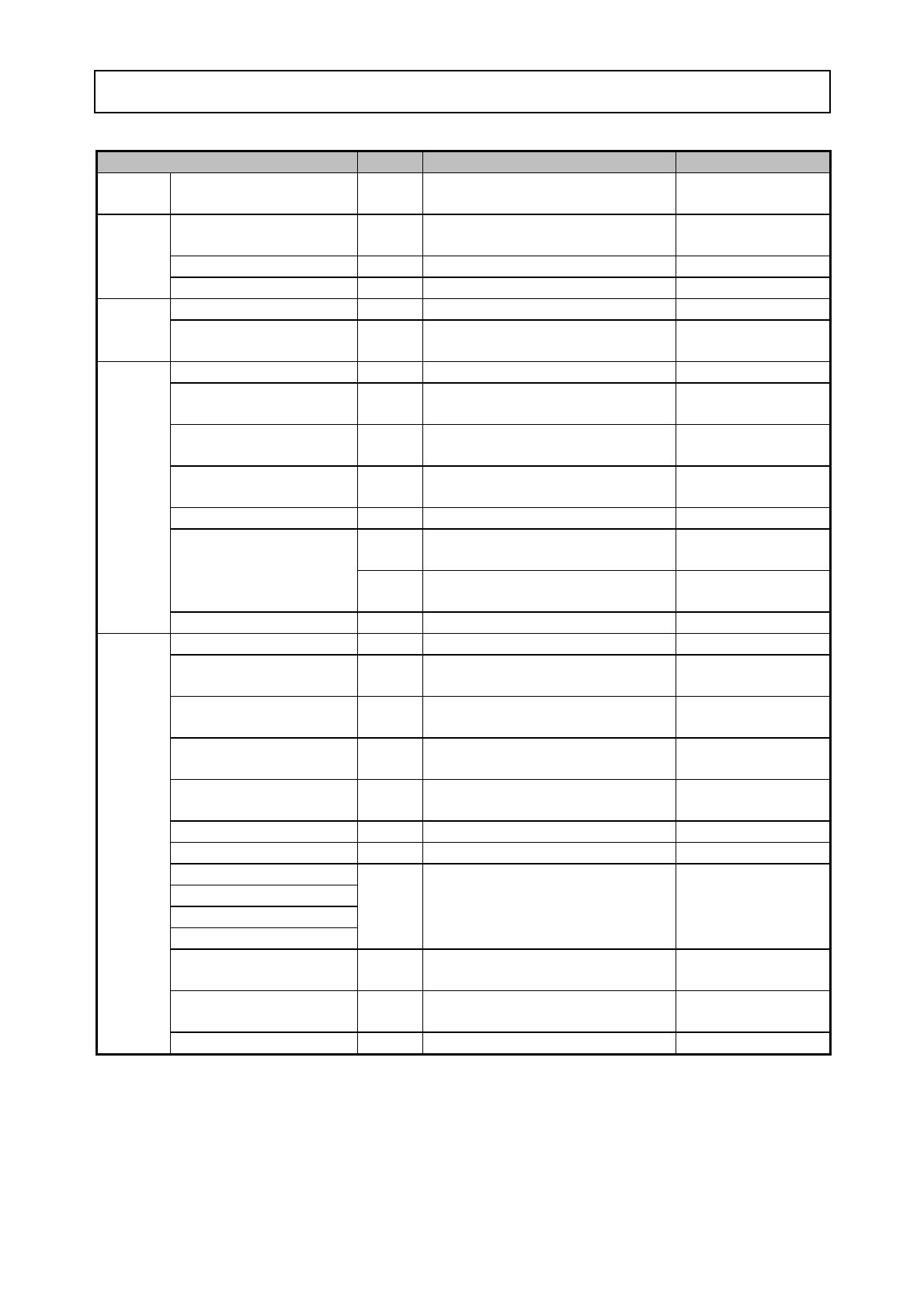
Idle Adjust Screw [32]
• Idle Adjust Screw
Magneto Sub Ass’y [80]
Stop Switch [93]
Hex. Socket Hd. Bolt (W/Flange)
M4 x 18 [51]
Cord (A) [47]
Spark Plug [13]
Ignition Coil [50]
Cord (B) [49]
3. Wiring diagram
The following diagram shows the wiring.
(1) Use Cord (A) [47] to connect the connector of the Ignition Coil [50] to the Stop Switch [93] .
(2) After connecting Cord (B) [49] to the connector of the Stop Switch [93], tighten the
Hex. Socket Hd. Bolt
(W/Flange) M4 x 18 [51]
inserted through the end of Cord (B) [49] into the Ignition Coil [50].
4. Adjustment of the Carburetor Ass’y
(1) Use the screw to adjust the Carburetor Ass’y [20]
• Idle Adjust Screw [32]
Use the screw for adjusting the amount of air during idling. Turning the screw clockwise increases
engine revolutions; turning it counterclockwise decreases engine revolutions.
(2) Standard setting of the carburetor
• Idle Adjust Screw [32]
2,900 to 3,300 min
-1
(rev./min)
(Confirm that the saw chain does not rotate.)
(3) Fine adjustment
• Idling adjustment
(a) By using the Idle Adjust Screw [32] , set revolutions so that the saw chain does not start rotating
while the engine runs stably.
(b) Set idling revolutions to 2,900 to 3,300 min
-1
(rev./min) by using the Idle Adjust Screw [32].
• Wiring diagram

-12-
Chain oil filler ports
5. Cleaning the chain oil filler ports
(1) Remove the Chain Bar and remove any sawdust clogging the filler ports.
(2) Remove sawdust from the groove on the Chain Bar (along which the saw chain travels) and from the
chain oil filler holes.
(1) With the Cylinder Ass’y [63], Piston (M) [67] and Piston Ring [65] removed, remove carbon accumulated
on the cylinder exhaust port and piston, and use gasoline to thoroughly clean the disassembled
components. Apply two-cycle dedicated oil to the bearings and sliding sections for reassembly.
(2) Make sure that the Clutch [158] is left-threaded in the Crank Shaft [77].
• Chain oil filler ports
• Chain oil filler holes
Chain oil
filler holes
Disassembly and reassembly
-13-
Ti
g
htenin
g
tor
q
ue
N•m {kgf•cm}
Location Quantity Screw type Tightening torque
Recoil
Starter
Recoil Starter [174] 3
Tapping Screw (W/Flange)
D5 x 20 (Black) [39]
2.4 to 3.4 {25 to 35 }
Ignition Coil [50] 2
Hex. Socket Hd. Bolt (W/Flange)
M4 x 18 [51]
2.5 to 4.5 { 26 to 46 }
Magneto Rotor [81] 1 Flywheel Nut [87]
11.8 to 12.8 { 120 to 130 }
Electrical
system
Spark Plug [13] 1 M14 10 to 15 { 102 to 153 }
Carburetor Ass'y [20] 2 Hex. Socket Hd. Bolt M5 x 45 [42] 2.5 to 3.0 { 26 to 31 }
Carburetor
Cleaner Support [40] 1
Tapping Screw (W/Flange) D5 x 20
(Black) [39]
2.2 to 2.8 {23 to 29 }
Clutch [158] 1M9
20.0 to 25.0 { 204 to 255 }
Crank Case Set [69]
Cylinder Ass'y [63]
8
Hex. Socket Hd. Bolt
(W/Sp. Washer) M5 x 20 [79]
5.0 to 6.0 { 51 to 61 }
Crank Case Set [69]
Engine Case Sub [90]
4
Seal Lock Hex. Socket Hd. Bolt M5
[76]
7.0 to 8.0 { 71 to 81 }
Scavenging Cover (A) [44]
Scavenging Cover (B) [11]
6 Machine Screw M4 x10 [10] 3.0 to 4.0 { 31 to 41 }
Intake [15] 2 Hex. Socket Hd. Bolt M5 x 12 [16] 5.0 to 6.0 { 51 to 61 }
2 Flange Nut M6 [58]
*1)
6.5 to 8.5 { 65 to 85 }
Muffler [59]
1
Hex. Socket Hd. Bolt
(W/Sp. Washer) M5 x 16 [60]
*2)
6.5 to 8.5 { 65 to 85 }
Engine
Muffler Protector [54] 3 Hex. Socket Bolt (SUS) M4 [53] 4.0 to 4.5 { 41 to 46 }
Antivibration Spring [115] 2 Flanged Tapping Screw D6 [114] 3.5 to 4.5 {35 to 45 }
Spring Holder [113]
Spring Holder [131]
3Nut M6 [111] 4.0 to 5.0 { 41 to 51 }
Front Handle [142] 4
Tapping Screw (W/Flange)
D5 x 25 (Black) [134]
1.5 to 2.0 {15 to 20 }
Antivibration Spring [133] 1
Hex. Socket Hd. Bolt (W/Flange)
M6 x 20 [132]
6.0 to 9.0 {61 to 92 }
Chain Catcher [172] 1
Flanged Tapping Screw
D5 x 15 [171]
2.4 to 3.4 {25 to 35 }
Cylinder Cover Ass'y [7] 3 Cover Set Bolt [5] 2.3 to 2.7 {24 to 27 }
Oil Pump [145] 1 Machine Screw M4 x 16 [164] 1.5 to 2.0 {15 to 20 }
Oil Pump Cover [143]
Brake Handle [148]
Brake Link Cover [135]
Rear Handle Grip [126]
8
Tapping Screw (W/Flange)
D4 x 16 (Black) [125]
1.5 to 2.5 {15 to 25 }
Guide Plate (A) [165]
Guide Plate (B) [154]
2 Tapping Screw D3 x 8 [155] 0.6 to 1.0 {6 to 10 }
Brake Band Plate [140] 1
Tapping Screw (W/Flange)
D4 x 16 (Black) [125]
1.5 to 2.5 {15 to 25 }
Other
Starter Pawl [84] 2 Step Bolt [85] 6.0 to 9.0 { 61 to 92 }
*1): After running, retighten 17.5 to 18.5 N•m {179 to 189 kgf•cm}.
*2): After running, retighten 9.5 to 10.5 N•m {97 to 107 kgf•cm}.
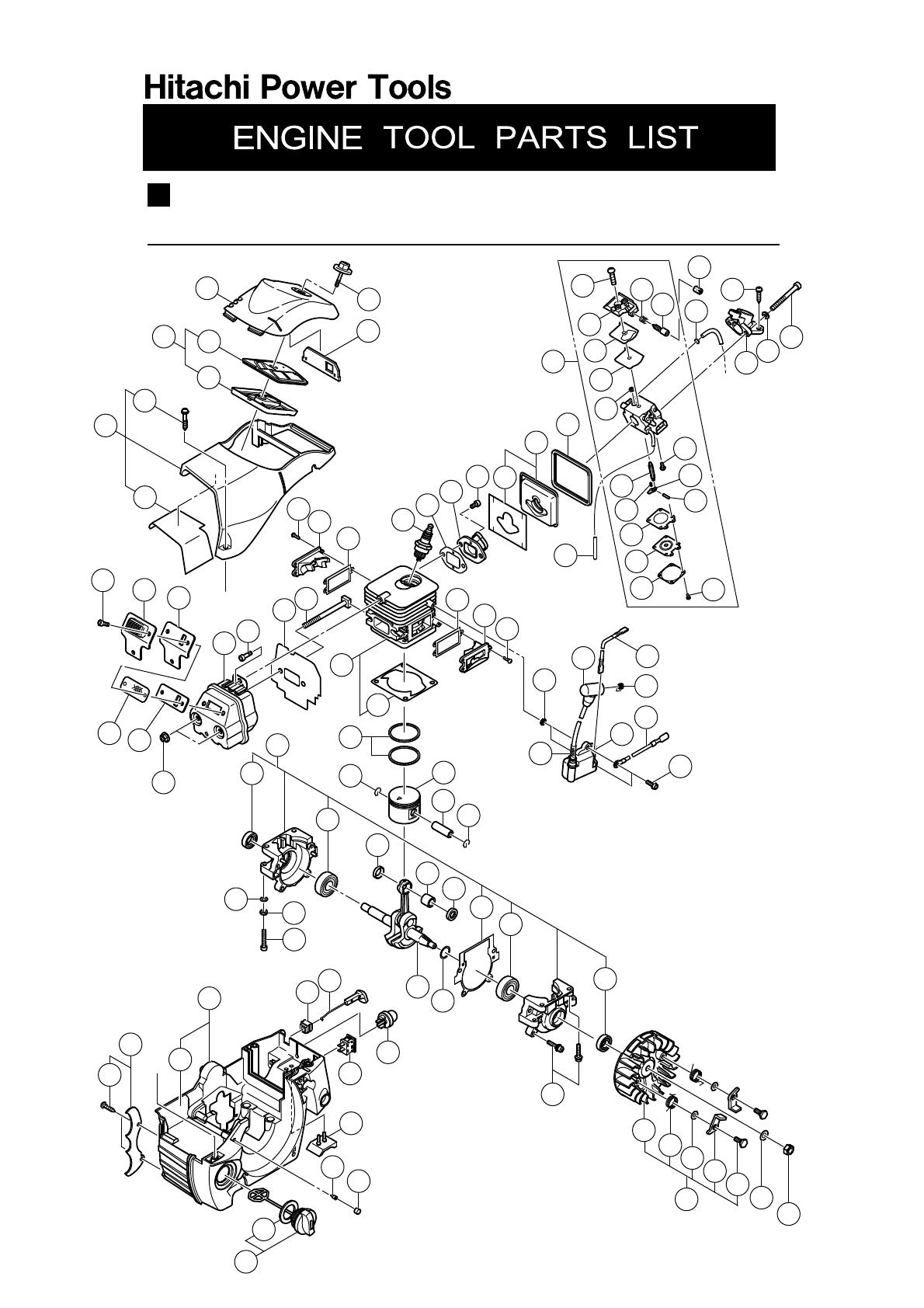
Model CS 40EA
ENGINE CHAIN SAW
LIST NO. E079
(E1)
2010 8 18
A
A
B
1
3
5
8
9
7
10
11
12
63
13
14
15
16
18
43
21
22
23
24
28
29
30
31
32
38
39
42
41
40
53
54
55
56
57
58
64
65
66
12
10
66
70
41
75
76
71
71
72
68
67
73
72
77
74
70
81
82
83
84
85
86
87
44
45
46
47
48
50
49
51
90
91
92
93
94
95
96
97
98
99
79
20
80
88
2
4
19
78
39
25
26
27
33
34
35
37
36
52
59
60
62
89
61
6
17
69
•
••
•
8 - 10
CS 40EA
- 2 -
B
38
113
114
115
115
113
114
116
117
120
119
118
121
126
125
127
122
128
129
111
98
99
123
124
130
38
125
41
38
39
131
132
133
142
135
125
136
137
138
140
141
134
148
146
149
151
150
153
152
154
155
156
157
139
158
159
160
161
162
163
125
143
164
155
165
166
167
168
169
170
171
172
173
174
175
501
502
134
147
145
144
112
112
112
111
111

PART
S
CS 40EA
DESCRIPTION REMARKS
1 669-8424 CLEANER COVER 1
2 669-6908 CLEANER ELEMENT (B) 1
3 669-6907 CLEANER ELEMENT (A) 1
4 669-6891 CLEANER ELEMENT ASS'Y 1 INCLUD. 2, 3
5 669-6903 COVER SET BOLT 3
6 669-8520 ALUMINUM TAPE (A) 1
* 7 669-8462 CYLINDER COVER ASS'Y 1 INCLUD. 5, 6
* 7 669-8519 CYLINDER COVER ASS'Y 1 INCLUD. 5, 6 FOR EUROPE, USA, CAN
* 8 669-8425 CLEANER KNOB (VERMILION) 1
* 8 669-8438 CLEANER KNOB (GREEN) 1 FOR USA, CAN
9 669-6904 SHUTTER PLATE 1
10 949-216 MACHINE SCREW M4 X 10 (10 PCS.) 6
11 669-8407 SCAVENGING COVER (B) 1
12 669-6852 COVER PACKING 2
* 13 668-5782 SPARK PLUG BPMR7A 1
* 13 669-8432 SPARK PLUG BPM-7A 1
14 669-6895 INTAKE PACKING 1
15 669-8419 INTAKE 1
16 949-765 HEX. SOCKET HD. BOLT M5 X 12 (10 PCS.) 2
17 669-8524 ALUMINUM TAPE (B) 1
18 669-8461 CARBURETOR INSULATOR ASS'Y 1 INCLUD. 17
19 669-6896 CARB. INSULATOR RUBBER 1
20 669-8433 CARBURETOR ASS'Y 1 INCLUD. 21-36
21 668-5210 SCREW 1
22 PUMP BODY 1
23 668-5212 PUMP GASKET 1
24 668-5213 PUMP DIAPHRAGM 1
25 668-4700 INLET SCREEN 1
26 668-5215 NEEDLE VALVE 1
27 669-0873 VALVE SPRING 1
28 668-5220 DIAPHRAGM PACKING 1
29 668-4690 METERING DIAPHRAGM COMP. 1
30 668-5222 DIAPHRAGM COVER 1
31 669-0766 IDLE ADJUST SPRING 1
32 668-5298 IDLE ADJUST SCREW 1
33 668-5218 HINGE PIN SET SCREW 1
34 668-5217 CONTROL LEVER 1
35 668-5219 HINGE PIN 1
36 668-5223 SET SCREW 4
37 668-5224 IDLE SPONGE 1
38 668-5311 CLIP 4
39 302-089
TAPPING SCREW (W/FLANGE) D5 X 20 (BLACK) 6
40 669-8427 CLEANER SUPPORT 1
41 668-5408 WASHER 5 7
42 669-6317 HEX. SOCKET HD. BOLT M5 X 45 2
43 669-8434 FUEL PIPE 1
44 669-8406 SCAVENGING COVER (A) 1
45 668-4600 WASHER 2
46 669-8435 PLUG CAP 1
47 668-5365 CORD (A) 1
8 - 10 - 3 -
*ALTERNATIVE PARTS
ITEM
NO.
NO.
USED
CODE NO.
ITEM
NO.
NO.
USED
CODE NO.

PARTS CS 40EA
DESCRIPTION REMARKS
48 669-8436 METAL FITTING OF PLUG CAP 1
49 668-5338 CORD (B) 1
50 669-8416 IGNITION COIL 1
51 669-6326
HEX. SOCKET HD. BOLT (W/FLANGE) M4 X 18 2
52 669-8457 CORD INSULATION TUBE 1
53 669-8442 HEX. SOCKET BOLT(SUS) M4 3
54 669-8458 MUFFLER PROTECTOR 1
55 669-8459 MUFFLER PROTECTOR PACKING 1
56 669-6874 MUFFLER GAUZE 1
57 669-8460 EXHAUST PLATE 1
58 329-934 FLANGE NUT M6 2
* 59 669-8410 MUFFLER 1 FOR EUROPE, USA, CAN, JPN
* 59 669-8411 MUFFLER 1
60 305-574
HEX. SOCKET HD. BOLT (W/SP.WASHER) M5 X 16 1
61 669-8412 MUFFLER PACKING 1
62 669-8437 SQUARE HEAD BOLT M6 2
63 669-8430 CYLINDER ASS'Y 1 INCLUD. 64
64 669-6864 CYLINDER PACKING 1
65 669-6858 PISTON RING 2
66 669-6854 CIR CLIP 2
67 669-8521 PISTON (M) 1
68 669-6855 PISTON PIN 1
69 669-8441 CRANK CASE SET 1 INCLUD. 70, 71, 74
70 668-4607 OIL SEAL TB 12227 2
71 668-5328 BALL BEARING 2
72 669-6856 PISTON PIN COLLAR 2
73 669-8445 NEEDLE BEARING (A) 1
74 669-6863 CRANK CASE PACKING 1
75 949-454 SPRING WASHER M5 (10 PCS.) 4
76 668-5412 SEAL LOCK HEX. SOCKET HD. BOLT M5 4
77 669-6853 CRANK SHAFT 1
* 78 669-6865 SHIM 1 T 0.2
* 78 669-6866 SHIM 1 T 0.3
* 78 669-6867 SHIM 1 T 0.4
79 305-583
HEX. SOCKET HD. BOLT (W/SP.WASHER) M5 X 20 8
80 669-8414 MAGNETO SUB ASS'Y 1 INCLUD. 81-85
81 669-8415 MAGNETO ROTOR 1
82 669-8417 STARTER PAWL SPRING 2
83 669-6857 WASHER 0.8 2
84 669-6877 STARTER PAWL 2
85 669-6878 STEP BOLT 2
86 669-6880 BOLT WASHER D7 1
87 669-6879 FLYWHEEL NUT 1
88 669-6329 SPIKE SET 1 INCLUD. 39
89 669-8523 ALUMINUM TAPE 1
90 669-8448 ENGINE CASE SUB 1
91 668-5369 CHOKE ROD RUBBER 1
* 92 669-8463
CHOKE BUTTON 1
* 92 669-8464 CHOKE BUTTON 1 FOR USA, CAN
93 668-5364 STOP SWITCH 1
- 4 - 8 - 10
*ALTERNATIVE PARTS
NO.
USED
CODE NO.
ITEM
NO.
CODE NO.
ITEM
NO.
/