Binks SV100
™
HVLP
Pressure Feed Spray Gun
7041-6931-1
The following instructions provide the necessary
information for the proper maintenance of the Binks
SV100 pressure feed spray gun. Please read and
understand all the information in this document in order
to get the maximum performance from your new SV100
pressure spray gun.
The SV100 spray gun is the result of quality engineering
and development activity. The result is an ergonomic
product with reduced triggering effort and fine
atomization. The HVLP air cap has been specifically
designed to comply with local regulatory air quality
restrictions. The specification table details the operating
parameters of the gun to achieve those compliant
conditions. In addition, the relatively low air flow rate of
the SV100 spray gun will help in containing overspray.
The SV100 spray gun should be operated under the safety
directions outlined in this literature. Your safety and the
safety of others depend on your thorough understanding
of the material contained on the Part Sheet.
If you have any questions or do not understand the
content in this literature, call your nearest service
representative.
Replaces
Part Sheet
77-2874R-6
Part
Sheet
77-2874R-7
SPECIFICATIONS
Max. Air Pressure: 175psi/12bar
For HVLP Compliance: 26 psi inlet pressure delivers
(with SV100-693K cap) 10 psi air cap pressures at
12 cfm air volume
For HVLP Compliance: 20 psi inlet pressure delivers
(with SV100-690K cap) 10 psi air cap pressures at
6.5 cfm air volume
Gun Body: Cast Aluminum
Fluid Path: Stainless Steel
Fluid Nozzle: Stainless Steel
Fluid Needle: Stainless Steel
Fluid Inlet Size: 3/8" NPS(M)
Air Inlet Size; 1/4" NPS(M)
Gun Weight: 1.12 lbs. (507 g)
Binks SV100
™
is a trademark of Binks
®
.

2
Warning
!
In this part sheet, the words WARNING, CAUTION and NOTE are used to emphasize important safety information as follows:
CAUTION
Hazards or unsafe practices which could
result in minor personal injury, product
or property damage.
!
WARNING
Hazards or unsafe practices which could
result in severe personal injury, death or
substantial property damage.
!
NOTE
Important installation, operation or
maintenance information.
Read the following warnings before using this equipment.
READ THE MANUAL
Before operating finishing equipment, read and
understand all safety, operation and maintenance
information provided in the operation manual.
AUTOMATIC EQUIPMENT
Automatic equipment may start suddenly without
warning.
INSPECT THE EQUIPMENT DAILY
Inspect the equipment for worn or broken parts
on a daily basis. Do not operate the equipment
if you are uncertain about its condition.
NEVER MODIFY THE EQUIPMENT
Do not modify the equipment unless the
manufacturer provides written approval.
KNOW WHERE AND HOW TO SHUT OFF THE
EQUIPMENT IN CASE OF AN EMERGENCY
PRESSURE RELIEF PROCEDURE
Always follow the pressure relief procedure in the
equipment instruction manual.
NOISE HAZARD
You may be injured by loud noise. Hearing
protection may be required when using this
equipment.
STATIC CHARGE
Fluid may develop a static charge that must be
dissipated through proper grounding of the
equipment, objects to be sprayed and all other
electrically conductive objects in the dispensing
area. Improper grounding or sparks can cause a
hazardous condition and result in fire, explosion
or electric shock and other serious injury.
FIRE AND EXPLOSION HAZARD
Never use 1,1,1-trichloroethane, methylene
chloride, other halogenated hydrocarbon solvents
or fluids containing such solvents in equipment
with aluminum wetted parts. Such use could
result in a serious chemical reaction, with the
possibility of explosion. Consult your fluid
suppliers to ensure that the fluids being used are
compatible with aluminum parts.
WEAR SAFETY GLASSES
Failure to wear safety glasses with side shields
could result in serious eye injury or blindness.
DE-ENERGIZE, DISCONNECT AND LOCK OUT ALL
POWER SOURCES DURING MAINTENANCE
Failure to De-energize, disconnect and lock out
all power supplies before performing equipment
maintenance could cause serious injury or death.
OPERATOR TRAINING
All personnel must be trained before operating
finishing equipment.
EQUIPMENT MISUSE HAZARD
Equipment misuse can cause the equip ment to
rupture, malfunction, or start unexpectedly and
result in serious injury.
KEEP EQUIPMENT GUARDS IN PLACE
Do not operate the equipment if the safety
devices have been removed.
PROJECTILE HAZARD
You may be injured by venting liquids or gases
that are released under pressure, or flying debris.
PINCH POINT HAZARD
Moving parts can crush and cut. Pinch points are
basically any areas where there are moving parts.
FOR FURTHER SAFETY INFORMATION REGARDING BINKS AND DEVILBISS EQUIPMENT,
SEE THE GENERAL EQUIPMENT SAFETY BOOKLET (77-5300).
IT IS THE RESPONSIBILITY OF THE EMPLOYER TO PROVIDE THIS INFORMATION TO THE OPERATOR OF THE EQUIPMENT.
CA PROP
65
PROP 65 WARNING
WARNING: This product contains chemicals known
to the State of California to cause cancer and
birth defects or other reproductive harm.

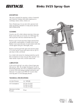
TYPES OF INSTALLATION
3
5/16”
1/4”
Only 43 PSI at gun inlet
25 feet of 1/4” I.D. hose causes
a drop of 17 PSI between the
air supply and the gun.
(NOT RECOMMENDED)
54 PSI at gun inlet
25 feet of 5/16” I.D. hose
causes a drop of 6 PSI
between the air supply
and the gun. For this reason
Binks recommends the use
of 5/16” hose.
(RECOMMENDED)
With 60 psi applied at air supply
PRESSURE CUP HOOKUP
(Figure 1)
For fine finishing with limited spray-
ing. Air pressure for atomization is
regulated at extractor; fluid pressure
at cup regulator. Pressure cup is also
available less regulator.
PRESSURE TANK HOOKUP
(Figure 2)
For medium production spraying
(single regulator). Air pressure for
atomization is regulated at extractor,
fluid pressure at tank regulator.
PRESSURE TANK WITH
2 REGULATORS (Figure 3)
The pressure to the tank is regulated
by the first regulator. The pressure
for
atomization is regulated by the sec-
ond regulator.
PRESSURE CIRCULATING
HOOKUP (Figure 4)
For heavy production spraying.
Air pressure atomization regulated
at separator filter. Fluid pressure
regulated at fluid regulator.
AIR PRESSURE
Atomizing pressure must be set prop-
erly to allow for the drop in air pres-
sure between the regulator and the
spray gun.
Separator filter is important.
Achieving a fine spray finish without the use of a good separator filter is virtually impossible.
A regulator / separator filter serves a double purpose. It eliminates blistering and spotting by
keeping air free of oil and water, and it gives precise air pressure control at the gun.
Binks recommends using Model HFRL-508 Separator Filter / Regulator. See your local
distributor for other models.
Cross section view
showing comparison of inside
hose diameters (actual size).
60 lbs. regulated pressure
Fluid Pressure Cup
FIG 2
Air
Fluid
Outlet
Air
Inlet
Separator Filter
Fluid
Pressure
Tank
FIG 3
FIG 4
Fluid
Regulator
Air Supply
Air Supply
Fluid
Pressure
Tank
Separator
Filter
Air
FIG 1
Air
Cup Regulator
Separator
Filter
Fluid

4
OPERATION AND MAINTENANCE FOR BINKS SV100
™
HVLP SPRAY GUN
Your new SV100 HVLP spray gun is
exceptionally rugged in construction and
is built to stand up under hard, continu-
ous use. However, like any other fine
precision instrument, its most efficient
operation depends on a knowledge of its
construction, operation and mainte-
nance. Properly handled and cared for, it
will produce beautiful, uniform finishing
results long after other spray guns have
worn out.
SET-UP FOR SPRAYING
Connecting Gun To Air Hose
Air should be supplied by a suitable
length of 5/16" diameter air hose fitted
with a 1/4" NPS(f) connection at gun
end. For hose lengths over 50', use 3/8"
diameter hose.
Connecting Gun To Fluid Hose
Fluid should be supplied by a suitable
length of 3/8" diameter fluid hose fitted
with a 5/16" NPS(f) connection at gun
end. 1/4" diameter hose is recommended
for use with low viscosity fluids. (Fluid
hoses of different composition are avail-
able for special fluids.)
SPRAY GUN CLEANING
INSTRUCTIONS
In certain states it is now against the law
to spray solvents containing Volatile
Organic Compounds (VOC)’s into the
atmosphere when cleaning a spray gun.
In order to comply with these air quality
laws Binks recommends one of the fol-
lowing two methods to clean your spray
finishing equipment:
1. Spray solvent through the gun into a
closed system. An enclosed unit or
spray gun cleaning station condenses
solvent vapors back into liquid form
which prevents escape of VOC’s into
the atmosphere.
2. Place spray gun in a washer type
cleaner. This system must totally
enclose the spray gun, cups, nozzles
and other parts during washing, rins-
ing and draining cycles. This type of
unit must be able to flush solvent
through the gun without releasing
any VOC vapors into the atmosphere.
Additionally, open containers for storage
or disposal of solvent or solvent-con-
taining cloth or paper used for surface
preparation and clean-up may not be
used. All containers shall be nonabsor-
bent.
Pointers On Cleaning
When used with 1 quart cup, relieve
pressure in the cup. Then unscrew,
empty and carefully rinse cup out with
thinners. Place clean thinners in the cup
and spray this through the gun until it is
clean. Blow air through gun to dry it.
When Used With Pressure
Container
Shut off air supply to container and
release the pressure on the container.
Loosen retaining ring two turns, hold a
piece of cloth wadded in the hand over
the gun nozzle and pull the trigger. The
air will back up through the fluid nozzle
and force the fluid out of the hose into
the container. Empty container. Put
enough thinner into the container to
wash hose and gun thoroughly and spray
this through the gun until it is clean.
Then blow out the fluid hose to dry it
and remove all traces of fluid by attach-
ing it to the air line.
When used with Paint
Circulating System
Shut off fluid supply and remove fluid
hose from gun. Clean gun with compatible
solvent. To ensure a clean air supply to
your spray gun, use separator filter.
See your Binks distributor for the
correct model.
CAUTION
All parts on a spray gun should be
screwed in hand tight at first; this
will avoid the possibility of cross
threading the parts. If the parts
cannot be turned by hand easily,
make sure you have the correct
parts, unscrew, realign, and try
again. NEVER use undue force in
mating parts.
!

5
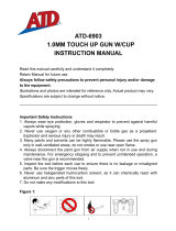
BINKS SV100
™
HVLP PRESSURE FEED SPRAY GUN
ITEM PART
NO. NO. DESCRIPTION QTY.
1 SV100-693K AIR CAP .............................................. 1
1a SV100-690K AIR CAP (not shown) ......................... 1
2
★ — FLUID TIP 1.1 mm ............................... 1
2a
★ — FLUID TIP 1.4 mm (not shown) .......... 1
2b• — FLUID TIP 1.8 mm (not shown) .......... 1
3
★■ — GASKET ............................................... 1
4
k — BAFFLE ................................................ 1
5
★■ •t — GASKET ............................................... 1
6
★■ •t — PACKING ............................................. 1
8 — GUN BODY ......................................... 1
9
k — SPRAY PATTERN VALVE ..................... 1
10
■ — U-CUP SEAL ........................................ 2
11
■ — AIR VALVE SEAT ................................. 1
12 — AIR VALVE STEM ................................ 1
13
■ — AIR VALVE SPRING ............................. 1
14 — AIR VALVE BUSHING .......................... 1
15
★ — FLUID NEEDLE 1.1 mm ....................... 1
15a
★ — FLUID NEEDLE 1.4 mm (not shown) .. 1
15b• — FLUID NEEDLE 1.8 mm (not shown) .. 1
16
★• — FLUID NEEDLE SPRING ....................... 1
17 — FLUID ADJUSTMENT KNOB ............... 1
ITEM PART
NO. NO. DESCRIPTION QTY.
18 — NIPPLE ................................................. 1
19 SGK-457 AIR ADJUSTING VALVE ASSEMBLY ... 1
20 — FLUID NIPPLE ...................................... 1
21 — WASHER ............................................. 1
22 — NUT ..................................................... 1
23 — FLUID NIPPLE ASSEMBLY ................... 1
24 — TRIGGER PIN ASSEMBLY .................... 1
25 — TRIGGER ............................................. 1
26
■ — ASSEMBLY TOOL ................................ 1
★ K-5052 Pressure Gun Fluid Tip and Needle Replacement Kit
(includes 1.1 and 1.4 mm tips & needles)
• K-5052-18 Pressure Gun Fluid Tip and Needle Replacement Kit
(1.8 mm)
k SGK-454-K Spray Pattern Valve and Baffle
■ K-5057 Soft Parts Kit
t SGK-537-K 5 ea. Packings and Baffle Gasket
NOTE: Use 1.1 mm fluid tip/needle with low viscosity materials.
Use 1.4 mm fluid tip/needle with high viscosity materials.
PARTS LIST
(When ordering, please specify Part No.)
TEST AIR CAP KITS
(sold separately)
54-5654 SV100-693
54-5657 SV100-690

6
SPRAY TECHNIQUE
The first requirement for a good resultant fin-
ish is the proper handling of the gun. The gun
should be held perpendicular to the surface
being covered and moved parallel with it. The
stroke should be started before the trigger is
pulled and the trigger should be released
before the stroke is ended. This gives accurate
control of the gun and fluid.
The distance between gun and surface should
be 6 to 8 inches depending on fluid and
atomizing pressure. The fluid deposited
should always be even and wet. Lap each
stroke over the preceding stroke to obtain a
uniform finish.
GENERAL SPRAY
INSTRUCTIONS
To reduce overspray and obtain maximum
efficiency, always spray with the lowest possi-
ble fluid/air pressure that produces an accept-
able spray pattern.
Excessive atomizing air pressures can
increase overspray, reduce transfer efficiency,
and with some materials, result in poor finish
quality from dry spray. Atomizing air pressures
should not exceed 10 psi. Compliance can be
checked by having a pressure no greater than
26 psi at the gun inlet.
For best results, use 3 to 6 psi fluid pressure.
Higher than 6 psi fluid pressure may be
required for heavy-bodied materials. Low fluid
pressures will produce a narrower than normal
spray pattern. Generally use up to 20 psi air at
gun inlet. Unusually heavy, difficult to
atomize fluids may require up to 26 psi air at
gun inlet.
CONTROLLING THE FAN SPRAY
The fan spray is controlled by means of the
side port control assembly. Turning this con-
trol clockwise until it is closed will give a
round spray; turning it counterclockwise will
widen the spray into a fan shape. The fan
spray can be turned anywhere through 360 °
by positioning the air nozzle relative to the
gun. To accomplish this, loosen retaining ring,
position nozzle, then tighten retaining ring.
CONTROLLING THE FLUID FLOW
When used with a pressure assisted cup, an
increase in air pressure will increase the rate
of flow. When fed from a pressure supply, an
increase in the fluid pressure will increase the
rate of flow. Correct fluid nozzle size should
be selected for correct fluid flow rate. The
fluid control knob may be used for minor
adjustment of fluid flow.
AIR NOZZLE, FLUID NOZZLE,
FLUID NEEDLE
1. All nozzles and needles are precision
made. They should be handled with care.
2. Do not make any alterations in the gun.
To do so could cause finishing difficulties.
3. To clean nozzles, soak them in solvent to
dissolve any dried material, then blow
them clean with air.
4. Do not probe any of the holes in the
nozzles with metal instruments.
If probing is necessary, use only a
tool that is softer than brass.
TROUBLESHOOTING
Faulty Spray
A faulty spray pattern is often caused by
improper cleaning resulting in dried materials
around the fluid nozzle tip or in the air nozzle.
Soak these parts in thinners to soften the dried
material and remove with a brush or cloth.
If either the air nozzle or fluid nozzle are
damaged, these parts must be replaced before
perfect spray can be obtained.
Intermittent Spray
If the spray flutters, it is caused by one of the
following faults:
1. Insufficient fluids available. Check supply
and replenish if necessary.
2. Pressure vent tube from gun body to
pressure pot is loose or leaking.
3. Check valve in pressure relief valve is
stuck or blocked.
4. Pressure pot cover not sufficiently tight or
cover gasket defective.
5. Insufficient fluid pressure from standard
pressure pots.
6. Pickup tube in pressure pot bottoming out
if 1-gallon pot is used.
NOTE
To reduce overspray and obtain
maximum efficiency always spray
with the lowest possible atomizing
air pressure.
CAUTION
Never use metal instruments to clean
the air or fluid nozzles. These parts
are carefully machined and any dam-
age to them will cause faulty spray.
!
OPERATING THE SV100
HVLP SPRAY GUN
BINKS SV100
™
HVLP PRESSURE FEED SPRAY GUN

7
NOTES

9/13 © 2013 Binks All rights reserved. Printed in U.S.A.
U.S.A./Canada Customer Service
195 Internationale Blvd.
Glendale Heights, IL 60139
630-237-5000
Toll Free Customer Service
and Technical Support
800-992-4657
Toll Free Fax
888-246-5732
Binks Sales and Service: www.binks.com
WARRANTY
This product is covered by Binks’ 1 Year Limited Warranty.
77-2874R-7 Revisions: (P5) Added Test Air Caps.
/