
Refer All Communications to the Nearest
Ingersoll–Rand Office or Distributor.
Ingersoll–Rand Company 1999
Printed in U.S.A.
03542354
Form P7309
Edition 3
August, 1999
OPERATION AND MAINTENANCE MANUAL FOR
99S VERTICAL AIR SANDERS
Series 99S Vertical Air Sanders are designed for heavy duty sanding and polishing
operations where space limitations are a factor.
Ingersoll–Rand is not responsible for customer modification of tools for applications on
which Ingersoll–Rand was not consulted.
IMPORTANT SAFETY INFORMATION ENCLOSED.
READ THIS MANUAL BEFORE OPERATING TOOL.
IT IS THE RESPONSIBILITY OF THE EMPLOYER TO PLACE THE INFORMATION
IN THIS MANUAL INTO THE HANDS OF THE OPERATOR.
FAILURE TO OBSERVE THE FOLLOWING WARNINGS COULD RESULT IN INJURY.
PLACING TOOL IN SERVICE
• Always operate, inspect and maintain this tool in
accordance with American National Standards
Institute Safety Code for Portable Air Tools
(ANSI B186.1).
• For safety, top performance, and maximum durability
of parts, operate this tool at 90 psig (6.2 bar/620 kPa)
maximum air pressure at the inlet with 3/4” (19 mm)
inside diameter air supply hose.
• Always turn off the air supply and disconnect the air
supply hose before installing, removing or adjusting
any accessory on this tool, or before performing any
maintenance on this tool.
• Do not use damaged, frayed or deteriorated air hoses
and fittings.
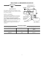
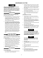
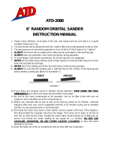
• Be sure all hoses and fittings are the correct size and
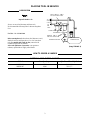
are tightly secured. See Dwg. TPD905–1 for a typical
piping arrangement.
• Always use clean, dry air at 90 psig maximum air
pressure. Dust, corrosive fumes and/or excessive
moisture can ruin the motor of an air tool.
• Do not lubricate tools with flammable or volatile
liquids such as kerosene, diesel or jet fuel.
• Do not remove any labels. Replace any damaged label.
USING THE TOOL
• Always wear eye protection when operating or
performing maintenance on this tool.
• Always wear hearing protection when operating this
tool.
• Keep hands, loose clothing and long hair away from
rotating end of tool.
• Anticipate and be alert for sudden changes in motion
during start up and operation of any power tool.
• Keep body stance balanced and firm. Do not
overreach when operating this tool. High reaction
torques can occur at or below the recommended air
pressure.
• Check for excessive speed and vibration before
operating.
• Tool shaft may continue to rotate briefly after throttle
is released.
• Air powered tools can vibrate in use. Vibration,
repetitive motions or uncomfortable positions may be
harmful to your hands and arms. Stop using any tool
if discomfort, tingling feeling or pain occurs. Seek
medical advice before resuming use.
• Use accessories recommended by Ingersoll–Rand.
• This tool is not designed for working in explosive
atmospheres.
• This tool is not insulated against electric shock.
The use of other than genuine Ingersoll–Rand replacement parts may result in safety hazards, decreased tool performance, and
increased maintenance, and may invalidate all warranties.
Repairs should be made only by authorized trained personnel. Consult your nearest Ingersoll–Rand Authorized Servicenter.
F
E
P

2
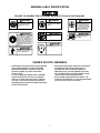
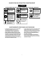
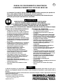
WARNING LABEL IDENTIFICATION
FAILURE TO OBSERVE THE FOLLOWING WARNINGS COULD RESULT IN INJURY.
Always wear eye protection
when operating or perform-
ing maintenance on this
tool.
WARNING
WARNING
Always wear hearing
protection when operating
this tool.
Always turn off the air sup-
ply and disconnect the air
supply hose before install-
ing, removing or adjusting
any accessory on this tool,
or before performing any
maintenance on this tool.
WARNING
Air powered tools can vibrate
in use. Vibration, repetitive
motions or uncomfortable po-
sitions may be harmful to your
hands and arms. Stop using
any tool if discomfort, tingling
feeling or pain occurs. Seek
medical advice before resum-
ing use.
WARNING
Do not carry the tool by
the hose.
WARNING
WARNING
Do not use damaged, frayed
or deteriorated air hoses
and fittings.
WARNING
Keep body stance balanced
and firm. Do not overreach
when operating this tool.
WARNING
Operate at 90 psig (6.2 bar/
620 kPa) Maximum air pressure.
90 psig
(6.2bar/620kPa)
SANDER SPECIFIC WARNINGS
• These Sanders will operate at the free speed specified
on the nameplate if the air supply line furnishes
90 psig (6.2 bar/620 kPa) air pressure at the tool.
Operation at higher air pressure will result in
excessive speed.
• Use only a sanding pad, buffing wheel or polishing
bonnet with these tools. Do not use any grinding
wheel, bur or metal removing accessory with these
tools. Never use an accessory having a maximum
operating speed less than the free speed of the Sander
in which it is being used.
• When using a pad having a shank, insert the shank to
full depth in the collet. When using a pad on a
threaded arbor, make certain the flange nut is
tightened securely. Check the tightness of the collet
nut or flange nut before operating a Sander to make
certain it will not loosen during operation.
• Do not attempt to disassemble the Controller. The
Controller is available only as a unit and is guaranteed
for the life of the tool if it is not abused.

3
PLACING TOOL IN SERVICE
LUBRICATION
Ingersoll–Rand No. 50
Always use an air line lubricator with these tools.
We recommend the following Filter–Lubricator–Regulator
Unit:
For USA – No. C31–06–G00
Before starting the tool, unless the air line lubricator is used,
detach the air hose and inject about 1.5 cc of oil into the air
inlet. For models with a built–in oiler, remove the Oil
Chamber Plug and fill the chamber.
After each eight hours of operation, or as experience
indicates, replenish the oil supply in the Handle.
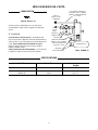
MAIN LINES 3 TIMES
AIR TOOL INLET SIZE
TO
AIR
SYSTEM
TO
AIR
TOOL
LUBRICATOR
REGULATOR
FILTER
BRANCH LINE 2 TIMES
AIR TOOL INLET SIZE
DRAIN REGULARLY
COMPRESSOR
(Dwg. TPD905–1)
HOW TO ORDER A SANDER
VERTICAL DISK WHEEL SANDER
Model Free Speed, rpm Spindle and Back Up Pad
99S45W109 4,500 5/8–11, 9”
99S60W107 6,000 5/8–11, 7”

Adressez toutes vos communications au Bureau
Ingersoll–Rand ou distributeur le plus proche.
Ingersoll–Rand Company 1999
Imprimé aux É.U.
MANUEL D’EXPLOITATION ET D’ENTRETIEN
DE LA SÉRIE 99S
NOTE
Les ponceuses verticales de la Série 99S sont destinées aux grosses opérations de ponçage
et de polissage où l’espace disponible est limité.
Ingersoll–Rand ne peut être tenu responsable de la modification des outils par le client pour
les adapter à des applications qui n’ont pas été approuvées par Ingersoll–Rand.
ATTENTION
D’IMPORTANTES INFORMATIONS DE SECURITÉ SONT JOINTES.
LIRE CE MANUEL AVANT D’UTILISER L’OUTIL.
L’EMPLOYEUR EST TENU DE COMMUNIQUER LES INFORMATIONS
DE CE MANUEL AUX EMPLOYÉS UTILISANT CET OUTIL.
LE NON RESPECT DES AVERTISSEMENTS SUIVANTS PEUT CAUSER DES BLESSURES.
MISE EN SERVICE DE L’OUTIL
• Toujours exploiter, inspecter et entretenir cet outil
conformément au Code de sécurité des outils
pneumatiques portatifs de l’American National
Standards Institute (ANSI B186.1).
• Pour la sécurité, les performances optimales et la
durabilité maximale des pièces, cet outil doit être
connecté à une alimentation d’air comprimé de
6,2 bar (620 kPa) maximum à l’entrée, avec un flexible
de 19 mm de diamètre intérieur.
• Couper toujours l’alimentation d’air comprimé et
débrancher le flexible d’alimentation avant d’installer,
déposer ou ajuster tout accessoire sur cet outil, ou
d’entreprendre une opération d’entretien quelconque
sur l’outil.
• Ne pas utiliser des flexibles ou des raccords
endommagés, effilochés ou détériorés.
• S’assurer que tous les flexibles et les raccords sont
correctement dimensionnés et bien serrés. Voir Plan
TPD905–1 pour un exemple type d’agencement des
tuyauteries.
• Utiliser toujours de l’air sec et propre à une pression
maximum de 6,2 bar. La poussière, les fumées
corrosives et/ou une humidité excessive peuvent
endommager le moteur d’un outil pneumatique.
• Ne jamais lubrifier les outils avec des liquides
inflammables ou volatiles tels que le kérosne, le gasol
ou le carburant d’aviation.
• Ne retirer aucune étiquette. Remplacer toute étiquette
endommagée.
UTILISATION DE L’OUTIL
• Porter toujours des lunettes de protection pendant
l’utilisation et l’entretien de cet outil.
• Porter toujours une protection acoustique pendant
l’utilisation de cet outil.
• Tenir les mains, les vêtements flous et les cheveux
longs, éloignés de l’extrémité rotative de l’outil.
• Prévoir, et ne pas oublier, que tout outil motorisé est
susceptible d’à–coups brusques lors de sa mise en
marche et pendant son utilisation.
• Garder une position équilibrée et ferme. Ne pas se
pencher trop en avant pendant l’utilisation de cet
outil. Des couples de réaction élevés peuvent se
produire à, ou en dessous, de la pression d’air
recommandée.
• Vérifier que la vitesse et les vibrations ne sont pas
excessives avant d’utiliser l’outil.
• La rotation des accessoires de l’outil peut continuer
pendant un certain temps après le relâchement de la
gâchette.
• Les outils pneumatiques peuvent vibrer pendant
l’exploitation. Les vibrations, les mouvements
répétitifs et les positions inconfortables peuvent causer
des douleurs dans les mains et les bras. N’utiliser plus
d’outils en cas d’inconfort, de picotements ou de
douleurs. Consulter un médecin avant de
recommencer à à utiliser l’outil.
• Utiliser les accessoires recommandés par
Ingersoll–Rand.
• Esta herramienta no ha sido diseñada para trabajar
en ambientes explosivos.
• Esta herramienta no está aislada contra descargas
eléctricas.
NOTE
L’utilisation de rechanges autres que les pièces d’origine Ingersoll–Rand peut causer des risques d’insécurité, réduire les
performances de l’outil et augmenter l’entretien, et peut annuler toutes les garanties.
Les réparations ne doivent être effectuées que par des réparateurs qualifiés autorisés. Consultez votre Centre de Service
Ingersoll–Rand le plus proche.
F

5
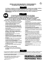
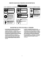
SIGNIFICATION DES ETIQUETTES D’AVERTISSEMENT
ATTENTION
LE NON RESPECT DES AVERTISSEMENTS SUIVANTS PEUT CAUSER DES BLESSURES
Porter toujours des lunettes
de protection pendant
l’utilisation et l’entretien de
cet outil.
ATTENTION ATTENTION
Porter toujours une
protection acoustique
pendant l’utilisation de cet
outil.
Les outils pneumatiques
peuvent vibrer pendant
l’exploitation. Les vibrations,
les mouvements répétitifs et les
positions inconfortables
peuvent causer des douleurs
dans les mains et les bras.
N’utiliser plus d’outils en cas
d’inconfort, de picotements ou
de douleurs. Consulter un
médecin avant de recommencer
à utiliser l’outil.
ATTENTION
Ne pas transporter l’outil
par son flexible.
ATTENTION
ATTENTION
Garder une position équilibrée et
ferme. Ne pas se pencher trop
en avant pendant
l’utilisation de cet outil.
ATTENTION
Utiliser de l’air comprimé
à une pression maximum
de 6,2 bar (620 kPa).
90 psig
(6.2bar/620kPa)
Couper toujours l’alimentation
d’air comprimé et débrancher le
flexible d’alimentation avant
d’installer, déposer ou ajuster
tout accessoire sur cet outil, ou
d’entreprendre une opération
d’entretien quelconque sur l’ou-
til.
ATTENTION
ATTENTION
Ne pas utiliser des flexibles ou
des raccords endommagés,
effilochés ou détériorés.
AVERTISSEMENTS SPÉCIFIQUES AUX PONCEUSES
• Ces ponceuses tourneront à la vitesse à vide spécifiée
sur la plaque signalétique lorsque le circuit
d’alimentation fournit de l’air à une pression de
6,2 bar (620 kPa) à l’outil. L’exploitation à une
pression supérieure produira une vitesse excessive.
• Utiliser seulement un plateau de ponçage, un disque
de polissage ou une peau de mouton de polissage avec
ces outils. Ne jamais utiliser de meule ou d’accessoire
d’ébavurage ou d’enlèvement de métal sur ces outils.
Ne jamais utiliser d’accessoire ayant une vitesse de
fonctionnement maximum inférieure à la vitesse à vide
de la ponceuse sur laquelle il est utilisé.
• Lorsqu’un plateau de ponçage à tige est utilisé, insérer
la tige à fond dans la pince. Lorsqu’un plateau est
utilisé sur un arbre fileté, vérifier que l’écrou de bride
est fermement serré. Vérifier le serrage de l’écrou de
pince ou de l’écrou d’arbre avant de mettre la
ponceuse en marche, et vérifier qu’il ne se desserre
pas pendant l’exploitation.
• Ne jamais essayer de démonter le contrôleur. Ce
dernier est fourni seulement comme un ensemble et
est garanti pendant toute la durée de vie de l’outil s’il
est utilisé correctement.

6
MISE EN SERVICE DE L’OUTIL
LUBRIFICATION
Ingersoll–Rand No. 50
Utiliser toujours un lubrificateur avec ces outils. Nous
recommandons l’emploi du filtre–régulateur–lubrificateur
suivant :
N
o
. C31–06–G00
Avant de mettre l’outil en marche, si un lubrificateur de
ligne n’est pas utilisé, débrancher le flexible d’alimentation et
verser environ 1,5 cm
3
d’huile dans le raccord d’admission de
l’outil. Sur les modèles dotés d’un huileur incorporé,
déposer le bouchon de l’huileur du corps du cylindre et
remplir la chambre d’huile.
Toutes les huit heures de fonctionnement, ou en fonction de
l’expérience, remplir la réserve d’huile de la poignée.
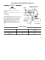
TUYAUTERIE PRINCIPALE
AU MOINS 3 FOIS LA DIMEN-
SION DE L’ADMISSION D’AIR
DE L’OUTIL
VERS LE
RÉSEAU D’AIR
COMPRIMÉ
VERS
L’OUTIL
PNEU-
MATIQUE
LUBRIFICATEUR
RÉGULATEUR
FILTRE
LIGNE SECONDAIRE AU
MOINS 2 FOIS LA DIMEN-
SION DE L’ADMISSION
D’AIR DE L’OUTIL
VIDANGER
RÉGULIÈREMENT
COMPRESSEUR
(Plan TPD905–1)
SPÉCIFICATIONS
Modèle Vitesse libre Broche et plateau
d’appui
tr/mn
99S45W109 4.500 5/8–11, 9”
99S60W107 6.000 5/8–11, 7”

Toda comunicación se deberá dirigir a la oficina o
al distribuidor Ingersoll–Rand más próximo.
Ingersoll–Rand Company 1999
Impreso en EE. UU.
MANUAL DE FUNCIONAMIENTO Y MANTENIMIENTO
LIJADORAS VERTICALES DE LA SERIE 99S
NOTA
Las lijadoras neúmaticas verticales de la serie 99S están diseñadas para trabajos de lijado y
pulido de alto rendimiento en aquellas situaciones en que el espacio es reducido.
Ingersoll–Rand no aceptará responsabilidad alguna por la modificación de las herramientas
efectuada por el cliente para las aplicaciones que no hayan sido consultadas con
Ingersoll–Rand.
AVISO
SE ADJUNTA INFORMACIÓN IMPORTANTE DE SEGURIDAD.
LEA ESTE MANUAL ANTES DE UTILIZAR LA HERRAMIENTA.
ES RESPONSABILIDAD DE LA EMPRESA ASEGURARSE DE QUE EL OPERARIO
ESTÉ AL TANTO DE LA INFORMACIÓN QUE CONTIENE ESTE MANUAL.
EL HACER CASO OMISO DE LOS AVISOS SIGUIENTES PODRÍA OCASIONAR LESIONES.
PARA PONER LA HERRAMIENTA EN SERVICIO
S Utilice, examine y mantenga siempre esta herramienta
conforme al código de seguridad para herramientas
neumáticas portátiles de la American National
Standards Institute (ANSI B186.1).
S Para mayor seguridad, rendimiento óptimo y larga
vida útil de las piezas, utilice esta herramienta a una
presión de aire máxima de 90 psig (6,2 bar/620 kPa)
con una manguera de suministro de aire con diámetro
interno de 19 mm.
S Corte siempre el suministro de aire y desconecte la
manguera de suministro de aire antes de instalar,
desmontar o ajustar cualquier accesorio de esta
herramienta, o antes de realizar cualquier operación
de mantenimiento de la misma.
S No utilice mangueras de aire y racores dañados,
desgastados o deteriorados.
S Asegúrese de que todos los racores y mangueras sean
del tamaño correcto y estén bien apretados. El Esq.
TPD905–1 muestra una disposición característica de
las tuberías.
S Use siempre aire limpio y seco a una presión máxima
de 90 psig (6,2 bar/620 kPa). El polvo, los gases
corrosivos y/o el exceso de humedad pueden estropear
el motor de una herramienta neumática.
S No lubrique las herramientas con líquidos inflamables
o volátiles tales como queroseno, gasoil o combustible
para motores a reacción.
S No saque ninguna etiqueta. Sustituya toda etiqueta
dañada.
UTILIZACIÓN DE LA HERRAMIENTA
• Use siempre protección ocular cuando utilice esta
herramienta o realice operaciones de mantenimiento
en la misma.
• Use siempre protección para los oídos cuando utilice
esta herramienta.
S Mantenga las manos, la ropa suelta y el cabello largo
alejados del extremo giratorio de la herramienta.
S Anticipe y esté alerta a los cambios repentinos en el
movimiento durante la puesta en marcha y utilización
de toda herramienta motorizada.
S Mantenga una postura del cuerpo equilibrada y firme.
No estire demasiado los brazos al manejar la
herramienta. Pueden darse elevados pares de reacción
a la presión de aire recomendada, e incluso a presiones
inferiores.
S Compruebe que no haya exceso de velocidad o
vibración de la herramienta antes de utilizarla.
S El eje de la herramienta puede seguir girando
brevemente después de haberse soltado la palanca de
mando.
S Las herramientas neumáticas pueden vibrar durante
el uso. La vibración, los movimientos repetitivos o las
posiciones incómodas pueden deñarle los brazos y
manos. En caso de incomodidad, sensación de
hormigueo o dolor, deje de usar la herramienta.
Consulte al médico antes de volver a utilizarla.
S Utilice únicamente los accesorios recomendados por
Ingersoll–Rand.
• Esta herramienta no ha sido diseñada para trabajar
en ambientes explosivos.
• Esta herramienta no está aislada contra descargas
eléctricas.
NOTA
El uso de piezas de recambio que no sean las auténticas piezas Ingersoll–Rand puede poner en peligro la seguridad, reducir el
rendimiento de la herramienta y aumentar los cuidados de mantenimiento necesarios, así como invalidar toda garantía.
Las reparaciones sólo se deben encomendar a personal debidamente cualificado y autorizado. Consulte con el centro de servicio
autorizado Ingersoll–Rand más próximo.
E

8
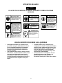
ETIQUETAS DE AVISO
AVISO
EL HACER CASO OMISO DE LOS AVISOS SIGUIENTES PODRÍA OCASIONAR
LESIONES.
Las herramientas neumáticas
pueden vibrar durante el uso.
La vibración, los movimientos
repetitivos o las posiciones
incómodas podrían dañarle los
brazos y las manos. En caso
de incomodidad, sensación de
hormigueo o dolor, dejar de
usar la herramienta. Consultar
al médico antes de volver a uti-
lizarla.
No coger la herramienta
por la manguera para le-
vantarla.
ADVERTENCIA
Mantener una postura del cuerpo
equilibrada y firme. No estirar de-
masiado los brazos al manejar la
herramienta.
Manejar la herramienta a una
presión de aire máxima de 90
psig (6,2 bar/620 kPa).
90 psig
(6.2bar/620kPa)
Cortar siempre el suministro
de aire y desconectar la man-
guera de suministro de aire
antes de instalar, retirar o ajus-
tar cualquier accesorio de esta
herramienta, o antes de realizar
cualquier operación de man-
tenimiento de la misma.
No utilizar mangueras de aire
y accesorios dañados, des-
gastados ni deteriorados.
ADVERTENCIA
ADVERTENCIA
ADVERTENCIA
ADVERTENCIA
ADVERTENCIA
ADVERTENCIA
ADVERTENCIA
Use siempre protección ocular
cuando utilice esta herramienta
o realice operaciones de
mantenimiento en la misma.
Use siempre protección para
los oídos cuando utilice esta
herramienta.
AVISOS ESPECÍFICOS SOBRE LAS LIJADORAS
S Estas lijadoras funcionan a la velocidad en vacío
que se indica en la placa de identificación si la red
de aire comprimido suministra a la herramienta
aire a una presión de 90 psig (6,2 bar/620 kPa).
El manejo a una presión superior producirá un
exceso de velocidad.
S Utilice solamente discos de lijar o de pulir con estas
herramientas. No utilice muelas de rectificar, fresas
ni accesorios de desbarbado de metal con estas
herramientas. No utilice nunca un accesorio cuya
velocidad máxima de funcionamiento sea inferior a
la velocidad en vacío de la lijadora con la que se
emplea.
S Al utilizar un disco con eje, introduzca el eje
completamente en la pinza. Cuando utilice un disco
en un eje roscado, asegúrese de que la tuerca de la
brida quede bien apretada. Compruebe el apriete
de la tuerca de la pinza o de la brida antes de
accionar la lijadora para asegurarse de que no se
afloje durante el funcionamiento.
S No intente desarmar el estrangulador. Éste está
disponible únicamente como conjunto y está
garantizado para toda la vida útil de la
herramienta, siempre que se utilice como es debido.

9
PARA PONER LA HERRAMIENTA EN SERVICIO
LUBRICACIÓN
Ingersoll–Rand Nº 50
Utilice siempre un lubricador de aire comprimido con estas
herramientas. Recomendamos utilizar el siguiente conjunto de
filtro–lubricador–regulador:
Para USA – Nº C31–06–G00
Antes de accionar la herramienta, salvo que se utilice un
lubricador de aire comprimido, desconecte la manguera de
aire e inyecte unos 1,5 cc de aceite en el conjunto de
admisión. Modelos con lubricador incorporado: saque el
tapón de la cámara de aceite de la carcasa del cilindro y llene
la cámara.
Después de cada ocho horas de funcionamiento, o según
indique la experiencia, reponga el nivel de aceite en la
empuñadura.
TUBERÍAS PRINCIPALES 3
VECES EL TAMAÑO DE
ENTRADA DE HERRAMIENTA
NEUMÁTICA
AL SISTEMA
NEUMÁTICO
A LA
HERRA–
MIENTA
NEUMÁTICA
LUBRICADOR
REGULADOR
FILTRO
TUBERÍA DE RAMAL
2 VECES EL TAMAÑO
DE ENTRADA DE
HERRAMIENTA
NEUMÁTICA
PURGAR
PERIÓDICAMENTE
COMPRESOR
(Esq. TPD905–1)
ESPECIFICACIONES
Modelo Velocidad en vacío Husillo y disco
soporte
rpm
99S45W109 4.500 5/8–11, 9”
99S60W107 6.000 5/8–11, 7”

Envie toda a correspondência ao Escritório
ou Distribuidor Ingersoll–Rand mais próximo.
Ingersoll–Rand Company 1999
Impresso nos E.U.A.
MANUAL DE FUNCIONAMENTO E MANUTENÇÃO
LIXADEIRAS PNEUMÁTICAS VERTICAIS SÉRIE 99S
AVISO
As Lixadeiras Pneumáticas Verticais Série 99S são concebidas para operações pesadas de
lixar e polir, onde as limitações de espaço são um factor relevante.
A Ingersoll–Rand não pode ser responsabilizada pela modificação de ferramentas para
aplicações para as quais não tenha sido consultada.
ADVERTÊNCIA
IMPORTANTES INFORMAÇÕES DE SEGURANÇA EM ANEXO.
LEIA ESTE MANUAL ANTES DE OPERAR A FERRAMENTA.
É RESPONSABILIDADE DA ENTIDADE PATRONAL PÔR AS INFORMAÇÕES
CONTIDAS NESTE MANUAL À DISPOSIÇÃO DOS UTILIZADORES.
A NÃO OBEDIÊNCIA ÀS ADVERTÊNCIAS SEGUINTES PODERÁ RESULTAR EM LESÕES PESSOAIS.
COLOCAÇÃO DA FERRAMENTA EM SERVIÇO
• Sempre opere, inspeccione e mantenha esta
ferramenta de acordo com o Código de Segurança
do Instituto Americano de Padrões Nacionais para
Ferramentas Pneumáticas Portáteis (ANSI B186.1).
• Para segurança, desempenho superior e
durabilidade máxima das peças, opere esta
ferramenta a uma pressão de ar máxima de 90 psig
(6,2 bar/620 kPa) na admissão com uma mangueira
de alimentação de ar com diâmetro interno de 3/4
pol. (19 mm).
• Desligue sempre a alimentação de ar e a mangueira
de alimentação de ar antes de instalar, retirar ou
ajustar qualquer acessório desta ferramenta, ou
antes de fazer manutenção na mesma.
• Não utilize mangueiras de ar e acessórios
danificados, puídos ou deteriorados.
• Certifique–se de que todas as mangueiras e
acessórios são da dimensão correcta e que estão
seguros firmemente. Consulte o Des. TPD905–1
para uma disposição de tubos típica.
• Utilize sempre ar limpo e seco a uma pressão
máxima de 90 psig. Poeira, fumos corrosivos e/ou
humidade excessiva podem destruir o motor de
uma ferramenta pneumática.
• Não lubrifique a ferramenta com líquidos
inflamáveis ou voláteis como querosene, gasóleo ou
combustível para jactos.
• Não retire nenhum rótulo. Substitua os rótulos
danificados.
UTILIZAÇÃO DA FERRAMENTA
• Use sempre protecção para os olhos ao operar ou
fazer manutenção nesta ferramenta.
• Use sempre protecção auricular ao operar esta
ferramenta.
• Mantenha as mãos, roupas soltas e cabelos longos
afastados da extremidade rotativa da ferramenta.
• Esteja preparado e alerta para mudanças súbitas no
movimento durante o arranque e o funcionamento
de qualquer ferramenta mecânica.
• Mantenha o corpo numa posição equilibrada e
firme. Não estique o corpo ao operar esta
ferramenta. Podem ocorrer binários de reacção
elevados à ou abaixo da pressão do ar
recomendada.
• Verifique a ferramenta quanto a velocidade ou
vibração excessiva antes de a operar.
• O veio da ferramenta pode continuar a rodar por
um curto período de tempo depois de soltar o
regulador.
• A ferramentas pneumáticas podem vibrar durante
a utilização. Vibração, movimentos repetitivos ou
posições desconfortáveis podem ser nocivos às suas
mãos e braços. Pare de utilizar qualquer
ferramenta se ocorrer desconforto, sensação de
formigueiro ou dor. Procure assistência médica
antes de reiniciar a utilização.
• Use os acessórios recomendados pela
Ingersoll–Rand.
• Esta ferramenta não é concebida para funcionar em
atmosferas explosivas.
• Esta ferramenta não é isolada contra choque
eléctrico.
AVISO
A utilização de qualquer peça sobresselente que não seja Ingersoll–Rand genuína pode resultar em riscos para a
segurança, em desempenho reduzido da ferramenta e mais necessidade de manutenção, e pode invalidar todas as
garantias.
As reparações só devem ser feitas por pessoal autorizado e com formação adequada. Consulte o Representante Autorizado
Ingersoll–Rand mais próximo.
P

11
IDENTIFICAÇÃO DAS ETIQUETAS DE ADVERTÊNCIA
ADVERTÊNCIA
A NÃO OBEDIÊNCIA ÀS ADVERTÊNCIAS SEGUINTES PODERÁ RESULTAR EM LESÕES PESSOAIS.
Use sempre protecção para os
olhos ao operar ou fazer
manutenção nesta ferramenta.
Use sempre protecção
auricular ao operar esta
ferramenta.
Desligue sempre a alimentação
de ar e a mangueira de
alimentação de ar antes de
instalar, remover ou ajustar um
acessório desta ferramenta, ou
antes de fazer manutenção na
mesma.
As ferramentas pneumáticas
podem vibrar durante a utilização.
Vibração, movimentos repetitivos
ou posições desconfortáveis
podem ser nocivos às suas mãos e
braços. Pare de utilizar qualquer
ferramenta se ocorrer desconforto,
sensação de formigueiro ou dor.
Procure assistência médica antes
de reiniciar a utilização.
Não transporte a ferramenta
pela mangueira.
ADVERTÊNCIA
Não utilize mangueiras de
ar e acessórios danificados,
puídos ou deteriorados.
Mantenha o corpo numa
posição equilibrada e firme.
Não estique o corpo ao
operar esta ferramenta.
Opere a uma pressão de ar
máxima de 90 psig (6,2 bar/
620 kPa).
90 psig
(6.2bar/620kPa)
ADVERTÊNCIA
ADVERTÊNCIA
ADVERTÊNCIA
ADVERTÊNCIA
ADVERTÊNCIA
ADVERTÊNCIA
ADVERTÊNCIA
ADVERTÊNCIAS ESPECIAIS PARA A LIXADEIRA
• Estas Lixadeiras funcionarão à velocidade livre
especificada na placa de identificação se a linha de
ar fornecer pressão de ar a 90 psig (6,2 bar/
620 kPa) na ferramenta. A operação a uma pressão
mais elevada resultará em velocidade excessiva.
• Utilize apenas uma almofada de lixar, roda de polir
ou boina de polir com estas ferramentas. Não utilize
mó abrasiva, rebarbador ou acessório para
remoção de metal com estas ferramentas. Nunca
utilize um acessório que tenha uma velocidade
máxima de funcionamento abaixo da velocidade
livre da Lixadeira na qual o acessório está a ser
utilizado.
• Ao utilizar uma almofada que tenha um veio,
introduza–o totalmente no mandril. Ao utilizar uma
almofada num veio roscado, certifique–se de que a
porca de flange está apertada firmemente. Verifique
o aperto da porca do mandril ou da porca de flange
antes de operar a Lixadeira para assegurar que a
porca não desapertará durante o funcionamento.
• Não tente desmontar o Controlador. O Controlador
só está disponível como uma unidade e é garantido
durante a vida útil da ferramenta, se não for
maltratado.

12
COLOCAÇÃO DA FERRAMENTA EM SERVIÇO
LUBRIFICAÇÃO
Ingersoll–Rand Nº 50
Utilize sempre um lubrificador de linha de ar com estas
ferramentas.
Recomendamos a seguinte Unidade Filtro–Lubrificador–
Regulador:
Nº. C31–06–G00
Antes de ligar a ferramenta, a menos que o lubrificador de
linha de ar esteja a ser utilizado, desligue a mangueira de ar e
injecte aproximadamente 1,5 cc de óleo na admissão de ar.
Para modelos com lubrificador incorporado, remova o
bujão de óleo da câmara da caixa do cilindro e encha a
câmara.
Após cada oito horas de funcionamento, ou conforme a
experiência indicar, complete o abastecimento de óleo na
Pega.
LINHAS PRINCIPAIS – 3 VEZES
A DIMENSÃO DA ADMISSÃO DA
FERRAMENTA PNEUMÁTICA
PARA O
SISTEMA
DE AR
PARA A
FERRAMENTA
PNEUMÁTICA
LUBRIFICADOR
REGULADOR
FILTRO
LINHA SECUNDÁRIA –
2 VEZES A DIMENSÃO
DA ADMISSÃO DA
FERRAMENTA
PNEUMÁTICA
DRENAR
REGULARMENTE
COMPRESSOR
(Des. TPD905–1)
ESPECIFICAÇÕES
Modelo Velocidade Livre Haste e Almofada
de Apoio
rpm mm (pol.)
99S45W109 4.500 5/8–11, 9”
99S60W107 6.000 5/8–11, 7”

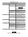
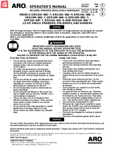
MAINTENANCE SECTION
13
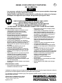
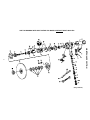
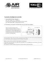
USE THIS DRAWING WITH PART LISTING FOR MODELS WITHOUT BUILT–IN OILERS
(Dwg. TPA1709)

MAINTENANCE SECTION
14
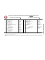
USE THIS PART LISTING WITH DRAWING TPA1709 FOR MODELS WITHOUT BUILT–IN OILERS
PART NUMBER FOR ORDERING PART NUMBER FOR ORDERING
+ 1
Cylinder Case Assembly . . . . . . . . . . . . . . . . .
99V60–EU–A25A 18A Exhaust Diffuser (not used on
2
Throttle Valve Assembly . . . . . . . . . . . . . .
88V60–A302 99S45 or 99S60) . . . . . . . . . . . . . . . . . . . . . . . 99V77–123
3 Throttle Seal (2) . . . . . . . . . . . . . . . . . . . . . . C321–606 19
Exhaust Deflector . . . . . . . . . . . . . . . . . . .
99V60–23
5
Inlet Bushing . . . . . . . . . . . . . . . . . . . . . .
88V60–38 20
Exhaust Deflector Screw (3) . . . . . . . . . . . .
99V60–200
• 5A
Inlet Bushing Screen . . . . . . . . . . . . . . . . .
834–61 *
Nameplate Kit . . . . . . . . . . . . . . . . . . . . .
99V–K301A
• 6
Throttle Valve Spring . . . . . . . . . . . . . . . .
99V60–262
Nameplate Screw (4) . . . . . . . . . . . . . . .
BN403–302
7
Throttle Valve Seat Support Assembly . . . . .
88V60–A303
Warning Label . . . . . . . . . . . . . . . . . . .
WARNING–4–99
• 8
Air Strainer Screen . . . . . . . . . . . . . . . .
834–61 27
Dead Handle
. . . . . . . . . . . . . . . . . . . . . . . . .
ERG0–A48
• 10
Valve Seat . . . . . . . . . . . . . . . . . . . . . .
R4–159A 29 Arbor
11
Valve Seat Washer . . . . . . . . . . . . . . . .
99V60–155
for 99S45 (Orange) . . . . . . . . . . .
99S45–204–W10
12
Valve Seat Lock Washer . . . . . . . . . . . .
H54U–352
for 99S60 (Blue) . . . . . . . . . . . . .
99S60–204–W10
13
Valve Seat Screw . . . . . . . . . . . . . . . . .
PS3–83 30
Front Rotor Bearing . . . . . . . . . . . . . . . . . . . .
R380–105
14
Throttle Lever Pin . . . . . . . . . . . . . . . . . .
MR–100 31
Front End Plate . . . . . . . . . . . . . . . . . . . . . . .
99V60–11
15
Locking Lever Assembly . . . . . . . . . . . . . .
88V60–A400
16
Lever Lock . . . . . . . . . . . . . . . . . . . . .
88V60–402
17
Lever Lock Spring . . . . . . . . . . . . . . . .
88V60–405
18
Lever Lock Pin . . . . . . . . . . . . . . . . . .
502B–120
* Not illustrated.
• To keep downtime to a minimum, it is desirable to have on hand certain repair parts. We recommend that you stock one (pair or set) of each part indicated
by a bullet (•) for every four tools in service.
+ Whenever a new Cylinder Case Assembly is installed, select the correct Nameplate from the Nameplate Kit and attach it to the Cylinder case with the Nameplate .
Screws.

MAINTENANCE SECTION
15
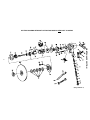
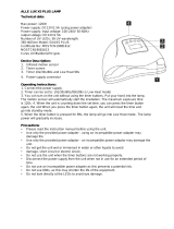
USE THIS DRAWING WITH PART LISTING FOR MODELS WITH BUILT–IN OILERS
(Dwg. TPA1574–1)

MAINTENANCE SECTION
16
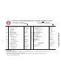
USE THIS PART LISTING WITH DRAWING TPA1574–1 FOR MODELS WITH BUILT–IN OILERS
PART NUMBER FOR ORDERING
PART NUMBER FOR ORDERING
+ 1
Cylinder Case Assembly . . . . . . . . . . . . . .
––––– 19
Exhaust Deflector . . . . . . . . . . . . . . . . .
99V60–23
2
Throttle Valve Assembly . . . . . . . . . . . .
99V60–A302 20
Exhaust Deflector Screw (3) . . . . . . . . . .
99V60–200
♦ 3
Small Seal . . . . . . . . . . . . . . . . . . . .
AFH120A–358 * Nameplate Kit . . . . . . . . . . . . . . . . . . . . . . . 99V–K301
♦ 4
Large Seal . . . . . . . . . . . . . . . . . . . .
C321–606
Nameplate Screw (4) . . . . . . . . . . . . .
BN403–302
5
Inlet Bushing . . . . . . . . . . . . . . . . . . . .
88V60–38
Warning Label . . . . . . . . . . . . . . . . .
WARNING–5–99
♦• 5A
Inlet Bushing Screen . . . . . . . . . . . . . . .
834–61 ♦ 21
Oiler Chamber Plug Washer . . . . . . . . . . . .
R3–92A
• 6
Throttle Valve Spring . . . . . . . . . . . . . .
99V60–262 22
Oiler Chamber Plug . . . . . . . . . . . . . . . . .
231–665
7 Throttle Valve Seat Support 23
Oiler Assembly . . . . . . . . . . . . . . . . . . . .
99V60–A198
Assembly . . . . . . . . . . . . . . . . . . . . . . . . . . . 99V60–A303 ♦ 24
Oiler Felt (2) . . . . . . . . . . . . . . . . . . . .
R1–75
♦• 8
Air Strainer Screen . . . . . . . . . . . . . .
99V60–61 25
Oiler Adjusting Screw . . . . . . . . . . . . . .
R1–71A
9
Valve Seat Cap . . . . . . . . . . . . . . . . .
R4–157 ♦ 26
Oiler Body Seal . . . . . . . . . . . . . . . . . .
HRA20A–117
♦• 10
Valve Seat . . . . . . . . . . . . . . . . . . . .
R4–159A 27
Dead Handle . . . . . . . . . . . . . . . . . . . . . .
99V60–48
11
Valve Seat Washer . . . . . . . . . . . . . .
99V60–155 28
Dead Handle Screw . . . . . . . . . . . . . . . . .
99V60–634
12 Valve Seat Lock Washer . . . . . . . . . . . . H54U–352 29 Arbor
13
Valve Seat Screw . . . . . . . . . . . . . . .
99V60–83
for 99S45 (Orange) . . . . . . . . .
99S45–204–W10
• 14
Throttle Lever Pin . . . . . . . . . . . . . . . .
MR–100
for 99S60 (Blue) . . . . . . . . . . .
99S60–204–W10
15
Locking Lever Assembly . . . . . . . . . . . .
99V60–A400A 30 Front Rotor Bearing . . . . . . . . . . . . . . . . . . . . . R380–105
16
Lever Lock . . . . . . . . . . . . . . . . . . .
88V60–402 31
Front End Plate . . . . . . . . . . . . . . . . . . . .
99V60–11
17
Lever Lock Spring . . . . . . . . . . . . . .
88V60–405
18
Lever Lock Pin . . . . . . . . . . . . . . . .
502B–120
* Not illustrated.
♦ Indicates Tune–up Kit part.
• To keep downtime to a minimum, it is desirable to have on hand certain repair parts. We recommend that you stock one (pair or set) of each
part indicated by a bullet (•) for every four tools in service.
+ Whenever a new Cylinder Case Assembly is installed, select the correct Nameplate from the Nameplate Kit and attach it to the
Cylinder case with the Nameplate Screws.

MAINTENANCE SECTION
17
USE THIS PART LISTING FOR ALL MODELS
PART NUMBER FOR ORDERING PART NUMBER FOR ORDERING
• 33
Rotor Key . . . . . . . . . . . . . . . . . . . . . . . . .
R43F–70 55 Arbor Wrench (double end 5/8” x 3/4”) . . . . . . . DG120–69
34
Rotor . . . . . . . . . . . . . . . . . . . . . . . . . . . .
99V60–53 56 Adjustable Spanner Wrench . . . . . . . . . . . . . . . . AG230–26M
♦• 35
Vane Packet (set of 4 Vanes) . . . . . . . . . . . . .
99V60–42–4 *
Piped–Away Exhaust Kit . . . . . . . . . . . . . . .
99V60–K184
36
Cylinder Assembly . . . . . . . . . . . . . . . . . . .
99V60–A3
Exhaust Hose . . . . . . . . . . . . . . . . . . . . .
99V60–184
37
End Plate Dowel . . . . . . . . . . . . . . . . . . .
5040–6
Exhaust Hose Clamp . . . . . . . . . . . . . . . .
DG30–67
38
Cylinder Dowel . . . . . . . . . . . . . . . . . . .
502B–120
Exhaust Elbow . . . . . . . . . . . . . . . . . . . .
99V60–167
39
Exhaust Silencer . . . . . . . . . . . . . . . . . . . . .
99V60–311
Exhaust ElbowGasket . . . . . . . . . . . . . . .
99V60–49
40 Rear End Plate . . . . . . . . . . . . . . . . . . . . . . . . . . . 99V60–A12
Exhaust Elbow Screw (3) . . . . . . . . . . . . .
FEA100–112
♦• 41
Rear End Plate Gasket
. . . . . . . . . . . . . . . . .
99V60–739
Exhaust Hose Band (4) . . . . . . . . . . . . . .
99V60–927
42 Controller Assembly (consists of
Exhaust Hose Band Screw (4) . . . . . . . . . .
MT1–36–7/8
Controller and Rotor Bearing Seal Assembly)
Nut (6) . . . . . . . . . . . . . . . . . . . . . . . . .
G8–120A
for 99S45 (4500 rpm) (Orange) . . . . . 99V45–A524
Screw (2) . . . . . . . . . . . . . . . . . . . . . . .
JC3350–103
for 99S60 (6000 rpm) (Blue) . . . . . . . 99V60–A524 * Tune–up Kit (for models with built–in oiler)
43 Rotor Bearing Seal Assembly (consists of Rear (includes illustrated parts 3, 4 [2], 5A [2], 8,
Rotor Bearing and Rotor Bearing Seal) . . . . 99V60–A28A 10, 21, 24 [2], 26, 35, 41 and 48) . . . . . . . . . . . . 99V/99H–TK3
45
Rotor Bearing Cage . . . . . . . . . . . . . . . . . .
99V60–107A *
Exhaust Deflector Screw Wrench (1/8” hex) . .
R2J–562
46 Controller Retaining Nut *
Maintenance Tool Kit . . . . . . . . . . . . . . . . .
99V60–K950
for 99S45 . . . . . . . . . . . . . . . . .
R4–120
Controller Wrench . . . . . . . . . . . . . . . . .
99V60–950
for 99S60 . . . . . . . . . . . . . . . . . .
G8–120A
Seal Pressing Tool . . . . . . . . . . . . . . . . .
99V60–951
47
Motor Clamp Belleville Washer (2) . . . . . . . .
99V60–207
Bearing Clamp . . . . . . . . . . . . . . . . . . . .
99V60–A952
♦• 48
Cylinder Case Gasket . . . . . . . . . . . . . . . . .
99V60–283 *
Wheel Retaining Screw Wrench (5/32” hex) . .
88V–562
49 Motor Retaining Plate . . . . . . . . . . . . . . . . . . . . . 99S60–55
50 Pad Mounting Kit . . . . . . . . . . . . . . . . . . . . . . . . 77A–826
51
Cylinder Case Screw Lock Washer (4) . . . . . .
10BM–67
52
Cylinder Case Screw (4) . . . . . . . . . . . . . . .
99V60–638
53 Sanding Pad Assembly
with 5” Sanding Pad . . . . . . . . . . . . . 77A–AM825–5
with 7” Sanding Pad (medium) . . . . . 77A–AM825–7
with 7” Sanding Pad (firm) . . . . . . . . 77A–BM825–7
with 9” Sanding Pad . . . . . . . . . . . . . 77A–AM825–9
* Not illustrated.
♦ Indicates Tune–up Kit part.
• To keep downtime to a minimum, it is desirable to have on hand certain repair parts. We recommend that you stock one (pair or set) of each
part indicated by a bullet (•) for every four tools in service.

18
MAINTENANCE SECTION
Always wear eye protection when operating or per-
forming maintenance on this tool.
Always turn off the air supply and disconnect the air
supply hose before installing, removing or adjusting
any accessory on this tool, or before performing any
maintenance on this tool.
LUBRICATION
Each time a Series 99S Vertical Air Sander is disas-
sembled for maintenance and repair or replacement of
parts, lubricate the tool as follows:
1. Inject approximately 1.5 cc of Ingersoll–Rand No. 50
Oil into the Inlet Bushing (5) after assembly. For
models with a built–in oiler, fill the chamber of the
Oiler Assembly (23). After each eight hours of op-
eration, replenish the oil supply.
2. If the Sander is used in an extremely dirty environ-
ment, once each week or after each forty hours of
operation, pour a liberal amount of a clean, suitable
cleaning solution into the slots in the handle. Work
the throttle lever vigorously to wash the cleaning
solution around, and then pour the solution and accu-
mulated dirt from the handle. Repeat this process
until the cleaning solution is clean when it comes out
of the handle. Immediately after flushing with the
cleaning solution, inject a liberal amount of Inger-
soll–Rand No. 50 Oil in the slots and again work the
throttle lever vigorously to lubricate the cleaned
parts.
OILER ADJUSTMENT
(for models with built–in oiler)
The built–in lubricator has been properly adjusted at the
factory. If the oiler felts are clogged and must be replaced,
proceed as follows:
1. Remove the Sanding Pad Assembly (53). Remove the
Cylinder Case Screws (52), the Lock Washers (51),
the Cylinder Case Gasket (48), the two Motor Clamp
Washers (47) and the Motor Retaining Plate (49).
2. With a thin blade screwdriver, remove the Oiler Ad-
justing Screw (25) from the Oiler Assembly (23).
3. Using tweezers or a piece of bent wire, remove the
Oiler Felts (24) and install new ones.
4. Replace the Oiler Adjusting Screw, installing it
slightly below flush.
DISASSEMBLY
General Instructions
1. Do not disassemble the tool any further than neces-
sary to replace or repair damaged parts.
2. Whenever grasping a tool or a part in a vise, always
use leather–covered or copper–covered vise jaws to
protect the surface of the part and help prevent distor-
tion. This is particularly true of threaded members
and housings.
3. Do not remove any part which is a press fit in or on a
subassembly unless the removal of that part is neces-
sary for repairs or replacement.
4. Do not disassemble the tool unless you have a com-
plete set of new gaskets and O–rings for replace-
ments.
Disassembly of the Motor
1. Lightly grasp the live air handle of the Sander in
leather–covered or copper–covered vise jaws, Sand-
ing Pad Assembly (53) up.
2. Remove the Sanding Pad Assembly, Cylinder Case
Screws (52), the Lock Washers (51), the Cylinder
Case Gasket (48), the two Motor Clamp Washers (47)
and the Motor Retaining Plate (49).
3. Grasp the Arbor (29) in the vise and lift the Cylinder
Case to expose the motor.
4. Remove the Exhaust Silencer (39).
5. For models with a built–in oiler, take the tool from
the vise and dump the oil from its reservoir. The Oil-
er Assembly (23) can be pulled from the Cylinder
Case, if necessary.
Use only the special No. 99V60–950 Controller
Wrench for removing the Controller Assembly.
Do not attempt to disassemble the Controller. It is
available only as a unit and is guaranteed for the
life of the tool if it is not abused.
The Controller Assembly (42) has a left–hand
thread and the Controller Nut (46) has a right–
hand thread.
6. Remove the Controller Nut and unscrew the Control-
ler Assembly (42).
7. Lift off the Rear End Plate (40) and Rotor Bearing
Seal.
8. Lift off the Cylinder (36).
9. Remove the Vanes (35).
10. Withdraw the Rotor (34) followed by the Rotor Key
(33).
11. Lift off the Front End Plate (31).
12. If the Front Rotor Bearing (30) is to be replaced,
press it and the Arbor from the Front End Plate.
Press off the Bearing from the Arbor.

19
MAINTENANCE SECTION
13. Set the Controller on blocks in an arbor press. Using
a round piece of metal fitting the inner race of the
Rear Rotor Bearing, press off the Rear Rotor Bearing
Cage (45).
14. Insert the Controller into the 99V60–A952 Bearing
Clamp and tighten the nut on the fixture. Insert the
99V60–A951 Seal Pressing Tool in the center and
press off the Controller. Release the clamp.
Disassembly of the Throttle and Inlet for Models
without a built–in oiler
1. Place the Cylinder Case in the vise to remove the
Inlet Bushing (5), Inlet Bushing Screen (5A) and the
Throttle Valve Spring (6). The Bushing has an inter-
ference thread and is tightly fit.
2. Drive out the Throttle Lever Pin (14) to release the
Lever Assembly (15).
3. Using a 3/32” hex wrench, reach inside the handle
and remove the Valve Seat Screw (13) from the
Throttle Valve Seat Support Assembly (7).
4. Thread a No. 8–32 screw about 5” (127 mm) long
into the throttle valve seat support in place of the re-
moved valve seat screw. A piece of 5/32” welding
rod can be threaded on one end to serve the same pur-
pose.
5. Grasp the protruding end of the screw in a vise, and
while tapping lightly on the housing or handle with a
plastic hammer, pull on the housing or handle to
withdraw the throttle parts.
6. The Air Strainer Screen (8) can now be removed and
cleaned.
Disassembly of the Throttle and Inlet for Models
with a built–in oiler
1. Place the Cylinder Case in the vise to remove the
Inlet Bushing (5) and Inlet Bushing Screen (5A).
2. Drive out the Throttle Lever Pin (14) to release the
Lever Assembly (15).
3. Remove the Throttle Valve Spring (6) and release the
Throttle Valve (2) by tapping the end of the handle
with a soft hammer.
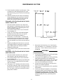
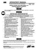
4. Bend a piece of 1/8” diameter rod as shown in Draw-
ing TPD548. Insert this “puller” into the screw head
and withdraw the Throttle Valve Seat Support Assem-
bly (7) by hand, or with lever–wrench pliers, using a
prying action if needed.
1/8” DIAMETER (3 mm) ROD
(Dwg. TPD548)
5. Remove the Valve Seat Screw (13), Valve Seat (10),
Valve Seat Washer (11), Lock Washer (12) and Valve
Seat Cap (9). The Air Strainer Screen (8) may now
be removed.
ASSEMBLY
General Instructions
1. Always press on the inner ring of a ball–type bearing
when installing the bearing on a shaft.
2. Always press on the outer ring of a ball–type bearing
when pressing the bearing into a bearing recess.
3. Whenever grasping a tool or part in a vise, always use
leather–covered or copper–covered vise jaws. Take
extra care with threaded parts or housings.
4. Always clean every part and wipe every part with a
thin film of oil before installation.
5. Apply a film of O–ring lubricant to all O–rings before
final assembly.
6. Check every bearing for roughness. If an open bear-
ing must be cleaned, wash it thoroughly in a suitable
cleaning solution and dry with a clean cloth. Sealed
or shielded bearing should never be cleaned. Work
grease thoroughly into every open bearing before
installation.

20
MAINTENANCE SECTION
Assembly of the Throttle and Inlet
Thoroughly clean and lubricate all Throttle Valve
components before assembling the tool. Lubricate
with Ingersoll–Rand Light Oil No. 10.
1. Grasp the live air handle in leather–covered or cop-
per–covered vise jaws with the live air handle open-
ing upward.
2. Assemble the Valve Seat Support parts.
3. Insert the Support Assembly (7) into the handle, large
diameter first. Locate a punch on the flat of the
screw head and tap it with a hammer until the Assem-
bly is firmly seated.
4. Apply O–ring lubricant to the Seals (3) or (3 and 4).
Fit the seals to the Throttle Valve (2) and push the
assembly, small diameter first, into the handle until it
seats firmly.
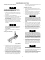
If Lever Assembly being serviced does not have
the window–type lever, install a complete new
Lever Assembly.
5. Assemble the Lever Assembly (15) as illustrated
below.
Locking Lever Assembly
(Dwg. TPD563)
6. Align the holes in the Lever Assembly with the slots
in the Cylinder Case. With a soft face hammer, tap
the Throttle Lever Pin (14) through the Lever Assem-
bly. File off any sharp edges. Operate the mechanism
internally by hand to assure operation.
7. Insert the Throttle Valve Spring (6), small end first.
8. Clean the face of the Inlet Bushing (5) and the Inlet
Bushing Screen (5A) using a suitable cleaning solu-
tion, and dry them. Insert the screen and bushing in
the end of the Cylinder Case by grasping the flats
with a wrench. Tighten the Bushing between 35 and
45 ft–lb. (47 and 61 Nm) torque.
Assembly of the Motor
1. Using an arbor press against the inner race of the
bearing, install the Front Rotor Bearing (30) onto the
Arbor (29).
2. Inspect the Front End Plate (31) for nicks or burrs.
Press the arbor bearing into the front end plate.
3. With the Arbor held firmly in vise jaws, place the
Rotor Key (33) in the slot of the Rotor (34).
The Rotor should slip fit over the Arbor. If tight-
ness is detected, lightly polish one long side of the
Key using fine emery cloth on a hard, flat surface.
Replace the Key with the polished side toward the
Arbor.
4. The Rotor is counter–bored on one end. Place that
end over the Arbor. Apply a light film of Ingersoll–
Rand No. 50 Oil to each Vane (35) and insert one
vane, straight end out, into each slot in the Rotor. If
any new Vanes are required, replace the entire set.
5. Place the Cylinder Assembly (36) over the Rotor
matching the End Plate Dowel (short dowel) (37) to
the alignment hole in the Front End Plate (31).
If the Controller Assembly (42) needs to be re-
placed, you must also replace the Rotor Bearing
Seal Assembly (43) which consists of the Rear Ro-
tor Bearing and Rotor Bearing Seal. If either the
Rear Rotor Bearing or Rotor Bearing Seal needs
to be replaced, both must be replaced with a new
Bearing and Seal. Do not mix old and new parts.
6. Clean the Rotor Bearing Seal (43) and measure the
outside diameter and large inside diameter. If the
outside diameter is worn to 1.1764” (29.88/mm) or
smaller, and/or the large inside diameter is worn to
0.9103: (23.122 mm) or larger, install a new Rotor
Bearing Seal.
Take all measurements 90 degrees to the left of the
dowel hole when facing the hub side of the Seal.
7. Align the Rear End Plate (40), cavity and pin up, with
the larger hole in the Rotor Bearing Seal.
8. Press the Rear Rotor Bearing onto the Controller As-
sembly (42). Press the Controller Assembly into the
Bearing Cage (45) to within 1/8” of seating.
Page is loading ...
Page is loading ...
Page is loading ...
-
 1
1
-
 2
2
-
 3
3
-
 4
4
-
 5
5
-
 6
6
-
 7
7
-
 8
8
-
 9
9
-
 10
10
-
 11
11
-
 12
12
-
 13
13
-
 14
14
-
 15
15
-
 16
16
-
 17
17
-
 18
18
-
 19
19
-
 20
20
-
 21
21
-
 22
22
-
 23
23


Ingersoll-Rand 99S Operation and Maintenance Manual
- Type
- Operation and Maintenance Manual
Ask a question and I''ll find the answer in the document
Finding information in a document is now easier with AI
in other languages
- español: Ingersoll-Rand 99S
Related papers
-
Ingersoll-Rand 88S Operation and Maintenance Manual
-
Ingersoll-Rand 88V60S106M Operation and Maintenance Manual
-
-
-
Ingersoll-Rand 99V Series Maintenance Information
-
 Casera TR-06Q User manual
-
-
-
-

Other documents
-
Husky H4870 Operating instructions
-
-
Ingersoll Rand 244A User manual
-
 ATD Tools Sander ATD-2088 User manual
-
 Toku 430101V0J Operating instructions
-
 Sidchrome SCMTTA-050C User manual
-
MAC TOOLS AWB538A User manual
-
 ALLE LUX X5 Plus Operating instructions
-
Ericsson R380 User manual
-
 ARO RS25A–VLK User manual


