Page is loading ...

Refer All Communications to the Nearest
Ingersoll–Rand Office or Distributor.
Ingersoll–Rand Company 1998
Printed in U.S.A.
04575775
Form P7351
Edition 1
OPERATION AND MAINTENANCE MANUAL
FOR
MODEL DG600G2 AIR PENCIL GRINDERS
Model DG600G2 Pencil Grinders are designed for precision grinding in confined areas.
Ingersoll–Rand is not responsible for customer modification of tools for applications on
which Ingersoll–Rand was not consulted.
IMPORTANT SAFETY INFORMATION ENCLOSED.
READ THIS MANUAL BEFORE OPERATING TOOL.
IT IS THE RESPONSIBILITY OF THE EMPLOYER TO PLACE THE INFORMATION
IN THIS MANUAL INTO THE HANDS OF THE OPERATOR.
FAILURE TO OBSERVE THE FOLLOWING WARNINGS COULD RESULT IN INJURY.
PLACING TOOL IN SERVICE
• Always operate, inspect and maintain this tool in
accordance with American National Standards
Institute Safety Code for Portable Air Tools
(ANSI B186.1).
• For safety, top performance, and maximum
durability of parts, operate this tool at 90 psig
(6.2 bar/620 kPa) maximum air pressure at the inlet
with 7/32” (6 mm) inside diameter air supply hose.
• Always turn off the air supply and disconnect the
air supply hose before installing, removing or
adjusting any accessory on this tool, or before
performing any maintenance on this tool.
• Do not use damaged, frayed or deteriorated air
hoses and fittings.
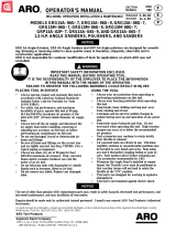
• Be sure all hoses and fittings are the correct size
and are tightly secured. See Dwg. TPD905–1 for a
typical piping arrangement.
• Always use clean, dry air at 90 psig maximum air
pressure. Dust, corrosive fumes and/or excessive
moisture can ruin the motor of an air tool.
• Do not lubricate tools with flammable or volatile
liquids such as kerosene, diesel or jet fuel.
• Do not remove any labels. Replace any damaged
label.
USING THE TOOL
• Always wear eye protection when operating or
performing maintenance on this tool.
• Always wear hearing protection when operating
this tool.
• Keep hands, loose clothing and long hair away from
rotating end of tool.
• Anticipate and be alert for sudden changes in
motion during start up and operation of any power
tool.
• Keep body stance balanced and firm. Do not
overreach when operating this tool. High reaction
torques can occur at or below the recommended air
pressure.
• Tool accessories may continue to rotate briefly after
throttle is released.
• Air powered tools can vibrate in use. Vibration,
repetitive motions or uncomfortable positions may
be harmful to your hands and arms. Stop using any
tool if discomfort, tingling feeling or pain occurs.
Seek medical advice before resuming use.
• Use accessories recommended by Ingersoll–Rand.
• This tool is not designed for working in explosive
atmospheres.
• This tool is not insulated against electric shock.
The use of other than genuine Ingersoll–Rand replacement parts may result in safety hazards, decreased tool
performance, and increased maintenance, and may invalidate all warranties.
Repairs should be made only by authorized trained personnel. Consult your nearest Ingersoll–Rand Authorized
Servicenter.
F
E
P

2
WARNING LABEL IDENTIFICATION
FAILURE TO OBSERVE THE FOLLOWING WARNINGS COULD RESULT IN INJURY.
Always wear eye protection
when operating or perform-
ing maintenance on this
tool.
WARNING
WARNING
Always wear hearing
protection when operating
this tool.
Always turn off the air sup-
ply and disconnect the air
supply hose before install-
ing, removing or adjusting
any accessory on this tool,
or before performing any
maintenance on this tool.
WARNING
Air powered tools can vibrate
in use. Vibration, repetitive
motions or uncomfortable po-
sitions may be harmful to your
hands and arms. Stop using
any tool if discomfort, tingling
feeling or pain occurs. Seek
medical advice before resum-
ing use.
WARNING
Do not carry the tool by
the hose.
WARNING
WARNING
Do not use damaged, frayed
or deteriorated air hoses
and fittings.
WARNING
Keep body stance balanced
and firm. Do not overreach
when operating this tool.
WARNING
Operate at 90 psig (6.2 bar/
620 kPa) Maximum air pressure.
90 psig
(6.2bar/620kPa)
GRINDER SPECIFIC WARNINGS
• Do not use this tool if the actual free speed exceeds
the nameplate rpm.
• Before mounting a wheel, after all tool repairs and
whenever a Grinder is issued for use, check the free
speed of the Grinder with a tachometer to make
certain its actual speed at 90 psig (6.2 bar/620 kPa)
does not exceed the rpm stamped or printed on the
nameplate. Grinders in use on the job must be
similarly checked at least once each shift.
• Make certain the grinding wheel properly fits the
arbor. The wheel should not fit too snugly or too
loosely. Plain hole wheels should have about 0.007”
(0.17 mm) maximum diametral clearance. Do not
use reducing bushings to adapt a wheel to any arbor
unless such bushings are supplied by or
recommended by the wheel manufacturer.
• After mounting a new wheel, hold the Grinder
under a steel workbench or inside a casting and run
it for at least 60 seconds. Make certain no one is
within the operating plane of the grinding wheel. If
the wheel is defective, improperly mounted or the
wrong size and speed, this is the time it will usually
fail.
• When starting a cold wheel, apply it to the work
slowly until the wheel gradually warms up. Make
smooth contact with the work, and avoid any
bumping action or excessive pressure.
• Make certain the wheel flanges are at least 1/3 the
diameter of the grinding wheel, free of nicks and
burrs and sharp edges. Always use the wheel
flanges furnished by the manufacturer; never use a
makeshift flange or a plain washer.
• Always use a wheel blotter between each wheel
flange and the wheel. The blotters must be at least
as large in diameter as the wheel flanges.

3
PLACING TOOL IN SERVICE
LUBRICATION
Ingersoll–Rand No. 10
Always use an air line lubricator with these Grinders.
We recommend the following Filter–Regulator–Lubricator
Unit:
For USA – No. C05–02–G00
For International – No. C01–C2–T29
After each two hours of operation, if an air line
lubricator is not used, inject 0.5 to 1.0 cc of the
recommended oil into the Air Inlet.
MAIN LINES 3 TIMES
AIR TOOL INLET SIZE
TO
AIR
SYSTEM
TO
AIR
TOOL
LUBRICATOR
REGULATOR
FILTER
BRANCH LINE 2 TIMES
AIR TOOL INLET SIZE
DRAIN REGULARLY
COMPRESSOR
(Dwg. TPD905–1)
HOW TO ORDER A PENCIL DIE GRINDER
Model Collet Size Length Free Speed
inches mm inches mm rpm
DG600G2 1/8 3.2 5.343 136 60,000

9
PARA PONER LA HERRAMIENTA EN SERVICIO
LUBRICACIÓN
Ingersoll–Rand Nº 10
Utilice siempre un lubricante de aire comprimido con esta
herramienta. Recomendamos la siguiente unidad de
Filtro–Lubricador–Regulador:
USA – C05–02–G00
Internacional –C01–C2–T29
Después de cada dos horas de funcionamiento, si no se
usa un lubricador de aire comprimido, inyecte 0.5 – 1.0 cc
de aceite en la admisión de aire.
TUBERÍAS PRINCIPALES 3
VECES EL TAMAÑO DE
ENTRADA DE HERRAMIENTA
NEUMÁTICA
AL SISTEMA
NEUMÁTICO
A LA
HERRA–
MIENTA
NEUMÁTICA
LUBRICADOR
REGULADOR
FILTRO
TUBERÍA DE RAMAL
2 VECES EL TAMAÑO
DE ENTRADA DE
HERRAMIENTA
NEUMÁTICA
PURGAR
PERIÓDICAMENTE
COMPRESOR
(Esq. TPD905–1)
ESPECIFICACIONES
Modelo Velocidad en vacío Tamaño de pinza longitud
rpm pulg. mm pulg. mm
DG600G2 60 000 1/8 3 5,343 136

MAINTENANCE SECTION
14
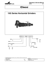
PART NUMBER FOR ORDERING PART NUMBER FOR ORDERING
1 Snap Ring . . . . . . . . . . . . . . . . . . . . . . . . . . . . . 37272 17 Motor Assembly . . . . . . . . . . . . . . . . . . . . . . . . 04614921
2 Exhaust Sleeve . . . . . . . . . . . . . . . . . . . . . . . . . 47571–1–F 18 Ball Bearing . . . . . . . . . . . . . . . . . . . . . . . . 46110
3 Hose Assembly . . . . . . . . . . . . . . . . . . . . . . . . 39907–7 19 End Plate . . . . . . . . . . . . . . . . . . . . . . . . . . 47564
4 Valve Assembly . . . . . . . . . . . . . . . . . . . . . . . . 47574 20 Pin . . . . . . . . . . . . . . . . . . . . . . . . . . . . . . . Y124–31
5 Screen . . . . . . . . . . . . . . . . . . . . . . . . . . . . . 47577 21 Cylinder Assembly (includes item 20) . . . . 47573
6 Valve Body . . . . . . . . . . . . . . . . . . . . . . . . . 47569 22 Rotor . . . . . . . . . . . . . . . . . . . . . . . . . . . . . . 04334884
7 O–Ring . . . . . . . . . . . . . . . . . . . . . . . . . . . . 47615 23 Blade (3 req’d) . . . . . . . . . . . . . . . . . . . . . . 46102
8 Bushing . . . . . . . . . . . . . . . . . . . . . . . . . . . 47572 24 End Plate . . . . . . . . . . . . . . . . . . . . . . . . . . 47560
9 Plug . . . . . . . . . . . . . . . . . . . . . . . . . . . . . . 31637 25 Ball Bearing . . . . . . . . . . . . . . . . . . . . . . . . 47559
10 Valve . . . . . . . . . . . . . . . . . . . . . . . . . . . . . . 47563 26 Collet Body . . . . . . . . . . . . . . . . . . . . . . . . 47570
11 O–Ring (2 req’d) . . . . . . . . . . . . . . . . . . . . 47576 27 Insert
12 Throttle . . . . . . . . . . . . . . . . . . . . . . . . . . . . . . . 47567 1/8” capacity . . . . . . . . . . . . . . . . . . . . . . . . 47568–1
13 Block Assembly . . . . . . . . . . . . . . . . . . . . . . . . 46619 3 mm capacity . . . . . . . . . . . . . . . . . . . . . . 47568–2
14 Snap Ring (3 req’d) . . . . . . . . . . . . . . . . . . Y110–2 28 Motor Housing
15 Screen (2 req’d) . . . . . . . . . . . . . . . . . . . . . 47497 for standard models . . . . . . . . . . . . . . . . . . 04562187
16 Air Block . . . . . . . . . . . . . . . . . . . . . . . . . . 47565 for “–EU” models . . . . . . . . . . . . . . . . . . . . 04613733
*
*
Sleeve . . . . . . . . . . . . . . . . . . . . . . . . . . . . . . . .
Warning Labels
for standard models . . . . . . . . . . . . . . . . . .
for “–EU” models . . . . . . . . . . . . . . . . . . . .
47550
48176–1
49883
*Not Illustrated

15
MAINTENANCE SECTION
Always turn off the air supply and disconnect the air
supply hose before installing, removing or adjusting any
accessory on this tool, or before performing any
maintenance on this tool. Failure to do so could result in
injury.
LUBRICATION
Whenever one of these Grinders is disassembled for
overhaul or replacement of parts, lubricate as follows:
1. Always wipe the Blades (23) with a light film of the
recommended oil before inserting them into the vane
slots.
2. Inject 0.5 to 1 cc of Ingersoll–Rand Lubricant No. 10
or a good quality high–speed spindle oil into the Valve
Body (6) after assembly.
DISASSEMBLY
The Model DG600G2 Pencil Grinder can be disassembled
into three major unit assemblies. They are the Valve Body
Assembly (4), the Motor Assembly (17) and the Air Block
Assembly (13). Do not disassemble any major unit
assembly that does not require repair.
General Disassembly Instructions
1. Do not disassemble the tool any further than necessary
to replace or repair damaged parts.
2. When grasping a tool or part in a vise, always use
leather–covered or copper–covered vise jaws to protect
the surface of the part and help prevent distortion. This
is particularly true of threaded members and housings.
Disassembly of the Tool
1. Remove Snap Ring (1) and Exhaust Sleeve (2),
allowing removal of Hose Assembly (3).
Do not grasp the Motor Housing (28) with pliers or
in a vise.
2. Carefully grasp the flats on the Hose Assembly in a
vise.
3. Using 9/16” wrench on flats on the Valve Body, loosen
and remove tool from Hose Assembly.
4. Reposition tool in vise and carefully grasp on the flats
of the Valve Body.
5. Remove Sleeve (29) by twisting and pulling upward.
6. Place tool horizontally in a suitable holding device and
clamp on one of the bottom two grooves of Motor
Housing (28).
7. Using 9/16” wrench on flats of Valve Body loosen and
remove from Motor Housing (28).
The Motor Assembly and Air Block Assembly will
be free to fall out of the Motor Housing when the
Housing is lifted from the Valve Body.
8. Remove the Motor Housing from the vise.
Disassembly of the Valve Body
1. Remove Screen (5).
2. Remove Throttle (12).
3. Using a pair of pliers remove Plug (9), being careful
not to damage.
4. Using needle nose pliers remove Valve (10) from Valve
Body.
5. Remove O–rings (11), if necessary.
6. Remove Bushing (8) and O–ring (7), if necessary.
Do not disassemble the Rotor components unless
damage is evident.
Disassembly of the Motor
1. Place Motor Assembly (17) in suitable holding device
with Ball Bearing (18) facing upwards.
2. Place a punch on the i.d. of the Bearing and tap to
remove Bearing, allowing removal of End Plate (24),
Cylinder (21) and Blades (23).
3. Place Rotor in special holding device, using wrench
47579 on flats of Collet body (26) loosen and remove
from Rotor (22).
4. Using a punch, tap on i.d. of Rotor and remove Bearing
(25) and End Plate (24).
Disassembly of the Air Block Assembly
1. Grasp Air Block Assembly (13) and pull apart from
Motor Assembly.
2. Remove Screen (15) and Snap Ring (14), if necessary.

16
MAINTENANCE SECTION
ASSEMBLY
General Assembly Instructions
1. Always press on the inner ring of a ball–type bearing
when installing the bearing on a shaft.
2. Always press on the outer ring of a ball–type bearing
when pressing the bearing into a bearing recess.
3. Whenever grasping a tool or part in a vise, always use
leather–covered or copper–covered vise jaws. Take
extra care with threaded parts and housings.
4. Always clean every part and wipe every part with a
thin film of oil before installation.
5. Apply a film of O–ring lubricant to all O–rings before
final assembly.
Assembly of the Air Block Assembly
1. Assemble Snap Ring (14) and Screen (15) to Air Block
(13).
Assembly of the Cylinder
1. Assemble Pin (20) to Cylinder (21).
Assembly of the Motor
1. Assemble End Plate (24) to Rotor (22).
2. Assemble Bearing (25) on Rotor.
3. Using a special holding device clamp on Rotor and
tighten Collet Body (26) to Rotor.
4. Screw Insert (27) on Collet Body.
5. Assemble Blades (23) to Rotor slots on Rotor – straight
side out.
6. Slide Cylinder over Rotor with Pin facing upward.
7. Assemble End Plate (19) to Rotor (22), aligning hole in
End Plate with Pin (20).
8. Assemble Bearing (18) to Rotor. Press on inner race of
Bearing.
Install Bearing with retainer toward End Plate.
9. Assemble Air Block Assembly (13) by aligning hole in
Block with Cylinder Pin and assemble components to
Motor Housing (28).
Assembly of the Valve Body
1. Apply a thin coat of O–ring lubricant to O–rings (11)
and install them in the grooves in the Valve Body (6).
2. Assemble O–ring and Bushing (8) in front end of Valve
Body (6).
3. Insert Valve (10) into Valve Body and rotate Valve
until the hole aligns with the slot in the Valve Body.
4. Insert Plug (9) into hole of Valve.
5. Slide Throttle (12) over front end of Valve Body.
6. Insert Screen (5) in rear of Valve Body.
Assembly of the Tool
1. Insert Motor Assembly with Air Block Assembly
attached into Housing (28).
2. Assemble Throttle (12) to Valve Body.
The Throttle must rotate freely when the tool is
completely assembled.
3. Assemble Valve Body Assembly (4) to Housing.
4. Place tool in special holding device and clamp on one
of the bottom two grooves.
5 Rotate the Throttle to the ON position and tighten
Valve Body Assembly to Housing using a 9/16 inch
wrench on flats of Valve Body.
6. Rotate the Throttle to the OFF position and remove
tool from the special holding device. Grasp Insert
Assembly on front end of tool to ensure tool turns
freely.
7. Carefully grasp the flats on the threaded end of the
Valve Body in vise with the Collet Body (26) upward.
8. Lubricate Sleeve (29) and slide over top of tool.
9. Slide Exhaust Sleeve (2) and Snap Ring (1) over Hose
Assembly (3).
10. Remove the assembled tool from the vise and connect
the Hose Assembly to the Valve Body.
11. Slide Exhaust Sleeve to groove in Valve Body and
secure Snap Ring.

17
MAINTENANCE SECTION
TROUBLESHOOTING GUIDE
Trouble Probable Cause Solution
Low power or low free speed Insufficient air pressure Check air line pressure at the Inlet of the Tool.
It must be 90 psig (6.2 bar/620 kPa).
Insufficient lubrication Inject 0.5 to 1 cc of the recommended oil into
the Air Inlet.
Clogged Muffler Replace the Muffler.
Worn or broken Blades Install a complete set of new Blades.
Worn or broken Cylinder Replace the Cylinder.
Rough operation Improper lubrication or dirt
buildup
Inject 3 cc of a clean, suitable cleaning solution into
the Inlet, operate the tool for 30 seconds
and immediately inject 0.5 to 1 cc of the
recommended oil into the Inlet and run the
Grinder long enough to coat the internal parts
with the oil.
Worn or broken Rear Rotor Examine each bearing. Replace the Rear Rotor
Bearing or Front Rotor Bearing if it is worn or broken. Replace the Rotor
Bearing Assembly if the front rotor bearing is
worn or broken.
Excessive runout Loose Spindle Nut Tighten the Spindle Nut until snug.
Worn or damaged Spindle or Replace the damaged component and retest.
Spindle Nut
Worn or damaged Front Spindle Examine each Bearing. Replace any damaged
Bearing or Rear Spindle or worn Bearings.
Bearing
SAVE THESE INSTRUCTIONS. DO NOT DESTROY.
/