Page is loading ...

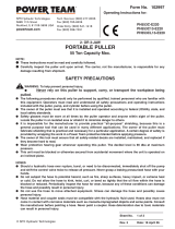
1 54033 Pad (For 54035 Assy.)
54018 Pad (For 54034 Assy.)
2 Mini-Orbital Head Assemblies
54034 1/4"-20 Tread-Type
54035 Locking-Type
3 95613 Retaining Ring
4 54145 Roloc Sub Assembly
5 95612 Bearing Shield
6 50722 Balancer Bearing (2)
7 95558 Retaining Ring
8 54036 Counterweight
9 54124 Balancer Shaft
10 57528 Motor Shaft
11 56047 Key
12 57059 Lock Ring
13 95973 Washer
14 57055 Front Ring
15 57088 Bearing
16 57057 Front Bearing Plate
17 57113 Rotor/Blade Set
18 57058 Cylinder (Incl. 95971 Pin)
19 95971 Pin
20 57056 Rear Bearing Plate
21 01206 Bearing
22 57054 Rear Ring
23 95626 Retaining Ring
24 95979 Pin
25 56846 Lever
26 57529 Housing - Model 57500
57523 Housing - Model 57502
57533 Housing - Model 57503
57520 Housing - Model 57504
27 95697 Retaining Ring
28 01025 O-Ring (2)
29 01477 Valve Stem
30
Speed Regulators Plugs
57531 Non Reg. Plug
57064 Regulator Plug (Optional)
57053 Recessed Plug (Optional)
31 56027 Muffler Insert (3)
32 69359 Muffler Body
33 01464 Seal
34 01472 Tip Valve
35 01468 Conical Spring
36 01494 Inlet Bushing
Always operate, inspect and maintain this tool in accordance with the Safety Code for portable air
tools (ANSI B186.1) and any other applicable safety codes and regulations. Please refer to
Dynabrade’s Warning/Safety Operating Instructions for more complete safety information.
PD07•03R
May, 2017
Supersedes PD04•15, PD01•02
Air Motor and Machine Parts
Models:
57500 – 5,000 RPM
57501 – Versatility Kit
57502 – 7,500 RPM
57503 – 5,000 RPM
57504 – 7,500 RPM
Mini-Dynorbital
®
Supreme
95262 14mm Wrench
95263 17mm Wrench
95281 19mm Wrench
54034 Head Assembly54035 Head Assembly
Note: To order replacement parts specify the model and serial number of your machine.
A
8
A
2
O
1
O
1
1
2
10
12
13
14
15
16
17
18
20
21
26
24
25
22
23
33
34 35 36
27
28
29
30
6
7
8
31 32
19
11
5
4
3
23 N•m
T
28 N•m
T
Index Key
No. Part # Description
A
T
O
Adhesive:
A
2
= Loctite #271
A
8
= Loctite #567
Oil: O
1
= Air Lube
Torque: N•m x 8.85 = In. - lbs.
KEY
A
2
8
7
5
9
3
6

Important Operating, Maintenance and Safety Instructions
Carefully read all instructions before operating or servicing any Dynabrade
®
Abrasive Power Tool.
Warning: Hand, wrist and arm injury may result from repetitive work motion and overexposure to vibration.
Important: All Dynabrade Rotary Vane air tools must be used with a Filter-Regulator-Lubricator to maintain all warranties.
Operating Instructions:
Warning: Eye, face, respiratory, sound and body protection must be worn while operating power tools. Failure to do so may result in serious injury or death.
Follow safety procedures posted in workplace.
1. With power source disconnected from tool, securely fasten abrasive/accessory on tool.
2. Install air fitting into inlet bushing of tool.
Important: Secure inlet bushing of tool with a wrench before attempting to install the air fitting to avoid damaging valve body housing.
3. Connect power source to tool. Be careful not to depress throttle lever in the process.
4. Check tool speed with tachometer. If tool is operating at a higher speed than the RPM marked on the tool or operating improperly,
the tool should be
serviced to correct the cause before use.
5. Air tools are not intended for use in explosive atmospheres and are not insulated for contact with electrical power sources. Sa
nding/Grinding certain
materials can create explosive dust. It is the employers responsibility to notify the user of acceptable dust levels. Sanding/Grinding can cause sparks
which can cause fires or explosions. It is the users responsibility to make sure the work area is free of flammable materials.
Maintenance Instructions:
1. Check tool speed regularly with a tachometer. If tool is operating at a higher speed than the RPM marked on the tool, the tool should be serviced to
correct the cause before use.
2. Some silencers on air tools may clog with use. Clean and replace as required.
3. All Dynabrade Rotary V
ane air motors should be lubricated. Dynabrade recommends one drop of air lube per minute for each 20 SCF
M (example: if
the tool specifications state 40 SCFM, set the drip rate of your filter-lubricator at 2 drops per minute).
Dynabrade Air Lube (P/N 95842: 1 pt. 473 ml.) is recommended.
4. It is strongly recommended that all Dynabrade rotary vane air tools be used with a Filter-Regulator-Lubricator to minimize the possibility of misuse due
to unclean air, wet air or insufficient lubrication. Dynabrade recommends the following: 11405 Air Line Filter-Regulator-Lubricator — Provides accurate
air pressure regulation, two-stage filtration of water contaminants and micro-mist lubrication of pneumatic components. Operates 40 SCFM @ 100 PSIG
has 3/8" NPT female ports.
5. Use only genuine Dynabrade replacement parts. To reorder replacement parts, specify the Model #, Serial #, and RPM of your machine.
6. A Motor Tune-Up Kit (P/N 96109) is available which includes assorted parts to help maintain motor in peek operating condition.
7. Mineral spirits are recommended when cleaning the tool and parts. Do not clean tool or parts with any solvents or oils containing acids, esters,
keytones, chlorinated hydrocarbons or nitro carbons.
8. DO NOT clean or maintain air tools with chemicals that have a low flash point (example: WD-40
®
).
2
One Year Warranty
Following the reasonable assumption that any inherent defect which might prevail in a product will become apparent to the user within one year from the date of
purchase, all equipment of our manufacture is warranted against defects in workmanship and materials under normal use and service. We shall repair or
replace at our factory, any equipment or part thereof which shall, within one year after delivery to the original purchaser, indicate upon our examination to have
been defective. Our obligation is contingent upon proper use of Dynabrade tools in accordance with factory recommendations, instructions and safety practices.
It shall not apply to equipment which has been subject to misuse, negligence, accident or tampering in any way so as to affect its normal performance. Normally
wearable parts such as bearings, contact wheels, rotor blades, etc., are not covered under this warranty.
•
Important: User of tool is responsible for following accepted safety codes such as those published by the American National Standards Institute (ANSI).
•
Operate machine for one minute before application to workpiece to determine if machine is working properly and safely before work begins.
•
Always disconnect power supply before changing abrasive/accessory or making machine adjustments.
•
Inspect abrasives/accessories for damage or defects prior to installation on tools.
•
Please refer to Dynabrade’s Warning/Safety Operating Instructions Tag (Reorder No. 95903) for more complete safety information.
Notice
All Dynabrade motors use the highest quality parts and metals available and are machined to exacting tolerances. The failure of quality pneumatic motors can most
often be traced to an unclean air supply or the lack of lubrication. Air pressure easily forces dirt or water contained in the air supply into motor bearings causing
early failure. It often scores the cylinder walls and the rotor blades resulting in limited efficiency and power. Our warranty obligation is contingent upon proper use of
our tools and cannot apply to equipment which has been subjected to misuse such as unclean air, wet air or a lack of lubrication during the use of this tool.
Safety Instructions:
Products offered by Dynabrade should not be converted or otherwise altered
from original design without expressed written consent from Dynabrade, Inc.
Models Motor Motor Pad Dia. Orbit Diameter Sound Air Flow Rate Weight Length Height
HP (W) RPM Inch (mm) Inch (mm) Level SCFM (LPM) Pound (kg) Inch (mm) Inch (mm)
5,000RPM .05 (37) 5,000 3/4 (19), 1-1/4 (32) 3/16 (5) 70 dB(A) 6 (170) 1.7 (0.8) 5 (127) 3-5/8 (92)
7,500RPM .05 (37) 7,500 3/4 (19), 1-1/4 (32) 3/16 (5) 70 dB(A) 6 (170) 1.7 (0.8) 5 (127) 3-5/8 (92)
Additional Specifications: Air Inlet Thread 1/4" NPT • Hose I.D. 1/4" (6mm) • Air Pressure 90 PSIG (6.2 Bars)

Disassembly/Assembly Instructions - Mini-Dynorbital
®
Supreme
Important: Manufacturer’s warranty is void if tool is disassembled before warranty expires.
A Motor Repair Kit (57525) is available which contains special tools for disassembly/assembly. Please refer to parts breakdown for part identification.
Motor Disassembly:
1. Disconnect tool from power source.
2. Invert machine and secure in vise, using 57092 Collar (supplied in 57525 Repair Kit) or padded jaws. Remove sanding pad.
3. Insert 56058 Lock Ring Tool (supplied in 57525 Repair Kit) into corresponding tabs of lock ring and unscrew. Motor may now be lifted out for service.
4. Remove lock ring, washer, front ring and rear ring from motor. Remove 95626 Retaining Ring, upper motor may now be disassembled.
5. Remove the rear plate and the cylinder assembly by securing the cylinder in a bearing separator gripped on the cylinder exhaust and extra pocket area.
Push the motor shaft through the bearing.
6. Remove the rotor, vanes and key from the motor shaft. Remove the front plate using a small (#2) arbor press. Support the edges of the
front plate while pressing on the small end of the motor shaft.
a.) If, during step 7, the front plate and bearing remain together, press bearing out of the front plate using 57091 Press Tool (supplied in
57525 Repair Kit).
b.) If, during step 7, the front plate and 57088 Bearing remains on the motor shaft, it can be removed with a bearing separator.
7. Remove 01206 Bearing from the rear plate by using a bearing press tool.
8. Disassemble the head assembly as follows:
a.) Place head assembly into a soft jaw vise. Using a thin screwdriver, pick out the end of retaining ring and peel out.
b.) Screw threaded portion of the 54121 Bearing Puller (supplied in 57525 Repair Kit) onto the balancer shaft and using the slider weight, pull out.
c.) Remove 95558 Retaining Ring. Press off 57022 Bearings and remove loose parts.
9. If during step 8, the 57022 Bearings remain in the head assembly, they can be removed by heating the counterweight and using either an inside
bearing puller or a blind hole bearing puller.
Motor Disassembly Complete.
To Assemble:
Important: Be certain all parts are clean and in good repair before assembling.
1. Assemble the balancer assembly as follows:
a.) Install 95613 Retaining Ring onto 54145 Roloc Sub Assembly. Install 95612 Shield with convex face toward head of 54145 Roloc Sub Assembly.
b.) Remove three of the four bearing seals from the 50722 Bearings. Press fit 50722 Bearings onto 54145 Roloc Sub Assembly with the remaining
bearing seal facing 95612 Shield. Install 95558 Retaining Ring.
2. Place 54036 Counterweight into a soft jaw vise with the large end up.
3. Apply a slight amount #271 Loctite
®
(or equivalent) in several places around the outside diameter of the 50722 Bearings and slide into the 54036
Counterweight until 50722 Bearings are firmly seated at bottom. Squeeze 95613 Retaining Ring into groove to complete the assembly. Remove from vise.
4. Press 57088 Bearing onto the Motor Shaft down to the shoulder.
5. Press 57057 Front Bearing Plate onto 57088 Bearing and check for smooth rotation.
6. Place the 57113 Rotor and 56047 Key on the 57528 Motor Shaft. Place the vanes into the rotor slots.
Note: Vanes should be lightly lubricated with Dynabrade Air Lube P/N 95842 (or equivalent) before installation into rotor slots.
7. Place 57058 Cylinder Assembly over rotor. The “short” line-up pin goes toward the front plate.
8. Place 57056 Rear Bearing Plate (with 01206 Rear Bearing pressed into place) over shaft and “long” end of line-up pin and press fit in place.
9. Place 95626 Retaining Ring in groove.
10. Place 57054 Rear Ring over the rear plate and line-up pin. Turn the motor over and place 57055 Front Ring over the front plate making sure that the
“legs and fingers” on the front and rear rings line-up. Also the small cut-outs on both rings should line-up with the square holes in the cylinder/endplate
assembly. Place 95973 Washer and 57059 Lock Ring onto the front ring with 1 drop of pneumatic tool oil spread between the washer and lock ring.
11. Secure motor housing in vise, using 57092 Collar or padded jaws. Spread 2-3 drops of pneumatic tool oil around the housing bore and slide motor
assembly in housing. Note: Be certain line-up pin enters the pocket in bottom of the housing and the “legs” of the rings stay in line.
12. Tighten lock ring with 56058 Lock Ring Tool torque to 28 N•m/250 in. - lbs.
Motor Assembly Complete. Please allow 30 minutes for adhesives to cure before operating tool.
Valve and Speed Regulator Assemblies:
1. Secure housing in vice using 57092 Collar or padded jaws.
2. Remove inlet bushing, 01468 Spring, valve and seal from housing.
3. Remove 95697 Retaining Ring. Press the spread regulator and valve stem out of the housing. Remove the 01025 O-Rings (2).
4. Place new 01025 O-Rings (2) on the speed regulator and place in housing with valve stem. Install new 95967 Retaining Ring.
5. Place seal in housing. Using tweezers or needle nose pliers, place the valve in the housing so that its pin goes into the valve stem hole. Place 01468
Spring into the housing so the small end is toward the tip valve.
6. Spread 1 drop of #271 Loctite
®
(or equivalent) around the threads of the inlet bushing and tighten into housing torque to 23 N•m/200 in. - lbs.
Tool Assembly Complete. Please allow 30 minutes for adhesives to cure before operating tool.
Note: 5,000 RPM Motors should operate at between 4,500 and 5,000 RPM at 6.2 bar (90 PSIG) and for 7,500 RPM Models between 7,500 and 8,250 RPM at
6.2 bar (90 PSIG). RPM should be checked with a tachometer or a magnetic tach such as Dynabrade’s P/N 96368. Before operating, we recommend that 2-3
drops of Dynabrade Air Lube P/N 95842 (or equivalent) be placed directly into the air inlet with throttle lever depressed. Operate the machine for approximately
30 seconds before application to work piece to determine if machine is working properly and safely and to allow lubrication oils to properly dispense
through machine.
Loctite
®
is a registered trademark of the Loctite Corp.
3

Mini-Dynorbital Sanding Pads/Unit = 10 each
Optional Accessories
96109 Motor Tune-Up Kit:
•
Includes assorted parts to help
maintain and repair motor.
57525 Motor Repair Kit:
•
Includes special tools for proper
disassembly/assembly of the
Mini-Dynorbital
®
Supreme.
Disc Abrasive Grit 1000
Diameter (9 Micron)
3/4" 93183
1-1/4" 93191
3/4" Discs: 75/Sheet; 1500 discs = unit.
1-1/4" Discs: 25/Sheet; 1500 discs = unit.
Available in complete sheets only.
Micro-Finishing Film Discs – PSA Mounted/Aluminum Oxide
Grade
Disc Dia. Very Fine Medium
3/4" 90856 90858
1-1/4" 90860 90862
3/4" Discs: Unit = 225 Discs. 1-1/4" Discs: Unit = 125 Discs.
Non-Woven Nylon Discs – Mount to Hook ’n Loop Pads
Disc Abrasive Grit
Diameter 80 120 180 220
3/4" 93271 93272 93274 93275
1-1/4" 93280 93281 93283 93284
3/4" Discs: 75/Sheet; 1500 discs = unit. 1-1/4" Discs: 25/Sheet; 1500 discs = unit. Available in complete sheets only.
Coated Silicon Carbide Abrasive Sanding Discs/PSA
DYNABRADE
®
DYNABRADE, INC.,
8989 Sheridan Drive
•
Clarence, NY 14031-1490
•
Phone: (716) 631-0100
•
Fax: 716-631-2073
•
International Fax: 716-631-2524
DYNABRADE EUROPE S.àr.l.,
Zone Artisanale
•
L-5485 Wormeldange—Haut, Luxembourg
•
Telephone: 352 76 84 94 1
•
Fax: 352 76 84 95 1
© DYNABRADE, INC., 2007 PRINTED IN USA PD07.03R_Rev.1_01/07
Visit Our Web Site: www.dynabrade.com Email: [email protected]
80030 Training and Maintenance Test Equipment Kit:
•
80025 Load Cell measures tool RPM under load and useful for training operators
for proper buffing pressure/operation. Electronic tachometer pick-up securely
fastens to wear plate.
•
94315 Pressure Gage to ensure peak operating performance.
•
95842 Air Lube formulated for pneumatic tools. Prevents rust and formation of
gum/sludge for longer tool operation with greater power and less downtime.
•
96368 Tachometer used to measure tool RPM.
Filter-Regulator-Lubricator 11405
40 SCFM @ 100 PSIG, 3/8" NPT female ports.
(1,133 LPM) (6.9 Bar)
•
Provides accurate air pressure regulation,
two stage filtration of water/contaminants
and lubrication of pneumatic components.
1/4" Sponge
Vinyl Face
1/4" Sponge
60 Duro Rubber
Note: All Pads 5,000 RPM maximum. To mount pads that have 1/4"-20 female thread directly to tool for conventional rotary action, use 54021 Adapter.
1/4"-20
Female
Thread
1/4"-20
Female
Thread
• For optional 54029, 54030 or 54035
Sanding Head.
• Order Vinyl Face Pads 54091 or
54092 for wet sanding operations.
• For use with non-woven
nylon discs.
Foam Facing
Sponge
Locking-Type
Male Thread
54017 3/4" Medium/Rubber 1/4"-20 Female For PSA Discs
54018 1-1/4" Medium/Rubber 1/4"-20 Female For PSA Discs
54031 1-1/4" Soft Locking-Type For PSA Discs
54087 3/4" Soft/Vinyl 1/4"-20 Female For PSA Discs
54088 1-1/4" Soft/Vinyl 1/4"-20 Female For PSA Discs
54089 3/4" Hook ‘n Loop 1/4"-20 Female Non-Woven Nylon Discs
54090 1-1/4" Hook ‘n Loop 1/4"-20 Female Non-Woven Nylon Discs
54091 3/4" Medium/Vinyl 1/4"-20 Female For PSA Discs
54092 1-1/4" Medium/Vinyl 1/4"-20 Female For PSA Discs
Part No. Pad Diameter Description/Face Thread Type Comments
“Soft” Density “Medium” Dual-Density “Hook ’n Loop” “Soft” Locking-Type
1/4"-20
Female
Thread
/