Page is loading ...

Parts Page Reorder No. PD10•18
Effective April, 2010
Mini-Dynorbital
®
Silver Supreme Sander
Air Tool Manual – Safety, Operation and Maintenance
Models:
69500 - 5,000 RPM, Thread-Type (1/4"-20)
69502 - 7,500 RPM, Locking-Type
69503 - 5,000 RPM, Locking-Type
69504 - 7,500 RPM, Thread-Type (1/4"-20)
SAFETY LEGEND
WARNIN
G
WARNING
Read and understand tool manual before
work starts to reduce risk of injury to
operator, visitors, and tool.
WARNING
Eye protection must be worn at all times,
eye protection to conform to ANSI Z87.1.
WARNING
Respiratory protection to be used when exposed to
contaminants that exceed the applicable threshold
limit values required by law.
WARNING
Practice safety requirements. Work alert,
have proper attire, and do not operate tools under
the influence of alcohol or drugs.
WARNING
Ear protection to be worn when exposure to sound,
exceeds the limits of applicable Federal, State or
local statues, ordinances and/or regulations.
WARNING
Air line hazard, pressurized supply lines and flexible
hoses can cause serious injury. Do not use damaged,
frayed or deteriorated air hoses and fittings.
Read and understand this tool manual before operating your air tool. Follow all safety rules for the protection of operating personnel
as well as adjacent areas. Always operate, inspect and maintain this tool in accordance with the American National Standards
Institute (ANSI) Safety Code for Portable Air Tools – B186.1. For additional safety information, refer to Safety Requirements for the
Use, Care and Protection of Abrasive Wheels – ANSI B7.1, Code of Federal Regulation – CFR 29 Part 1910, European Committee for
Standards (EN) Hand Held Non-Electric Power Tools – Safety Requirements and applicable State and Local Regulations.
SAVE THIS DOCUMENT, EDUCATE ALL PERSONNEL
Air Powered Sander
WARNING
Some dust created by sanding, grinding, drilling, and other construction activities contain chemicals known to cause cancer, birth
defects or other reproductive harm. Some examples of these chemicals are:
• Lead from lead-based paints
• Crystalline silica from bricks and cement and other masonry products
• Arsenic and chromium from chemically treated lumber
Your risk from these exposures varies, depending on how often you do this type of work. To reduce your exposure to these chemicals: work in a well
ventilated area, and work with approved safety equipment, such as those dust masks that are specially designed to filter out microscopic particles.
FIND THE MOST CURRENT OFFERING OF SUPPORT DOCUMENTS AND ACCESSORIES @ WWW.DYNABRADE.COM
3/16" Random
Orbit Motion
SAFETY/OPERATING INSTRUCTIONS
Carefully Read all instructions before operating or servicing any Dynabrade
®
Abrasive Power Tool.
Products offered by Dynabrade are not to be modified, converted or otherwise alerted from the original design.
Tool Intent: Mini-Dynorbital
®
Silver Supreme Sander is used for sanding and finishing a variety of materials including wood, metal, plastic, fiberglass, solid
surfaces, composites, rubber, glass and stone. Using 3/4" - 1-1/4" diameter back-up pads. Use of pads greater than 1-1/4" diameter may increase vibration level.
Do Not Use Tool For Anything Other Than Its Intended Applications.
Warning: This power tool is not intended for use in potentially explosive atmospheres and is not insulated against contact with electrical power.
Training: Proper care, maintenance, and storage of your tool will maximize its performance.
• Employer's Responsibility – Provide Mini-Dynorbital
®
Silver Supreme Sander operators with safety instructions and training for safe use of tools and accessories.
Accessory Selection:
Warning:
• Abrasive/accessory RPM (speed) rating MUST be approved for AT LEAST the tool RPM rating.
• DO NOT USE grinding wheels or cut-off wheels.
• Back-up pad must always be used, abrasive is not to exceed more than 1/4" beyond pad edge.
• Before mounting an accessory, inspect for defects. Do not use defective accessories.
• Only use recommended fittings and air line sizes. Air supply hoses and air hose assemblies must have a minimum working pressure rating of 150 PSIG
(10 Bars, g) or 150 percent of the maximum pressure produced in the system, whichever is higher. (See tool Machine Specifications table.)

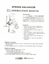
To Tool Station
Closed Loop Pipe System
(Sloped in the direction of air flow)
Ball
Valve
Ball
Valve
Filter
Coupler
Regulator
Lubricator
Air Flow
Drain
Valve
Drain
Valve
Air Tool
Air Compressor
and Receiver
Drain
Valve
Air Hose
Air Flow
Refrigerated
Air Dryer
2
Filter
Regulator
Lubricator
90 PSIG
(6.2 Bar)
SAFETY/OPERATING INSTRUCTIONS
Warnings:
• Always wear eye protection. Operator of tool is responsible for following: accepted eye, face, respiratory, hearing and body protection.
• Working end of the air tool has potential hazard of cutting.
• Be sure that any loose clothing, hair and all jewelry is properly restrained.
• Tool RPM must never exceed abrasive/accessory RPM rating. Check accessory manufacturer for details on maximum operating speed or special mounting instructions.
• Make sure that work area is uncluttered, and visitors are at a safe range from the tools and debris.
• Potentially explosive atmospheres can be caused by dust and fumes resulting from work. Always use dust extraction or suppression systems which are suitable for the
material being processed.
• Use only appropriately sized abrasive sanding discs properly secured and centered to the backing pad provided with the air sander.
• Do not free spin the tool away from the work surface with an abrasive sanding disc attached. The sanding disc may detach from the back-up pad causing injury.
• Always start the tool with the sanding abrasive against the work. Stop the air flow to the tool as it is removed from the work.
• Air tools are not intended for use in explosive atmospheres and are not insulated for contact with electric power sources.
• Work may generate hazardous dust.
• Ensure that sparks and debris resulting from work do not create a hazard.
Cautions
• Hand, wrist and arm injury may result from repetitive work, motion and overexposure to vibration.
• After installing the accessory, before testing or use and/or after assembling tool, the tool must be started at a reduced speed to check for good balance. Gradually increase
tool speed. DO NOT USE if tool vibration is excessive. Correct cause, and retest to insure safe operation.
• Release the throttle lever in case of an interruption of the energy supply.
Additional Information:
• Install air fitting into inlet bushing of tool. Important: Secure inlet bushing of tool with a wrench before attempting to install the air fitting to avoid damaging
valve body housing.
• BEFORE MOUNTING AN ACCESSORY, after all tool repairs and whenever a Mini-Dynorbital
®
Silver Supreme Sander is issued for use, check the free speed (RPM) with the
back-up pad securely fastened without any type of sanding accessory attached to the back-up pad. The air pressure must be set to 90 PSIG with the tool
running. Checking the RPM requires either a strobe or a magnetic tachometer. If tool is operating at a higher speed than the RPM marked on the tool housing, or operating
improperly, the tool must be serviced and corrected before use.
• Use only Dynabrade weight-mated pads to maintain low vibration levels.
• Connect air tool to power source. Be careful NOT to depress throttle lever in the process.
• Do not expose air tool to inlet pressure above 90 PSIG or (6.2 Bars).
• Keep hand and clothing away from working end of the air tool.
• Proceed with caution in unfamiliar surroundings. Hidden hazards may exist, such as electricity or other utility lines.
• Always be aware of bystanders in work areas.
• Use a vise or clamping device to hold work piece firmly in place.
• Do not apply excessive force on tool or apply “rough” treatment to it.
• When applying the sander to a work surface start-on and stop-off when completed.
• Always work with a firm footing, posture and proper lighting.
• Disconnect tool from air supply when changing recommended accessories.
• This tool is rear exhaust. Exhaust may contain lubricants, vane material, bearing grease, and other materials flushed thru the tool.
Report to your supervisor any condition of the tool, accessories, or operation you consider unsafe.
Air System
1 DROP/MIN.
20 SCFM
LUBRICATOR SETTING
•
Ideally the air supply should be free of moisture.
To facilitate removing moisture from air supply, the
installation of a refrigerated air dryer after the
compressor and the use of drain valves at each
tool station is recommended.
•
Dynabrade Air Power Tools are designed to
operate at 90 PSIG (6.2 Bar/620 kPa) maximum
air pressure at the tool inlet, when the tool is
running. Use recommended regulator to control
air pressure.
➤
➤
➤
➤
➤
➤
90 PSIG MAX
(6.2 Bar)

Maintenance Instructions
Important: To keep tool safe a preventative maintenance program is recommended whenever portable power tools are used.
•
Use only genuine Dynabrade replacement parts to insure quality. To order replacement parts, specify Model#, Serial# and RPM of your air tool.
•
It is strongly recommended that all Dynabrade rotary vane air tools be used with a Filter-Regulator-Lubricator to minimize the possibility of misuse due
to unclean air, wet air or insufficient lubrication. Dynabrade recommends the following: 10681 Air Filter-Regulator-Lubricator (FRL) – Provides accurate
air pressure regulation and two stage filtration of water contaminates.
•
Dynabrade recommends one drop of air lube per minute for each 20 SCFM (example: if the tool specification states 40 SCFM, set the drip rate on the
filter-lubricator to 2 drops per minute). Dynabrade Air Lube (P/N 95842: 1 pt 473 ml) is recommended.
Routine Preventative Maintenance:
•
Regularly check the free speed (RPM) of the Mini-Dynorbital
®
Silver Supreme Sander. The speed (RPM) is checked with the back-up pad securely
fastened without any type of sanding accessory attached to the back-up pad. The air pressure must be set to 90 PSIG with tool running. Checking the
RPM requires either a strobe or a magnetic tachometer. This procedure is required after all tool repairs and whenever a tool is issued for use. If the tool
is operating at a higher speed than the RPM marked on the tool housing, or operating improperly, the tool must be serviced and corrected before use.
•
Mineral spirits are recommended when cleaning the tool and parts. Do not clean tool or parts with any solvents or oils containing acids, esters,
ketones, chlorinated hydrocarbons or nitro carbons.
•
DO NOT clean or maintain tools with chemicals that have a low flash point (example: WD-40
®
).
•
A Tune-Up Kit is available, see specific kit number on page 7.
•
Air tool stampings must be kept legible at all times, if not, reorder and replace. User is responsible for maintaining specification information i.e.:
Model #, S/N, and RPM.
•
Blow air supply hose out prior to initial use.
•
Visually inspect air hoses and fittings for frays, visible damage and signs of deterioration. Replace damaged or worn components.
•
Refer to Dynabrade's Warning/Safety Operating Instructions Tag (Reorder No. 95903) for safety information.
After maintenance is performed on tool, add a few drops of Dynabrade Air Lube (P/N 95842) to the air line and start the tool a few times to lubricate air motor.
Check for excessive tool vibration.
Handling and Storage:
•
Protect tool inlet from debris (See Notice Below).
•
DO NOT carry tool by air hose.
•
Protect abrasive accessories from exposure to water, solvents, high humidity, freezing temperature and extreme temperature changes.
•
Store accessories in protective racks or compartments to prevent damage.
Notice
All Dynabrade motors use the highest quality parts and materials available and are machined to exacting tolerances. The failure of quality pneumatic motors
can most often be traced to an unclean air supply or the lack of lubrication. Air pressure easily forces dirt or water contained in the air supply into motor
bearings causing early failure. It often scores the cylinder walls and the rotor blades resulting in limited efficiency and power. Our warranty obligation is
contingent upon proper use of our tools and cannot apply to equipment which has been subjected to misuse such as unclean air, wet air or a lack of
lubrication during the use of this tool.
3
Reference Contact Information
1. American National Standards
Institute – ANSI
25 West 43
rd
Street
Forth Floor
New York, NY 10036
Tel: 1 (212) 642-4900
Fax: 1 (212) 398-0023
3. Power Tool Institute, Inc.
P.O. Box 818
Yachata, Oregon 97498-0818
Tel: 1 (503) 547-3185
Fax: 1 (503) 547-3539
4. European Committee for Standardization
Rue de Stassart 36
B - 1050 Brussels, Belgium
2. Government Printing Office – GPO
Superintendent of Documents
Attn. New Orders
P.O. Box 371954
Pittsburgh, PA 15250-7954
Tel: 1 (202) 512-1803
Lifetime Warranty
All Dynabrade portable pneumatic power tools are rigorously inspected and performance tested in our factory before shipping to our customers. If a Dynabrade tool develops
a performance problem and an inherent defect is found during normal use and service, Dynabrade will warrant this tool against defects in workmanship and materials for
the lifetime of the tool. Upon examination and review at our factory, Dynabrade shall confirm that the tool qualifies for warranty status, and will repair or replace the tool at
no charge to the customer. Normally wearable parts and products are NOT covered under this warranty. Uncovered items include bearings, contact wheels, rotor blades,
regulators, valve stems, levers, shrouds, guards, O-rings, seals, gaskets and other wearable parts. Dynabrade’s warranty policy is contingent upon proper use of our tools
in accordance with factory recommendations, instructions and safety practices. It shall not apply to equipment that has been subjected to misuse, negligence, accident or
tampering in any way so as to affect its normal performance. To activate lifetime warranty, customer must register each tool at www.dynabrade.com. Dynabrade will not
honor lifetime warranty on unregistered tools. A one-year warranty will be honored on all unregistered portable pneumatic power tools. Lifetime warranty applies only to
portable pneumatic tools manufactured by Dynabrade, Inc. in the USA. Lifetime warranty applies only to the original tool owner; warranty is non-transferable.

A
8
A
10
A
2
Mini-Dynorbital
®
Silver Supreme Sanders
4
Note: To order replacement parts specify the Model # and Serial # of your machine.
O
T
A
Oil: O
1
= Air Lube
Adhesive: A
2
= Loctite #271
A
8
= Loctite #567
A
10
= Loctite #243
Torque: N•m x 8.85 = In. - lbs.
KEY
5
O
1
O
1
O
1
O
1
8
7
9
1
1
4
11
10
12
13
14
15
16
18
13
21
19
20
22
24
25
28
29
30
27
17
Exhaust
Assembly
(See Below)
For Models:
69500, 69502, 69503, 69504
28 N•m
T
23 N•m
T
4.5 N•m
T
O
1
Exhaust Assembly
32
34
Index Key
No. Part # Description
33
31
23
26
1 Sanding Pad
54037 Locking-Type
54018 Threaded Type (1/4"-20)
2 95679 1/4"-20 Stud
3 54145 Retainer Assembly
4 95613 Retaining Ring
5 95612 Bearing Shield
6 50722 Bearing (2)
7 95558 Retaining Ring
8 54081 Shaft Balancer
9 56047 Key
10 59058 Lock Ring
11 59057 “Top Hat” Seal
12 59083 Felt
13 58368 Bearing (2)
14 57893 Front Bearing Plate
15 57113 Rotor/Blade Set
16 69350 Cylinder
17 69352 Seal
18 57891 Rear Bearing Plate
19 Housing - See Chart
20 69360 Throttle Lever
21 94590 Pin
22 57041 Comfort Platform
23 98459 O-Ring
24 58363 Valve Stem
25 58609 Non-Adjustable
Speed Regulator
26 01025 O-Ring (2)
27 95697 Retaining Ring
28 01464 Seal
29 58365 Tip Valve
30 01468 Spring
31 01494 Inlet Bushing
32 56027 Muffler Insert (2)
33 69359
Muffler Body
34 69272 Muffler Assembly
35 97166 Hanger
Model Housing P/N
69500 69522
69502 69523
69503 69524
69504 69525
6
3
35
Always follow adhesive manufacturers
cleaning and priming recommendations.
2

Motor Assembly/Disassembly Instructions - Mini-Dynorbital
®
Important: Manufacturers warranty is void if tool is disassembled before warranty expires.
A Repair Kit P/N 57525, is available which includes special repair tools for correct disassembly/assembly of the sander.
To Disassemble:
1. Disconnect sander from air supply.
2. Invert the sander, and place the 57092 Repair Collar (supplied in the 57525 Repair Kit) around the housing and secure in a vise. Padding
can be used on the vise jaws to protect the housing. Important: Do not over tighten the sander in the vise. If the sander is held too tight the
removal of the lock ring and air motor will be difficult.
3. Remove back-up pad.
4. Insert 56058 Lock Ring Tool (supplied in 57525 Repair Kit) into the corresponding tabs of lock ring. Loosen the 59058 Lock Ring
turning it counterclockwise.
5. Remove the 59058 Lock Ring from the air motor assembly.
6. Fasten a 2 in. bearing separator (P/N 96346 available) around the 69350 Cylinder just below the 57891 Rear Bearing Plate. Place the air motor
assembly in a #2 arbor press (P/N 96232 available) so that the separator is resting on the table of the arbor press and with the balancer pointing down.
7. Use a flat nose 3/16" dia. drive punch as a press tool. Place it against the small end of the shaft balancer and push the shaft out of the
upper 58368 Bearing.
8. Remove the rotor, vanes and rotor key from the shaft balancer.
9. Again fasten the 2 in. bearing separator between 58368 Bearing and the top of the balancer. Rest the separator on the table of the arbor press
and push the shaft balancer out of the 58368 Bearing. Remove 59057 “Top Hat” Seal and 59083 Felt from 57893 Front Bearing Plate.
10. Disassemble the balancer assembly as follows:
a.) Place shaft balancer assembly into a soft jaw vise. Using a thin screwdriver, pick out the end of 95613 Retaining Ring and remove. This will
loosen the balancer assembly.
b.) Screw the threaded portion of the 54121 Bearing Puller onto 95679 1/4"-20 Stud (supplied in 57525 Repair Kit) and heat the outside of the
shaft balancer to approximately 200° F (approximately 10 seconds with a propane torch). Now, using the slider weight, pull the
assembly out.
c.) Remove 95558 Retaining Ring. Press off 50722 Bearings and remove loose parts.
Important: Clean and inspect all parts for defects before assembling.
To Assemble:
1. Prepare the 50722 Bearings and install them onto the 54145 Retainer Assembly.
a.) Remove 3 of the 4 seals from the 50722 Bearings. Use a clean dry cloth to wipe away all grease from the inside and outside diameters of
the bearings.
b.) Install 95612 Bearing Shield onto the 54145 Retainer Assembly. Face the convex side of the shield toward the pad-mounting end of the retainer.
c.) Use the 95679 ¼"-20 Stud or the 6.35 mm end of the 96212 Repair Tool to support the end of retainer shaft that is up inside the locking-type
pad-mounting shells. Position the Stud or the Repair Tool on the table of the 96232 Arbor Press.
d.) First, install the bearing with the seal. Face the sealed side of the bearing toward the 95612 Bearing Shield. Use the raised center of the 96240
Bearing Press Tool to press the bearing onto the retainer assembly. Install the second bearing in the same manner.
e.) Install the 95558 Retaining Ring onto the retainer assembly.
2. Secure the 54081 shaft balancer in a vise with aluminum or bronze jaws with the large end pointing up.
3. After surfaces have been properly cleaned and primed, apply and spread 1 drop of Loctite #271 (or equivalent) onto the outside diameter of the
50722 Bearings and install the 54145 Retainer Assembly with bearings into the shaft balancer.
4. Install the 95613 Retaining Ring between the 95612 Bearing Shield and the pad-mounting end of the retainer. Squeeze the 95613 Retaining Ring into
the groove in the shaft balancer.
5. Place the 59083 Felt into the 59057 “Top Hat” Seal.
6. Install the felt and the “Top Hat” Seal onto the shaft balancer so that they are centered as is shown in Drawing 1.
7. Use the small end of the 57091 Bearing Press Tool and the 96232 Arbor Press to install the 58368 Bearing onto the shaft balancer as
shown in Drawing 2.
8. Install the 57893 Front Bearing Plate onto the shaft balancer, fitting it to the bearing, felt, and “Top Hat” Seal as is shown in Drawing 3.
9. Install the rotor key and the rotor onto the shaft balancer.
(continued on next page)
5

To Assemble (Continued):
10. Lubricate the 56073 Vanes with the 95842 Dynabrade Air Lube (10W/NR or equivalent) and install them into the rotor.
11. Install the 69350 Cylinder so that the short line-up pin fits into the front bearing plate.
12. Install the 58368 Bearing into the 57891 Rear Bearing Plate.
13. Use the small end of the 57091 Bearing Press Tool and the arbor press to install the rear bearing/plate onto the shaft balancer as is shown in
Drawing 4. Press the bearing/plate down until it touches the cylinder. Check the fit between the bearing plates and cylinder. Grasp the outer diameter of
the bearing plates, one in each hand. Twist the plates back and forth. It is important to achieve a snug fit between the bearing plates and the cylinder. A
snug fit will trap the cylinder while still allowing it to be twisted back and forth. A loose fit will not achieve proper preload of the motor bearings.
14. Install the 69352 Seal into the cylinder and apply a small amount of the Dynabrade Air Lube onto the o-ring.
15. Slip 59058 Lock Ring over the shaft balancer.
16. Use mark on the edge of the motor opening to identify the location of the line-up notch on the inside of the housing.
17. Install the motor assembly into the housing. Be certain that the line-up pin enters the notch in the housing.
18. Use the 57092 Collar to carefully hold the tool in a vise so that the large end of the shaft balancer is pointing up.
19. Use the 56058 Lock Ring Tool to tighten the 59058 Lock Ring by turning it clockwise. (Torque to 28 N•m/250 in.- lbs.)
Valve and Speed Regulator Assemblies:
1. Secure housing in vice using 57092 Collar or padded jaws.
2. Remove inlet bushing, 01468 Spring, 58365 Tip Valve and 01464 Seal from housing. Remove 94590 Pin from housing, lever and comfort platform.
3. Remove 95697 Retaining Ring. Press the speed regulator and valve stem out of the housing. Remove the 01025 O-Rings (2) and 98459 O-Ring.
4. Place new 01025 O-Rings (2) on the speed regulator and a new 98459 O-Ring on the valve stem. Then place in housing with valve stem. Install new
95967 Retaining Ring. Apply a small amount of pneumatic tool oil to valve o-rings.
5. Place new 01464 Seal in housing. Using tweezers or needle nose pliers, place the tip valve into housing so that the tip valve goes under the valve
stem. Place new 01468 Spring into housing so small end is towards tip valve.
6. After threaded surfaces have been properly cleaned and primed, apply a small amount of #567 Loctite
®
(or equivalent) around the threads of the inlet
bushing and tighten into housing to 23 N•m/200 in.- lbs.
7. Install lever and comfort platform on housing with 94590 Pin centered on housing.
Note: Motor should operate at between 4,500 and 5,500 RPM for 5,000 RPM Models and 7,000 and 8,000 RPM for 7,500 RPM Models at 6.2 bar (90 PSIG).
RPM should be checked with a tachometer. Before operating, we recommend that 2-3 drops of Dynabrade Air Lube P/N 95842 (or equivalent) be placed
directly into the air inlet with throttle lever depressed. Operate the machine for approximately 30 seconds before application to workpiece to determine if
machine is working properly and safely and to allow lubricating oils to properly dispense through machine.
Loctite
®
is a registered trademark of the Loctite Corp.
57091 Bearing
Press Tool
Retainer
Assembly
Shaft
Balancer
Front Bearing
57091 Bearing
Press Tool
57091 Bearing
Press Tool
Retainer
Assembly
Shaft
Balancer
Front Bearing
Plate
Retainer
Assembly
Front Bearing
Plate
Rear Bearing Plate
Cylinder Assembly
Line-Up Pin
6
Retainer
Assembly
Shaft
Balancer
59057 “Top Hat”
Seal
59083 Felt Seal
Diagrams
Drawing 1 Drawing 2 Drawing 3 Drawing 4

LEGEND
T Included in Tune-Up Kit.
X Type of wear, no other
comments apply.
L Easily lost. Care during
assembly/disassembly.
D Easily damaged during
assembly/disassembly.
Parts Common to all Models:
Note: Please refer to page 4 of tool manual for specific part number.
Index Part Description Number High Wear Medium Wear Low Wear Non-Wear
# Number Required 100% 70% 30% 10%
1
See Note Sanding Pad 1 X
2 95679 1/4"-20 Stud 1 X
3 54145 Retainer Assembly 1 X
4 95613 Retaining Ring 1 T
5 95612 Bearing Shield 1 X
6 50722 Bearing 2 T
7 95558 Retaining Ring 1 T
8 54081 Shaft Balancer 1 X
9 56047 Key 1 T
10 59058 Lock Ring 1 X
11 59057 “Top Hat” Seal 1 T
12 59083 Felt 1 T
13 58368 Bearing 2 T
14 57893 Front Bearing Plate 1 X
15 57113 Rotor/Blade Set 1 T
16 69350 Cylinder 1 X
17 69352 Seal 1 T
18 57891 Rear Bearing Plate 1 X
19
See Note Housing 1 X
20 69360 Throttle Lever 1 X
21 94590 Pin 1 X
22 57041 Comfort Platform 1 X
23 98459 O-Ring 1 T
24 58363 Valve Stem 1 T
25 58609 Non-Adjustable Regulator 1 X
26 01025 O-Ring 2 T
27 95697 Retaining Ring 1 T
28 01464 Seal 1 T
29 58365 Tip Valve 1 T
30 01468 Spring 1 T
31 01494 Inlet Bushing 1 X
32 56027 Muffler Insert 2 T
33 69359 Muffler Body 1 T
57525 Repair Kit:
Includes special tools for proper
disassembly/assembly of the
Mini-Dynorbital
®
Silver Supreme.
Includes: 57092 Repair Collar
56058 Lock Ring Wrench
54121 Bearing Puller
57091 Bearing Press Tool
96066 3/4" Socket
96034 12mm Hex Wrench
95679 1/4"-20 Stud
96127 Tune-Up Kit
• Tune-Up Kit contains high
wear and medium wear parts.
This service chart is published as a guide to expectant life of component parts. The replacement levels are based on average tool usage over one
year. Dynabrade Inc. considers one year usage to be 1,000 hours.
Preventative Maintenance Schedule
For All Mini-Dynorbital
®
Silver Supreme Sanders
7

DYNABRADE
®
DYNABRADE, INC.,
8989 Sheridan Drive
•
Clarence, NY 14031-1419
•
Phone: (716) 631-0100
•
Fax: 716-631-2073
•
International Fax: 716-631-2524
DYNABRADE EUROPE S.àr.l.,
Zone Artisanale
•
L-5485 Wormeldange—Haut, Luxembourg
•
Telephone: 352 76 84 94 1
•
Fax: 352 76 84 95 1
© DYNABRADE, INC., 2010 PRINTED IN USA PD10.18_04/10
Visit Our Web Site: www.dynabrade.com Email: [email protected]
Machine Specifications
Optional Accessories
Model Motor Motor Sound Maximum Air Flow Pad Diameter Air Pressure Weight Length Height
Number hp (W) RPM Level SCFM (LPM) inch (mm) PSIG (Bars) Pound (kg) Inch (mm) Inch (mm)
69500/69503 .03 (23) 5,000 70 dB(A) 5 (153) 1-1/4 (32) 90 (6.2) 1.3 (.6) 6 (154) 3-1/3 (85)
69502/69504 .08 (60) 7,500 75 dB(A) 6 (170) 1-1/4 (32) 90 (6.2) 1.3 (.6) 6 (154) 3-1/3 (85)
Additional Specifications: Air Inlet Thread 1/4" NPT • Hose I.D. 1/4" (6mm)
Sound Level is the pressure measurement according to the method outlined in ISO regulation ISO-15744
96127 Motor Tune-Up Kit
•
Includes assorted parts to
help maintain and repair motor.
96232 (#2) Arbor Press
•
This arbor press is ideal for the disassembly
and assembly of air motors.
96346 2" Bearing Separator
•
Use the separator to remove gears
and bearings.
Dynabrade Air Lube
•
Formulated for pneumatic equipment.
•
Absorbs up to 10% of its weight in water.
•
Prevents rust and formation of sludge.
•
Keeps pneumatic tools operating longer
with greater power and less down time.
95821: 4oz. (118 ml)
95842: 1pt. (473 ml)
95843: 1 gal. (3.8 L)
57525 Repair Kit:
•
Contains special tools for
disassembly/assembly of machine.
10681 Filter-Regulator-Lubricator
•
Minimize the possibility of misuse due
to unclean air, wet air or
insufficient lubrication.
•
Provides accurate air pressure
regulation and two stage filtration of
water contaminates.
96343 Retaining Ring Pliers
•
Internal/external retaining ring pliers.
Tip diameter - 0.038" (0.96mm)
96066 – 3/4" Socket
FIND THE MOST CURRENT OFFERING OF SUPPORT DOCUMENTS AND ACCESSORIES @ WWW.DYNABRADE.COM
/