Page is loading ...

Types PSA/79 and PSA/80 Pilots
Instruction Manual
D104256X012
September 2021
Asia Pacic Only
Table of Contents
Introduction.................................1
Characteristics ..............................2
Labelling ...................................2
Dimensions and Weights ......................2
Installation .................................3
SEP Statement..............................3
ATEX Requirements ..........................3
Maintenance................................3
Troubleshooting .............................5
Parts List...................................5
Schematic Assemblies . . . . . . . . . . . . . . . . . . . . . . . . 6
Types PSA/79 and PSA/80 Pilots
TYPE PSA/79 PILOT REGULATOR
TYPE PSA/80 PILOT REGULATOR
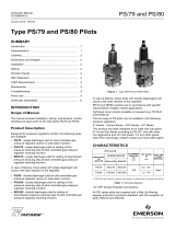
Figure 1. Types PSA/79 and PSA/80 Pilots
Introduction
Scope of the Manual
This manual provides installation, startup,
maintenance, troubleshooting and spare parts for
the pilot series PSA/79 and PSA/80.
Product Description
Designed for pressure regulators control, the following
types are available:
• Type PSA/79 – single diaphragm pilot for pilot
controlled gas pressure regulator (active or wide-
open monitor)
• Type PSOA/79 – single diaphragm pilot for setting
of first pressure reducing step of pilot controlled gas
pressure regulator (working monitor)
• Type REOA/79 – single diaphragm pilot for setting of
downstream pressure reducing step of pilot controlled
gas pressure regulator (working monitor) In case of
failures, these pilots with single diaphragm will cause a
fail open reaction of the regulator.
• Type PSA/80 – double diaphragm pilot for pilot
controlled gas pressure regulator (active or
wide-open monitor)
• Type PSOA/80 – double diaphragm pilot for setting
of first pressure reducing step of pilot controlled gas
pressure regulator (working monitor)
• Type REOA/80 – double diaphragm pilot for setting of
downstream pressure reducing step of pilot controlled
gas pressure regulator (working monitor)

A
B
Types PSA/79 and PSA/80 Pilots
2
Asia Pacic Only
Characteristics
Table 1. Technical Features
Labelling
Figure 2. Label for Types PSA/79 and PSA/80 Series
All PSA Series pilots are supplied with a lter (5μ ltering degree) and built-in pressure stabilizer, except for pilots
Types PSOA/79 and PSOA/80.
APPLICATION
ALLOWABLE
PRESSURE PS, bar SET RANGE Wd, bar BODY AND COVER
MATERIAL
Regulator or Monitor
Working Monitor
Regulator Monitor
Type PSA/79 Type PSOA/79 Type REOA/79
100
0.5-40*
Steel
Type PSA/80 Type PSOA/80 Type REOA/80 1.5-40*
(*) Types PSA/79-AP and PSA/80-AP versions are available on request with a set range up to 65 bar.
Note 1: See “Characteristics”
Note 2: Year of Manufacture
Note 3: Class 1: -10° to 60°C
Class 2: -20° to 60°C
Note 4: See “Characteristics”
Dimensions and Weights
Table 2. Dimensions (mm) and weights (kg)
TYPE PSA/79
FULL RANGE
TYPE PSA/80
FULL RANGE
A 90 90
B 265 290
Weight 8 9
Figure 3. Types PSA/79 and PSA/80 Dimensions

Types PSA/79 and PSA/80 Pilots
3
Asia Pacic Only
In case of failures, these pilots with double diaphragms
will cause a fail close reaction of the regulator.
Tightness cover version available on request
(e.g. Types PSA/79-P and PSA/80-P).
The full range of PSA pilots can be installed in the
following pressure regulators:
FLA Series - Cronos Series - EZH Series - Type 971
This product has been designed to be used with fuel
gases of rst and second family according to EN 437,
and with other non-aggressive and non-fuel gases. For
any other gases, other than natural gas, please contact
your local sales agent.
Installation
1. Check that data on the pilot’s plate are compatible
with actual working conditions.
2. Install in accordance with regulator
instruction manual.
Startup
See the set-up and pilot adjustment instructions
applying to the equipment where the pilot is tted.
Periodic Checks
Slowly close the outlet slam-shut and check line
pressure between it and regulator.
A slight increase in pressure should be detected: this
results from overload due to closing, and is followed
by pressure stabilization. If outlet pressure continues
to rise, then seal is defective. Check if leak is coming
from regulator or pilot, and service.
SEP Statement
Emerson Process Management Regulator
Technologies, Inc. declares this product conforms to
Pressure Equipment Directive.
Article 3 section 3 and was designed and
manufactured in accordance with sound engineering
practice (SEP).
Per Article 3 section 3, this “SEP” product must not
bear the CE marking.
ATEX Requirements
▲ WARNING
If the provisions of EN 12186 and
EN 12279, national regulations,
if any, and specic manufacturer
recommendations are not put into
practice before installation and if purge
by inert gas is not carried out before
equipment’s start-up and shut-down
operations, a potential external
and internal explosive atmosphere
can be present in equipment and
gas pressure regulating/measuring
stations installations.
If a presence of foreign material in the pipelines is
foreseen and purge by inert gas is not carried out,
the following procedure is recommended to avoid any
possible external ignition source inside the equipment
due to mechanical generated sparks:
• Drainage to safe area via drain lines of foreign
materials, if any, by inflow of fuel gas with low
velocity in the pipe-work (5 m/sec)
In any case,
• Provisions of Directive 1999/92/EC and 89/655/EC
shall be enforced by gas pressure regulating/
measuring station/installation’s end user
• With a view to preventing and providing protection
against explosions, technical and/or organizational
measures appropriate to the nature of the operation
shall be taken (e.g.: filling/exhausting of fuel
gas of internal volume of the isolated part/entire
installation with vent lines to safe area - 7.5.2 of
EN 12186 and 7.4 of EN 12279; monitoring of
settings with further exhaust of fuel gas to safe
area; connection of isolated part/entire installation
to downstream pipeline)
• Provision in 9.3 of EN 12186 and 12279 shall be
enforced by pressure regulating/measuring station/
installation’s end user
• External tightness test shall be carried out after
each reassembly at installation site using testing
pressure in accordance with national rules
• Periodical check/maintenance for surveillance shall
be carried out complying with national regulations,
if any, and specific manufacturer recommendations.
Maintenance
△ CAUTION
Servicing should be carried out by
qualied, skilled personnel only. For
further information, please contact our
Technical Support Representatives or
our authorized dealers.
Before servicing, cut o regulator inlet and outlet and
release any trapped pressurized gas. Use suds to
check that there are no leaks.

Types PSA/79 and PSA/80 Pilots
4
Asia Pacic Only
Replacing Filter
1. Remove the screws (key 41), cover (key 59), and
replace felt (key 61). Reassemble by reversing the
above sequence.
Replacing Stabilizer Diaphragm and
Seal Pad
1. Remove screws (key 41), cover (key 64), spring
(key 47) and diaphragm assembly (keys 48,
49, 50, 51, 52 and 53). Replace diaphragm
if necessary.
2. Unscrew seat (key 54) and replace pad
holder (key 56).
3. Reassemble by reversing the above sequence,
make sure not to “pinch” O-rings (key 55).
Replacing Valve Seal Pads
1. Remove plug (key 27) and seat (key 30). Slide
out spring (key 32), pad holder unit (key 34) and
forked stem (key 35).
2. Replace pad holder (key 34) and O-ring (key 37).
3. Reassemble by reversing above sequence.
General Maintenance
1. Completely release spring (key 5) by turning the
adjusting screw (key 1) counterclockwise.
2. Remove screws (key 7) and cover (key 4).
3. Keep plate (key 9 or 75 for the AP version)
blocked with a box wrench, unscrew nut (key 6).
This must be done exactly as described to prevent
damage to or breaking of safety valve (key 20).
4. Unscrew plate (key 9 or 75 for the AP version)
from stem (key 13) remove parts (keys 10, 11 and
12 or 76, 78, 10, 77 and 12 for the AP version).
5. For Type PSA/80 and Type PSA/80-AP version:
Unscrew plate (key 9 or 75 for the AP version)
from stem (key 13) remove parts (keys 10, 68, 69,
11 and 12 or 76, 78, 68, 69, 10, 77 and 12 for the
AP version).
6. Slide off split pin (key 40). Remove locknut
(key 16) with appropriate wrench and slide out
parts (keys 17, 18, 19 and 20). Make sure that the
surface of seat (key 26) which is sealed by pad
(key 21) is in proper condition.
7. Replace diaphragms (key 10) and all seals.
8. Proceed as directed in the replacement of
filter, stabilizer diaphragm, seal pad, and valve
seal pads.
Reassembly
Lubricate the static O-rings with a thin layer of
heavy-duty lubricating paste, be very careful not to
damage the O-rings when reassembling. No other
pilot parts are to be lubricated. Reassemble parts by
reversing the above steps. As you proceed, make sure
that parts move freely and without friction. In addition:
1. Once lever (key 39) and stem (key 13) have been
mounted, check that, with stem (key 13) against
body (key 25), clearance between forked stem
(key 35) and registered (A) of lever (key 39) is 0.2
to 0.3 mm. If not, use register to correct.
△ CAUTION
The above clearance can be checked by
gently pulling stem (key 13) upward. Use
the proper tool to make sure that the top
plate (key 9) is on the same plane as that
supporting the diaphragm (key 10) in the
body (key 25).
2. Mount diaphragm (key 10) and screw on plate
(key 9), first by hand then with box wrench,
(always holding upper diaphragm (key 10) firmly in
place) in order to avoid damage to stem (key 13)
and levers below.
3. Holding plate (key 9) firmly in place with box
wrench, tighten nut (key 6).
4. Before remounting cover (key 4), center
diaphragm as follows:
• Mark a reference point (with pencil) on the
diaphragm; turn it to the right without forcing and
mark another reference on body.
• Now turn diaphragm to the left and mark a
further reference.
• Position the diaphragm mark midway between
the two marks on the body.
5. Tighten all screws uniformly to ensure
proper sealing.
△ CAUTION
The pilot has a wide range of
self-adjustment values. However, given
actual operating conditions, it may
necessary to assist it at times by nding
the best setting of register/pin screw
(key 29) or the most suitable calibration
jet (key 15).

Types PSA/79 and PSA/80 Pilots
5
Asia Pacic Only
Parts List
Type PSA/79 (See Figure 4)
Key Description
1 Adjusting screw
2 Nut
3 Spring holder
4 Cover
5 Spring
6 Nut
7 Screw
8 Washer
9 Plate
10* Diaphragm
11 Plate
12* O-ring
13 Stem
14* O-ring
15* Jet
16 Locking nut
17* “GACO” Ring
18 Thrust bearing
19 Spring
20 Safety valve
21* Pad
22* O-ring
23* O-ring
24 Plug
25 Body
26 Seat
Type PSA/80
Key Description
66 Elbow Fitting
67 Screw
68 Middle ange
69 Hub
Types REOA/79 and REOA/80 Only
Key Description
15 Plug
Types PSA/79-AP and PSA/80-AP Only
Key Description
75 Plate
76 Spacer
77 Plate
78* O-ring
79 Spring holder
Rubber parts marked with (*) are supplied in the “spare parts kit”, recommended as stock.
To order the kit it is necessary to communicate to us the type of the pilot and its serial number.
Troubleshooting
SYMPTOMS CAUSE ACTIONS
Desired set point is not reached
Calibration spring (key 5) is too weak Check the springs catalog and replace it
with a stronger one
Leaks from pilot connections Check pilot feed connections
and proper gas ow feeding
Outlet pressure drops well below set point
Filter (key 61) is clogged preventing
proper through-ow of gas Clean or replace it
Pad holder (key 56) is swollen
preventing proper feed ow To be replaced
Pad holder (key 34) is swollen
preventing proper feed ow To be replaced
Outlet pressure increases over set point
Faulty sealing of pad holder (key 56) To be replaced
Faulty sealing of pad holder (key 34) To be replaced
Slow response to changes in gas demand
Insucient ow rate of valve seat (key 30) Increase ow by means of register/pin screw (key 29)
Overly large calibration jet (key 15)
(only for Types PSA/79 and PSA/80) To be replaced with a smaller one
Overly rapid response to changes in
gas demand, i.e. Hunting
Excessive ow rate of valve seat (key 30) Reduce ow by means of a pin screw (key 29)
Calibration jet (key15) is too small
(only for Types PSA/79 and PSA/80) To be replaced with a larger one
Not proper internal parts assembly Check clearance between lever (key 39)
and forked stem (key 35)
Gas continually escaping from relief (S) Defective seal of pad (key 21) To be replaced
The outlet pressure is not
within the usual values
Diaphragms (key 10) are damaged Replace diaphragms (key 10) that show signs of wear
Upper diaphragm (key 10) is damaged If gas escapes from silencer (key 45), replace
upper diaphragm (key 10)
Table 3. Troubleshooting for Types PSA/79 and PSA/80 Pilots

C
S
R
V
M
C
A
A
B B
1
2
3
4
5
6
7
8
9
10
11
12
13
14
15
16
17
18
19
202324212226272829
30
31
32
33
34
35
36
37
38
39
40
65
45
43
46
43
44
414241 42
62 63 62 64
47
48
49
50
515253545556575859
60
61
14
15
25
65
A
LM/1346
Types PSA/79 and PSA/80 Pilots
6
Asia Pacic Only
Schematic Assemblies
Table 4. Types PSA/79 and PSA/80 Pilots Connections
CODE CONNECTIONS
MUpstream of the regulator
R To the regulator (loading pressure)
S Downstream or safe area
V Downstream of the regulator
Figure 4. Types PSA/79 and PSA/80 Series Detailed Pilots Assemblies
SECTION A-A
SECTION B-B
TYPES REOA/79 AND
REOA/80 DETAIL
TYPE PSA/79
SECTION C-C

62
63
64
62
63
64
52
73
1
70
71
4
72
75
77
76
78
7
79
75
77
76
78
7
68
69
79
7
13
69
68
6667
LM/1346
Types PSA/79 and PSA/80 Pilots
7
Asia Pacic Only
Figure 4. Types PSA/79 and PSA/80 Series Detailed Pilots Assemblies (continued)
TYPES PSA/79-P AND PSA/80-P TYPE PSA/80
TYPE PSA/79-AP TYPE PSA/80-AP
TYPES REOA79 AND REOA/80 TYPES PSOA/79 AND PSOA/80

Types PSA/79 and PSA/80 Pilots
Asia Pacic Only
Facebook.com/EmersonAutomationSolutions
LinkedIn.com/company/emerson-automation-solutions
Twitter.com/emr_automation
Emerson Automation Solutions
Tartarini-NaturalGas.com
D104256X012 © 2019, 2021 Emerson Process Management Regulator
Technologies, Inc. All rights reserved. 09/21.
The Emerson logo is a trademark and service mark of Emerson
Electric Co. All other marks are the property of their prospective owners.
Tartarini™ is a mark owned by one of the companies in the Emerson
Automation Solutions business unit of Emerson Electric Co.
The contents of this publication are presented for informational purposes
only, and while every eort has been made to ensure their accuracy,
they are not to be construed as warranties or guarantees, express or
implied, regarding the products or services described herein or their
use or applicability. All sales are governed by our terms and conditions,
which are available upon request. We reserve the right to modify or
improve the designs or specications of such products at any time
without notice.
Emerson Process Management Regulator Technologies, Inc does not
assume responsibility for the selection, use or maintenance of any
product. Responsibility for proper selection, use and maintenance of any
Emerson Process Management Regulator Technologies, Inc. product
remains solely with the purchaser.
Americas
McKinney, Texas 75070 USA
T +1 800 558 5853
+1 972 548 3574
Europe
Bologna 40013, Italy
T +39 051 419 0611
Asia Pacic
Singapore 128461, Singapore
T +65 6777 8211
Middle East and Africa
Dubai, United Arab Emirates
T +971 4 811 8100
Emerson Process Management s.r.l.
Emerson Automation Solutions - Stabilimento di/Site of: Castel Maggiore - Bologna
Sede Legale/Legal Entity: Piazza Meda 5, 20121 Milano, Italy
Sede Amministrativa/Administrative Headquarters: OMT Tartarini, Via Clodoveo Bonazzi 43,
40013 Castel Maggiore (Bologna), Italy
C.F. - P.I. e R.I. di MI 13186130152 - REA di MI/n.1622916
Direz. e Coord. (art. 2497 bis CC): EMERSON ELECTRIC CO. St. Louis (USA) Socio Unico
/
