Hobart 2912PS ML-104833 User manual

Category
Knives
Type
User manual

This manual is also suitable for

The Hobart 2912PS ML-104833 automatic slicer with portion scale is a versatile kitchen appliance designed for precise and efficient slicing of various food items. It features a poly-V belt driven knife for smooth and accurate slicing, and an interlock switch to prevent continuous operation of the knife motor when the index knob is below "0". The carriage interlock ensures that the gauge plate cannot be opened if the carriage unit is not installed, enhancing safety. Additionally, the slicer boasts a portion scale with weight and count display, allowing for precise portion control.

The Hobart 2912PS ML-104833 automatic slicer with portion scale is a versatile kitchen appliance designed for precise and efficient slicing of various food items. It features a poly-V belt driven knife for smooth and accurate slicing, and an interlock switch to prevent continuous operation of the knife motor when the index knob is below "0". The carriage interlock ensures that the gauge plate cannot be opened if the carriage unit is not installed, enhancing safety. Additionally, the slicer boasts a portion scale with weight and count display, allowing for precise portion control.

A product of HOBART CORPORATION TROY, OHIO 45374
Form F-24653 (June 1999)
- NOTICE -
This Manual is prepared for the use of trained Hobart Service
Technicians and should not be used by those not properly
qualified. If you have attended a Hobart Service School for this
product, you may be qualified to perform all the procedures
described in this manual.
This manual is not intended to be all encompassing. If you have
not attended a Hobart Service School for this product, you should
read, in its entirety, the repair procedure you wish to perform to
determine if you have the necessary tools, instruments and skills
required to perform the procedure. Procedures for which you do
not have the necessary tools, instruments and skills should be
performed by a trained Hobart Service Technician.
Reproduction or other use of this Manual, without the express
written consent of Hobart Corporation, is prohibited.
SERVICE MANUAL
SUPPLEMENT
MODEL 2912PS
AUTOMATIC SLICER
WITH PORTION SCALE
ML-104833
This Service Manual Supplement should be used
with Service Manual Form 24569 02-98.
MODEL 2912PS SLICER GENERAL
Page 2 of 24
TABLE OF CONTENTS
GENERAL............................................................................. 3
Introduction ........................................................................ 3
Model ......................................................................... 3
Features....................................................................... 3
Operation.......................................................................... 3
Specifications ...................................................................... 3
Electrical ...................................................................... 3
Scale Capacity .................................................................. 3
Tools ............................................................................. 3
Special........................................................................ 3
REMOVAL AND REPLACEMENT OF PARTS ................................................. 4
Upper Base and Automatic Base Component Access ........................................ 4
Scale Keypad or Bezel ................................................................ 5
Slice Switch (3LS) ................................................................... 6
Slicer Control Board.................................................................. 6
Motor Control Board.................................................................. 6
Scale Board........................................................................ 6
Loadcell ........................................................................... 7
SERVICE PROCEDURES AND ADJUSTMENTS ............................................... 8
Loadcell Stop Plate Adjustment ......................................................... 8
Platter Stop Adjustment............................................................... 8
Scale Board Test ................................................................... 9
Service Programming ............................................................... 10
Programming Entry ............................................................. 10
Programming Exit .............................................................. 10
Main Menu .................................................................... 10
Calibration of Loadcell (Cal) (Lbs. Or Kgs.) ............................................ 11
Configuration Programming (CnF) .................................................. 12
The Motor Control Board and Automatic Drive Motor Test ................................... 14
Testing the Slicer Control Board ....................................................... 14
Automatic Low/high Speed Adjustment .................................................. 15
Carriage Transport Assembly Adjustments ................................................ 16
Interlock Switch Adjustment........................................................... 17
Carriage Tray Assembly Adjustments ................................................... 18
Scale Keypad and Cable Test ......................................................... 19
ELECTRICAL OPERATION .............................................................. 20
Component Function ................................................................ 20
Manual Sequence of Operation ........................................................ 20
Automatic Sequence of Operation ..................................................... 21
Scale Board Information ............................................................. 22
Wiring Diagram .................................................................... 23
TROUBLESHOOTING .................................................................. 24
© HOBART CORPORATION 1999
MODEL 2912PS SLICER GENERAL
Page 3 of 24
GENERAL
INTRODUCTION
NOTE:
This is a supplement to Models 2612, 2712,
2812 and 2912 Service Manual F-24569 02-98.
Model
2912PS - Automatic Slicer with Portion Scale that
displays the weight or slice count. Six preset values
can be programmed with weight or slice count.
The scale display can Tare to indicate Net Weight
but is
NOT LEGAL FOR TRADE.
Features
Knife Home start
- The knife motor will not start
unless the carriage unit is at the indexing knob end
of the slicer. (Home Position)
Poly-V Belt driven knife.
Interlock Switch - Prevents the continuous operation
of the knife motor when the index knob is below0".
Carriage interlock
- The gauge plate cannot be
opened if the carriage unit is not installed onto the
unit.
No voltage release
- Requires the slicer to be
manually re-started after a power interruption.
Portion Scale
- Portion control with weight and count
with display.
Carriage Tray Assembly with Two Handles
Sharpener Housing Mount, Base and Tray Support
Assembly - They have an anodized finish.
Cleaning
-Lift lever on side.
Automatic Home Return
- When user defined preset
weight or slice count is reached, carriage will stop at
the home position.
Carriage Speeds (Automatic Mode)
- Six carriage
speeds.
Carriage Home Start
- The automatic drive motor
will not start unless the carriage unit is at the
operator end of the slicer (home position).
Automatic shut-off
- If enabled, slicer will turn off (in
manual mode only) if a keystroke or full stroke of
the carriage has not been made within a 10 second
interval.
OPERATION
Refer to Instruction Manual F-34214
SPECIFICATIONS
Electrical
120/60/1
Scale Capacity
Capacity Increments Max.
Tare
Re-zero at
Power Up
Rezero
Key
LB. 6 .01 2.00 ± 0.30 ± 0.11
OZ. 96.5 .5 32 4.5 2
KG. 3 0.010 1.000 ± 0.150 ± 0.060
GM. 3030 10 1000 150 60
TOOLS
NOTE:
The special tools listed below are required in
addition to those tools shown in Service Manual F-
24569 02-98
Special
Set of certified pound test weights TL No. 77617-1.
Set of certified kg. test weights TL No. 77617-26.
Trimpot Tool Part Number 539123 for adjustment of
automatic low/high speeds.
Loctite Number 242, Part Number 520228, used on
automatic motor mounting screws.
In. lb. Torque Wrench.
Combination Square
RTV 732 Dow clear silicone, Part Number 513886-3
for sealing scale keypad to bezel.
MODEL 2912PS SLICER REMOVAL AND REPLACEMENT OF PARTS
Page 4 of 24
REMOVAL AND REPLACEMENT OF PARTS
NOTE:
Many procedures state the carriage transport assembly should be moved to home position. The carriage
transport assembly is in home position when it is pulled all the way to the operator end of the slicer.
CAUTION: Certain components in this system are subject to damage due to electrostatic discharge. A
Field Service Grounding kit is available to prevent this damage. The Field Service Grounding kit must be
used when any electronic boards or cables are handled.
UPPER BASE AND AUTOMATIC
BASE COMPONENT ACCESS
WARNING:
UNPLUG UNIT BEFORE SERVICING.
1. Turn index knob to below 0 position (fully
clockwise).
2. Move carriage transport assembly to home
position.
3. Remove CARRIAGE TRAY ASSEMBLY, as
outlined in the service manual.
4. Remove KNIFE SHARPENER, as outlined in
the service manual.
5. Remove platter and platter support assembly
by lifting.
6. Turn the slicer up and rest it on the sharpener
side of the automatic base.
7. For components in the automatic base, under
the bottom cover, unscrew lower feet, remove
ten screws around outline of cover and pull
cover from automatic base.
8. For components in the automatic base, on the
electrical cover assembly, remove eight screws
and carefully pull assembly outward to access
wiring connections.
9. For components in the upper base, perform
Step 7 and disconnect loadcell.
A. Unscrew the upper right hand foot.
B. Remove four screws to free automatic
base from upper base and position
automatic base as shown.
MODEL 2912PS SLICER REMOVAL AND REPLACEMENT OF PARTS
Page 5 of 24
C. For components behind the upper
electrical cover, remove five screws.
1) Pull cover on an angle away from the
on/off switch outward and upward for
removal.
10. Reassemble in reverse order.
11. Check unit for proper operation.
SCALE KEYPAD OR BEZEL
NOTE:
When replacing the bezel, a new scale
keypad must be installed.
WARNING:
UNPLUG UNIT BEFORE SERVICING.
1. Perform UPPER BASE AND AUTOMATIC
BASE COMPONENT ACCESS, Steps 1-7 and
9-9B as outlined in this supplement.
2. Disconnect motor wires in speed selector
switch cavity and pull them from half grommet.
3. Loosen screw in motor crank link assembly.
NOTE:
When reinstalling, place the motor
crank link nearly flush with the end of the
output shaft, but maintain clearance between
back of link and the automatic base. Tighten
the screw to 90 ± 3 inch pounds.
4. Remove retaining ring where motor drive link
assembly is attached to the main link
assembly.
A. Pull motor crank link/motor drive link
assemblies from main link assembly and
automatic motor shaft.
5. Remove four screws and pull automatic motor
from base.
NOTE:
When installing the
automatic motor mounting screws, use Loctite
No. 242 and torque to 25 ± 3 inch pounds.
6. Remove two screws holding automatic/manual
switch mounting bracket to automatic base and
move out of the way to access slice count
bezel mounting screws.
7. Remove six screws holding bezel and gasket to
automatic base and carefully pull outward to
access keypad cable.
A. Disconnect cable from keypad.
8. Remove six nuts and lockwashers holding
keypad to bezel.
A. Press keypad from bezel using your
hands.
9. Clean RTV from keypad mounting surface of
bezel.
A. Apply RTV 732 Dow clear silicone to
keypad mounting surface.
10. When installing the new keypad, remove
protective paper from over buzzer and backing
from perimeter of keypad.
11. Reassemble in reverse order.
12. Check unit for proper operation.
MODEL 2912PS SLICER REMOVAL AND REPLACEMENT OF PARTS
Page 6 of 24
SLICE SWITCH (3LS)
WARNING:
UNPLUG UNIT BEFORE SERVICING.
1. Perform UPPER BASE AND AUTOMATIC
BASE COMPONENT ACCESS Steps 1-7 and
9-9C 1), as outlined in this supplement.
2. Remove three screws to free switch bracket
from base.
3. Remove two screws, nuts and lockwashers to
free switch from switch bracket.
4. Remove P clamp.
5. Note location of switch wires, cut wire tie(s) and
disconnect wires.
6. Reassemble in reverse order.
7. Check unit for proper operation.
SLICER CONTROL BOARD
WARNING
: UNPLUG UNIT BEFORE SERVICING.
1. Perform UPPER BASE AND AUTOMATIC
BASE COMPONENT ACCESS, Steps 1-6 and
8 as outlined in this supplement.
2. Disconnect J1, J2 and J3 from board.
3. Remove six nuts and washers. Lift board from
standoffs.
4. Reassemble in reverse order.
5. Check unit for proper operation.
MOTOR CONTROL BOARD
WARNING:
UNPLUG UNIT BEFORE SERVICING.
1. Perform UPPER BASE AND AUTOMATIC
BASE COMPONENT ACCESS, Steps 1-8 as
outlined in this supplement.
2. Place the connected electrical cover assembly
in front of the automatic base.
3. Note the location of the wires and disconnect
them.
4. Remove the mounting hardware to free the
board from the electrical cover assembly.
5. Reinstall the board and connect the wires.
6. Perform AUTOMATIC LOW/HIGH SPEED
ADJUSTMENT, as outlined in this supplement,
beginning at Step 3.
SCALE BOARD
WARNING:
UNPLUG UNIT BEFORE SERVICING.
1. Remove SLICER CONTROL BOARD, as
outlined in this supplement.
2. Disconnect J2, J3 and J5 from board.
MODEL 2912PS SLICER REMOVAL AND REPLACEMENT OF PARTS
Page 7 of 24
3. Remove three standoffs, three nuts and
washers.
A. Lift board from standoffs.
B. Remove two standoffs from board
transformer and save.
NOTE:
Check that the voltage selector switch
(SW3) on the replacement board is set for 115 volts.
4. Reassemble in reverse order.
5. Calibrate the loadcell as outlined in SERVICE
PROCEDURES AND ADJUSTMENTS ,
CALIBRATION OF LOADCELL, this
supplement.
6. Check unit for proper operation.
LOADCELL
WARNING:
UNPLUG UNIT BEFORE SERVICING.
1. Perform UPPER BASE AND AUTOMATIC
BASE COMPONENT ACCESS, Steps 1-7 and
9-9C 1), as outlined in this supplement.
2. Remove the two screws and lockwashers
holding loadcell to the base.
3. The directional arrow on the loadcell must point
down, away from the slicer base. If the
directional arrow is not on the loadcell, install
with the strain gauge toward the slicer base.
Attach to the base using two screws and
lockwashers. Finger tighten screws.
4. Place the platter support assembly into the
humpnut/loadcell hole in the base.
A. Adjust the position of the loadcell until the
platter support assembly is centered in the
humpnut hole.
B. While holding the loadcell in place tighten
the mounting screws to 50-65 in.lbs.
5. Adjust the loadcell stop plate as outlined in
SERVICE PROCEDURES AND
ADJUSTMENTS , LOADCELL STOP PLATE
ADJUSTMENT, this supplement.
6. Reassemble in reverse order, step 1 of this
procedure.
7. Calibrate loadcell as outlined in SERVICE
PROCEDURES AND ADJUSTMENTS ,
CALIBRATION OF LOADCELL, this
supplement.
8. Check unit for proper operation.
MODEL 2912PS SLICER SERVICE PROCEDURES AND ADJUSTMENTS
Page 8 of 24
SERVICE PROCEDURES AND ADJUSTMENTS
WARNING:
CERTAIN PROCEDURES IN THIS SECTION REQUIRE ELECTRICAL TEST OR
MEASUREMENTS WHILE POWER IS APPLIED TO THE MACHINE. EXERCISE EXTREME CAUTION AT ALL
TIMES. IF TEST POINTS ARE NOT EASILY ACCESSIBLE, DISCONNECT POWER, ATTACH TEST
EQUIPMENT AND REAPPLY POWER TO TEST.
CAUTION: Certain components in this system are subject to damage due to electrostatic discharge. A
Field Service Grounding kit is available to prevent this damage. The Field Service Grounding kit must be
used when any electronic boards or cables are handled.
LOADCELL STOP PLATE
ADJUSTMENT
WARNING:
UNPLUG UNIT BEFORE SERVICING.
1. Access the loadcell by performing UPPER
BASE AND AUTOMATIC BASE COMPONENT
ACCESS, Steps 1-7 and 9-9C 1) as outlined in
this supplement.
2. There should be a .025" to .030" gap between
the loadcell and the top of the loadcell stop
plate with 0" weight on the platter.
3. Add or remove shims until correct.
NOTE:
Only use shims listed in Parts Catalog.
4. Reassemble in reverse order, step 1 of this
procedure.
5. Check the scale for accuracy.
PLATTER STOP ADJUSTMENT
1. Plug the slicer in and allow to self-zero.
2. Remove the stainless steel platter, but leave
the platter support assembly in place.
3. Place 8 lbs. (3.6 kg) on one of the corners
where a platter stop screw is located on the
platter support assembly.
4. Remove the RTV on top of the platter stop
screw and turn the screw until it touches the
slicer base. Watch the display for the weight to
decrease, this indicates that the screw is
touching the slicer base.
5. Back the screw out a little at a time, until the
display stops changing.
6. Turn the stop screw 1 turn counterclockwise.
7. Move the 8 lbs. (3.6 kg.) to the other corner
with a platter stop screw and repeat steps 5-8.
8. Remove the weight.
9. Apply RTV to the top of the two screws and
smooth the surface.
10. Install the stainless steel platter on the platter
support assembly.
MODEL 2912PS SLICER SERVICE PROCEDURES AND ADJUSTMENTS
Page 9 of 24
SCALE BOARD TEST
WARNING:
UNPLUG UNIT BEFORE SERVICING.
1. Determine line voltage to unit.
2. Perform UPPER BASE AND AUTOMATIC BASE COMPONENT ACCESS, Steps 1-8 as outlined in this
supplement.
3. Place the connected electrical cover assembly in front of the automatic base.
4. Plug the unit in.
5. Check for line voltage across J5-1 and J5-5. If incorrect, correct before proceeding.
6. Using TP3 as ground, check for:
+5VDC at TP6; +12VDC at TP4 and -5VDC at TP7.
A. If voltages test correctly, continue to troubleshoot using Troubleshooting in this supplement.
B. If voltages test incorrectly, replace the board.
7. Unplug unit.
8. Perform Step 2 in reverse order.
9. Check unit for proper operation.
MODEL 2912PS SLICER SERVICE PROCEDURES AND ADJUSTMENTS
Page 10 of 24
SERVICE PROGRAMMING
Programming Entry
1. With the slicer plugged in, turned off and the manual/automatic lever in automatic, index knob above O,
pull and release start switch knob. Wait for display.
2. Press and hold mode and keys at the same time for six seconds. Display will show Prog, then display
CAL, CnF or dIAg. The information for service diagnostics (dIAg) has not been developed at this time.
NOTE:
Configuration (CnF) of the slicer must be done prior to calibration (CAL) of the loadcell.
Programming Exit
Exit the service programming mode by pressing the mode key again for two seconds.
Main Menu
Main Menu
Display Key Action (when key pressed) Comments
CAL
(Stands for
Calibration)
MODE Step to Next Function (CnF) Entry to functions
CAL then execute loadcell
calibration
Entry to calibration
MODE PRESSED FOR
TWO SECONDS
Return to normal operation Exit from programming
CnF
(Stands for
Configuration)
UP ARROW CnF, then enter setup function Entry to setup
programming
MODE Step to Next Function (dIAg)
MODE PRESSED FOR
TWO SECONDS
Return to normal operation Exit from programming
dIAg
(Stands for Service
Diagnostics)
XXXX XXXX XXXX
MODE SEr Displayed then back to CAL
Display
MODE PRESSED FOR
TWO SECONDS
Return to normal operation Exit from programming
MODEL 2912PS SLICER SERVICE PROCEDURES AND ADJUSTMENTS
Page 11 of 24
Calibration of Loadcell (Cal) (Lbs. Or Kgs.)
NOTE:
If a displayed number does not fall within the range, the loadcell cannot be calibrated until the problem is
corrected.
NOTE:
Remove all weight from scale platter before calibration of loadcell.
Calibration of Loadcell key
Display Key Comments
0.00 MODE
8.00 lbs
or
3.600 kgs
MODE Place weight (8.00 lbs. Or 3.6 kgs.) on platter.
0.00 MODE Remove all weight from the scale platter.
XXXX MODE Range: 0E00 - 1200 (lbs. or kgs.).
1.00 lb
or
1.000 kg
MODE Place weight (1 lb. or 1 kg.) on the platter.
XXXX MODE Range:
1F00 - 2100 (lbs.)
4500 - 47FF (kgs.)
6.00 lbs.
or
3.2 kgs
MODE Place weight (6.0 lbs. or 3.2 kgs.) on the scale platter.
XXXX MODE Range:
1F00 - 2100 (lbs.)
4500 - 47FF (kgs.)
XXXX MODE Range:
1F00 - 2100 (lbs.)
4500 - 47FF (kgs.)
0.00 MODE Remove all weight from the scale platter.
NOTE:
All calibration parameters are stored at this point.
XXXX MODE Range: 0E00-1200
donE MODE Test complete. Return to main menu.
MODE PRESSED
FOR TWO
SECONDS
Return to normal operation.
NOTE:
Do the following to ensure proper operation of the scale.
1. Perform an increasing and decreasing load test.
2. Perform an overtravel load test by placing 6 lbs. on one of the corners
indicated by a X and verifying that the platter stop does not touch the
slicer base. Repeat for the other corner.
MODEL 2912PS SLICER SERVICE PROCEDURES AND ADJUSTMENTS
Page 12 of 24
Configuration Programming (CnF)
NOTE:
The following is a listing of the programmable features and the factory defaults.
Programmable Features
Weight unit
Domestic: LB. (Default) or ounces.
International: KG (default) or grams.
(All units can select the four units described above (at the Factory level), however, there will be two
different display options. One for kg/g, the other for lb./ounces).
Motion indicator On/Off.
On: Dash out the display while in motion.
Off: Continue showing weight.
Auto-zero: ENABLE/DISABLE.
MODEL 2912PS SLICER SERVICE PROCEDURES AND ADJUSTMENTS
Page 13 of 24
Configuration Programming
Display Key Action (when Key pressed) Comments
oE, HI g, Lo g, or Lb UP ARROW Toggle between Lb, oE, HI g and
Lo g weight modes
Default: Factory will set to Lb for
domestic, HI g (KG) for
international.
Select Lb, oE, HI g or
Lo g weight mode. The
OZ/GR or LB/ KG
indicator flashes to
match the display and
indicate the active mode.
MODE Saves setup and goes to the next
step.
no bL
or
bL
UP ARROW Toggle between:
no bL: Do not blank, display data
during motion.
bL: Displays - - - - blank during
motion.
Default: no bL (Do not blank)
Select display data or
blank when the platter is
in motion.
MODE Saves setup and goes to the next
step.
no A0
or
A0
UP ARROW Toggle between:
no AO: Auto-zero OFF
AO: Auto-zero ON
Default: AO (Auto-zero ON)
Select auto-zero mode
(on or off)
MODE Saves setup and goes to the next
step.
donE MODE Flashes Ser, then return to main
menu.
MODE PRESSED
FOR TWO
SECONDS
Return to normal operation.
MODEL 2912PS SLICER SERVICE PROCEDURES AND ADJUSTMENTS
Page 14 of 24
THE MOTOR CONTROL BOARD
AND AUTOMATIC DRIVE
MOTOR TEST
NOTE:
Due to the operating characteristics of the
motor control board, an open circuit or a no load
condition at J6 and J7 may result in voltage
readings which could lead the service technician to
an incorrect conclusion.
WARNING
: UNPLUG UNIT BEFORE SERVICING.
1. Perform UPPER BASE AND AUTOMATIC
BASE COMPONENT ACCESS, Steps 1-8 as
outlined in this supplement.
2. Place the connected electrical cover assembly
in front of the automatic base.
3. Carefully return the slicer to the upright position
taking care to leave clearance between the
automatic base and the electrical cover
assembly.
4. Disconnect the motor wires from J6 and J7 and
continuity check the motor and motor wiring
including the brushes.
A. 4 to 8 ohms is the normal range.
B. Reconnect motor after continuity has been
verified.
5. Check for correct voltage to the slicer.
6. Turn the Index knob above 0".
7. Turn on the Slicer.
8. Place Lever in automatic position.
9. Press and release the SLICE/PAUSE switch.
10. Check for 120 VAC input at J2 and J1 of motor
control board.
A. If incorrect, trace back to find the source
of voltage loss.
B. If voltage is present:
1) Disconnect J3 from motor control
board. The automatic drive motor
should run in low speed.
2) Disconnect J3 and J4, short the
connectors on the board. The motor
should run in high speed.
11. If the motor does not run as stated above,
replace motor control board, and adjust as
outlined in AUTOMATIC LOW/HIGH SPEED
ADJUSTMENT, steps 3 and 5 thru 20 in this
supplement.
TESTING THE SLICER CONTROL
BOARD
WARNING:
UNPLUG UNIT BEFORE SERVICING.
1. Perform steps 1-3 and 5-9 of the THE MOTOR
CONTROL BOARD AND AUTOMATIC DRIVE
MOTOR TEST, as outlined in this supplement.
NOTE:
120 VAC REFERS TO THE HOT SIDE OF
THE LINE VOLTAGE (BLACK WIRE). 2CR-O IS A
CONVENIENT PLACE TO ACCESS NEUTRAL.
2. Check for 120 VAC at slicer control board J3-4,
J3-5, J3-6, J3-7, J3-8, J3-9 and J3-12.
NOTE:
J3-5, 6, 9 and J3-10 are inputs.
3. If voltages are not present, check the circuits
associated with these terminals.
4. If those circuits check OK, replace slicer
control board.
5. Reassemble and check for proper operation.
MODEL 2912PS SLICER SERVICE PROCEDURES AND ADJUSTMENTS
Page 15 of 24
AUTOMATIC LOW/HIGH SPEED
ADJUSTMENT
WARNING:
UNPLUG UNIT BEFORE SERVICING
UNIT.
NOTE:
The speed adjustment should be made with
a cold automatic motor. Use the trimpot tool to
make potentiometer adjustments. After each
potentiometer adjustment on the motor control
board the carriage assembly must cycle three
complete strokes before the accurate adjusted
strokes per minute are displayed. Turn the
potentiometer clockwise for higher number of
strokes, counterclockwise for a lower number.
1. Perform UPPER BASE AND AUTOMATIC
BASE COMPONENT ACCESS, Steps 1-8 as
outlined in this supplement.
2. Place the connected electrical cover assembly
in front of the automatic base.
3. Reinstall feet.
4. Carefully return the slicer to the upright position
taking care to leave clearance between the
automatic base and the electrical cover
assembly.
5. Reinstall the CARRIAGE TRAY ASSEMBLY,
as outlined in the service manual.
6. Plug unit in.
7. Turn unit on and place in automatic.
8. Press tortoise key until only one LED is lit (low
speed).
9. Press slice/pause switch. If motor is not
running, adjust low speed adjustment
potentiometer clockwise until automatic motor
runs.
10. Press and hold tortoise key for two seconds to
access carriage strokes per minute mode (all
LEDS off).
11. Adjust low speed potentiometer until 16 strokes
+ or - 2 is displayed.
12. Press hare key until carriage speed is on high
(all speed LEDS lit).
13. Adjust high speed potentiometer until 52 ± 1 is
displayed.
14. Press slice/pause switch to halt carriage at
home.
15. Place unit in manual and turn off.
16. Unplug unit.
17. Remove CARRIAGE TRAY ASSEMBLY, as
outlined in the service manual.
18. Turn the slicer up and rest it on the sharpener
side of the automatic base.
19. Perform Step 1 of this procedure in reverse
order.
20. Check unit for proper operation.
MODEL 2912PS SLICER SERVICE PROCEDURES AND ADJUSTMENTS
Page 16 of 24
CARRIAGE TRANSPORT
ASSEMBLY ADJUSTMENTS
The carriage transport assembly is adjusted properly
when:
1. The interlock bar clears the bottom
of the
pivoting interlock plate assembly by .005" to
.020" when in the locked position.
2. The interlock bar clears the edge
of the lockout
bar during carriage movement by a maximum
of .030" but with no interference.
3. The overturn screw is within .005" maximum,
but no interference with the transport roller bar.
TO ADJUST:
1. These adjustments should be performed in the
following order and all should be checked
anytime an adjustment is made.
2.
WARNING:
UNPLUG UNIT BEFORE
SERVICING.
3. Perform UPPER BASE AND AUTOMATIC
BASE COMPONENT ACCESS, steps 1-6 and
9-9B as outlined in this supplement.
4. Loosen the four screws holding the lockout bar
to the base.
A. Lift the lockout bar upward to its highest
position and tighten the four screws.
5. To adjust the interlock bar clearance:
A. Position the carriage transport assembly in
the home and locked (tilted) position.
B. Loosen the allen screw holding the roller
bearing assembly to the carriage transport
assembly using the special Allen wrench.
C. Turn the adjusting screw until the interlock
bar clears the bottom
of the pivoting
interlock plate assembly by .005" to .020"
and tighten the allen screw.
6. To adjust the interlock bar clearance:
A. Remove two screws holding transport
cover to transport.
B. Install CARRIAGE TRAY ASSEMBLY(as
outlined in the service manual) which
moves the interlock bar to the operating
position and move the carriage transport
assembly away from the home position.
C. Turn the interlock bar shaft until the
interlock bar clearance to the edge
of the
lockout bar is .030" maximum but with no
interference.
D. Remove CARRIAGE TRAY ASSEMBLY
(as outlined in the service manual).
E. Reinstall transport cover to transport.
MODEL 2912PS SLICER SERVICE PROCEDURES AND ADJUSTMENTS
Page 17 of 24
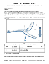
To adjust the overturn screw within .005" maximum,
but with no interference with the transport roller bar,
loosen the locknut and turn the overturn screw to
obtain the proper clearance.
F. Tighten the locknut.
7. Using key plate tool move the carriage
transport assembly out of the interlocked
position and move it back and forth its full
travel, placing it in and out of the interlocked
position, checking for proper movement and
interlocking.
8. Reassemble in reverse order, step 3.
9. Check CARRIAGE TRAY ASSEMBLY
ADJUSTMENTS as outlined in this
supplement.
10. Check unit for proper operation.
INTERLOCK SWITCH
ADJUSTMENT
NOTE:
The slicer must shut off with the carriage
tray assembly at the home position and tilted
outward.
To test, place the carriage tray assembly at the
home position and tilt the carriage tray outward.
Put a slight counterclockwise pressure on the index
knob (attempting to open gauge plate) and pull the
ON-OFF-START switch knob to the Start position.
Release the switch to the Run position while still
applying pressure to index knob. If the slicer
continues to run, release the pressure on the index
knob.
The slicer must shut off.
WARNING:
CERTAIN PROCEDURES IN THIS
SECTION REQUIRE ELECTRICAL TESTS OR
MEASUREMENTS WHILE POWER IS APPLIED
TO THE MACHINE. EXERCISE EXTREME
CAUTION AT ALL TIMES. IF TEST POINTS ARE
NOT EASILY ACCESSIBLE, DISCONNECT
POWER, ATTACH TEST EQUIPMENT AND
REAPPLY POWER TO TEST.
TO ADJUST:
1. Perform UPPER BASE AND AUTOMATIC
BASE COMPONENT ACCESS, steps 1-6 and
9-9B as outlined in this supplement.
2. Check CARRIAGE TRANSPORT ASSEMBLY
ADJUSTMENTS as outlined in this
supplement. Adjust as necessary.
3. With the index knob fully clockwise and
released, back off the switch actuating screw in
the interlock plate assembly and verify the
screw has a locking patch on it. If not, Loctite
No. 242, part No. 520228 must be applied to
the threads prior to adjustment.
4. Move the transport assembly away from home
position.
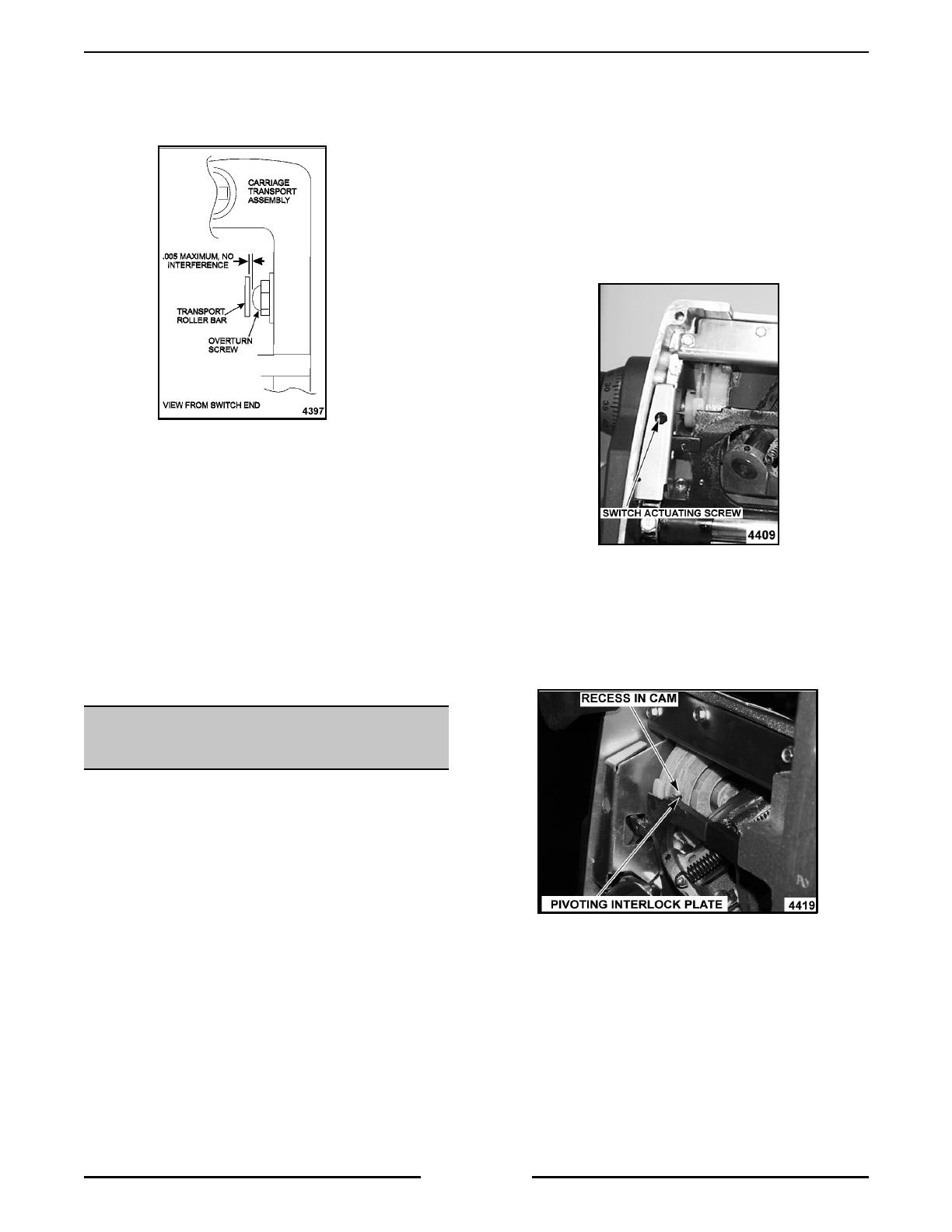
5. Slowly turn the switch actuating screw
clockwise until the pivoting interlock plate just
begins to lift from the recess in the cam.
A. Slowly turn the actuating screw
counterclockwise until the interlock plate is
bottomed into the recess in the cam.
6. Test the adjustment as outlined at the
beginning of this procedure.
7. Check that turning the index knob to 0" or
below 0" shuts the slicer off.
A. If it does not, adjust the GAUGE PLATE
AND INDEXING KNOB as outlined in the
service manual.
B. Unplug slicer.
8. Reassemble in reverse order step 1.
9. Check unit for proper operation.
MODEL 2912PS SLICER SERVICE PROCEDURES AND ADJUSTMENTS
Page 18 of 24
CARRIAGE TRAY ASSEMBLY
ADJUSTMENTS
The carriage tray assembly is adjusted properly
when:
1. the tray is square to the knife edge and,
2. the two adjusting screws in the transport
assembly contact the drive studs in the tray
arm simultaneously and,
3. there is .090" to .125" clearance between
three specific points on the edge of the carriage
tray and the knife.
TO ADJUST:
WARNING:
UNPLUG UNIT BEFORE SERVICING.
1. Check CARRIAGE TRANSPORT ASSEMBLY
ADJUSTMENTS as outlined in this
supplement.
2. Remove the knife cover.
3. Securely attach the carriage tray assembly to
the transport assembly.
4. Check the squareness of the carriage tray to
the knife.
A.
To adjust the squareness:
1) Rotate the adjusting screws in the
transport as needed to square the
arm. Lock in place using the jam
nuts.
2) Verify both screws are touching the
drive studs by inserting a thin piece of
paper between the adjusting screws
and the tray arm drive studs, then
closing the arm against the adjusting
screws. Open the arm, remove the
paper and check it for signs of
contact. Both screws must make
contact with the tray arm drive studs.
5. Check the gap between the tray edge and the
knife edge by measuring at three points.
A. Move the tray until point 1 (tray V) is
above the knife edge.
Measure the gap
and record the dimension
.
B. Move the tray until point 2 (leading edge
of tray) is above the knife edge.
Measure
the gap and record the dimension
.
C. Move the tray until point 3 (upper tip of
tray wall) is above the knife edge.
Measure the gap and record the
dimension
.
MODEL 2912PS SLICER SERVICE PROCEDURES AND ADJUSTMENTS
Page 19 of 24
6. Confirm that the gap MEASURED IN STEP 5A,
5B, AND 5C at points 1, 2 and 3 are
BETWEEN .090" AND .125".
A.
To adjust the gap:
NOTE:
Anytime the earlier version tray assembly is
split from the tray support, RTV 732 must be
reapplied to seal the two assemblies together.
1) Loosen the four nuts (screws on
earlier units) on the carriage tray.
Apply Loctite 242 to the carriage tray
studs on the newer units.
2) Move the tray to achieve the .090" to
.125" clearance.
3) Torque the four nuts to 80 in. lbs. or
tighten the screws.
4) Recheck the gap after tightening.
SCALE KEYPAD AND CABLE TEST
NOTE:
When an individual keypad button is pressed for a continuity test, a reading of 100 ohms or less is
acceptable.
WARNING:
UNPLUG UNIT BEFORE SERVICING.
1. Perform UPPER BASE AND AUTOMATIC BASE COMPONENT ACCESS steps 1-6 and 8 as outlined in
this supplement.
2. Disconnect cable at J2 on the slicer control board.
3. Place a probe at pin 1 or 3 or 5 on the display cable connector.
4. Test each individual keypad button by pressing and taking a continuity reading at the proper connector pin
number.
NOTE:
When the slice/pause switch is pressed there should be continuity at pins 9 and 10.
5. Reassemble in reverse order step 1.
6. Check unit for proper operation.
MODEL 2912PS SLICER ELECTRICAL OPERATION
Page 20 of 24
ELECTRICAL OPERATION
COMPONENT FUNCTION
Loadcell ......................
Used to measure the weight of the product on the platter.
NOTE:
Works like a group of variable resistors. The resistance varies by
the amount of strain that is put on the loadcell.
Scale Board ................
Takes the signal developed through the loadcell and converts it to a signal
that is displayed. Contains the transformer for converting 115 VAC to
needed voltages.
Scale Keypad................
Indicates weight on the platter, slice count and information in the service
mode. In normal operation, digits will go blank after 5 minutes if not used,
but LED annunciators and decimal point will remain lit. Six LEDS indicate
carriage speed selected.
Slice Switch (3LS) ............
Monitors carriage tray movement for slice count and auto shutoff feature.
Slicer Control Board ............
Monitors conditions and controls operation of components.
Automatic/Manual Switch (3S) . .
Controls mode of operation.
NOTE:
120 VAC REFERS TO THE HOT SIDE OF THE LINE VOLTAGE (BLACK WIRE).
The following examples are based on a model 2912PS, 120/60/1, Wiring Diagram F-34185B.
MANUAL SEQUENCE OF
OPERATION
1. Conditions:
A. Correct voltage is supplied to slicer.
B. Index knob is turned to 0" or above (Carriage Interlock Switch 1LS closed).
C. Carriage Tray Assembly in the home position (Home Start Switch 2LS closed).
D. On/off Switch 1SW in OFF position.
E. Automatic/Manual 2S/3S Switch in manual position (2S contacts C-NC closed).
F. Slicer plugged in 120VAC applied to 1SW-4, J3-10 Slicer Control Board, 1CR-2, 2CR-2 and J5-1 Scale
Board. Neutral applied to J3-11 Slicer Control Board, 1CR-0, 2CR-0, J2 Motor Control Board and J5-5
Scale Board.
2. Operator pulls On-Off switch 1SW to start position. 120VAC applied to J3-9, J3-12, J3-8, J3-7, 1CR
energizes through pin J3-7 on slicer control board.
A. 1PL lights and 1MTR (knife motor) is energized through 1CR-2/4.
3. 1CR locks through 1SW-4/1, 1LS and slicer control board.
4. Display shows slice count or weight, the preset indicator is off and speed LED(S) are lit.
5. Operator releases 1SW, 1SW-2/3 open, 1SW-4/1 stay closed.
6. Operator manually moves carriage transport assembly through one complete forward stroke, passing slice
count switch 3LS.
7. Display increases by one slice count or weight of slice for each complete forward carriage stroke.
8. Operator returns carriage transport assembly to home position.
  • Page 1 1
  • Page 2 2
  • Page 3 3
  • Page 4 4
  • Page 5 5
  • Page 6 6
  • Page 7 7
  • Page 8 8
  • Page 9 9
  • Page 10 10
  • Page 11 11
  • Page 12 12
  • Page 13 13
  • Page 14 14
  • Page 15 15
  • Page 16 16
  • Page 17 17
  • Page 18 18
  • Page 19 19
  • Page 20 20
  • Page 21 21
  • Page 22 22
  • Page 23 23
  • Page 24 24

Hobart 2912PS ML-104833 User manual

Category
Knives
Type
User manual
This manual is also suitable for

The Hobart 2912PS ML-104833 automatic slicer with portion scale is a versatile kitchen appliance designed for precise and efficient slicing of various food items. It features a poly-V belt driven knife for smooth and accurate slicing, and an interlock switch to prevent continuous operation of the knife motor when the index knob is below "0". The carriage interlock ensures that the gauge plate cannot be opened if the carriage unit is not installed, enhancing safety. Additionally, the slicer boasts a portion scale with weight and count display, allowing for precise portion control.

Ask a question and I''ll find the answer in the document

Finding information in a document is now easier with AI