Page is loading ...

© 2009 McQuay International
RAH, RCS, RDS, RDT, RFS, RPS, SWP, and SWT
Operation and Maintenance Manual OM 920-1
MicroTech
®
III Unit Controller for Applied
Rooftop and Self-Contained Systems
Group: Applied Systems
Part Number: OM 920-1
Date: October 2009


Contents
Introduction .............................................................. 4
Getting Started ................................................... 5
Using the Keypad/Display ....................................... 6
Passwords.......................................................... 7
Navigation Mode ................................................ 8
Edit Mode ........................................................... 8
Service Timers ................................................... 8
Rapid Start ......................................................... 8
Manual Control ................................................... 9
Keypad/Display Menu Structure ........................... 10
System Summary Menu ................................... 12
Standard Menus ............................................... 14
System Menu ................................................... 15
Occupancy Menu ............................................. 17
Temperature Menu........................................... 18
Flow Summary Menu ....................................... 19
Supply Fan Speed Menu.................................. 20
Return/Exhaust Fan Speed Menu .................... 20
Cooling Menu ................................................... 21
Head Pressure Menu ....................................... 22
Evap Condensing Menu ................................... 23
Economizer Menu ............................................ 24
Min OA Damper Menu...................................... 24
Heating Menu ................................................... 26
Energy Recovery.............................................. 27
Dehumidification Menu..................................... 28
Daily Schedule Menu ....................................... 29
One Event Schedule Menu .............................. 29
Holiday Schedule Menu ................................... 29
Optimal Start Menu .......................................... 29
Operating Hours Menu ..................................... 30
Extended Menus .............................................. 31
Unit Setup Menu............................................... 31
Timer Settings Menu ........................................ 32
Time/Date Menu............................................... 33
Supply Fan Setup Menu................................... 33
Return/Exhaust Fan Setup Menu ..................... 34
Zone Temperature Setup Menu ....................... 35
Compressor Setup Menu ................................. 36
Head Pressure Setup Menu ............................. 37
Chilled Water Setup Menu ............................... 37
Economizer Setup Menu .................................. 38
Design Flow Setup Menu ................................. 39
Heating Setup Menu......................................... 40
Dehumidification Setup Menu .......................... 41
Alarm Out Configuration Setup Menu .............. 42
Alarm Limits Setup Menu ................................. 43
Manual Control Menu ....................................... 43
Active Alarm Menu ........................................... 46
Alarm Log Menu ............................................... 46
Advanced Menus.............................................. 47
Unit Configuration Setup Menu ........................ 47
Save/Restore Menu.......................................... 49
LON/BACnetIP/BACnetMSTP Setup Menu ...... 50
Alarm Delays Setup Menu ................................ 50
Analog Input Status Menu................................. 50
Universal I/O Status Menu ................................ 51
Digital Input Status Menu.................................. 52
Digital Output Status Menu ............................... 52
Adv Setup Settings Menu ................................. 54
Adv Status Parameters Menu ........................... 55
Alarms...................................................................... 56
Alarm Clearing .................................................. 56
Warnings........................................................... 56
Problems........................................................... 57
Faults ................................................................ 60
Operator’s Guide .................................................... 62
Determining Unit State...................................... 63
Off Operating State ........................................... 63
Start Up Operating State................................... 64
Recirculating Operating State ........................... 64
Heating.............................................................. 65
Economizer ....................................................... 65
Mechanical Cooling........................................... 65
Determining Unit Status .................................... 66
Determining Control Mode ................................ 66
Determining Cooling Status .............................. 67
Determining Heat Status................................... 68
Determining Economizer Status ....................... 68
Determining Cooling Capacity .......................... 69
Determining Heating Capacity .......................... 69
Determining Supply Air Fan Capacity ............... 69
Determining RF/EF Capacity ............................ 69
Determining Outside Air Damper Position ........ 70
Determining Emergency Mode ......................... 70
Determining Application Mode .......................... 70
Determining Occupancy Status ........................ 71
Determining Occupancy Mode.......................... 72
Determining Occupancy Source ....................... 72
Unoccupied Operation ...................................... 73
Scheduling ........................................................ 73
Temperature Control Configurations................. 75
Heat/Cool Changeover ..................................... 75
Dehumidification ............................................... 78
Energy Recovery .............................................. 80
Outside Air Damper Control.............................. 84
Outside Air Damper Control, Two Position ....... 86
Special Procedures for Units with WRV and More
Than Two Circuits. ............................................ 90
Water Pump Control ......................................... 91
Cooling: Multistage ........................................... 91
Cooling: Modulating ........................................ 105
Heating Control ............................................... 110
Modulating ...................................................... 111
Min DAT .......................................................... 112
Indoor Air Fan - On/Off Control....................... 117

4 McQuay OM 920-1
Introduction
Introduction
This manual provides information regarding the MicroTech III control system. It specifically
describes the operation and programmable options for units with constant air volume (CAV)
control and variable air volume (VAV) control.
The MicroTech III Controller is a self contained device that is capable of complete, stand-
alone operation. Information in the controller can be displayed and modified by using the
keypad/display in the units main control panel. For installation and startup instructions and
general information regarding a particular unit, refer to the applicable model-specific
installation and maintenance manual.
For installation and startup instructions and general information regarding a particular rooftop
unit, refer to the applicable model-specific installation and maintenance manual (Table 1).
Table 1: Installation and Maintenance Resources
Unit Manual
MicroTech III Rooftop Unit Controller - BACnet IP
Communications
IM 916
MicroTech III Rooftop Unit Controller - BACnet
MSTP Communications
IM 917
MicroTech III Rooftop Unit Controller - BACnet
LON Communications
IM 918
MicroTech III Unit Controller IM 919
RPS/RDT/RFS/RCS 015C-105C IM 926
RPS/RDT/RFS/RCS 050D-140D IM 893
SWP Self-Contained (018 to 105) IM 937
NOTICE
This equipment generates, uses, and can radiate radio frequency energy, and
if not installed and used in accordance with this instruction manual, may cause
interference to radio communications. It has been tested and found to comply
with the limits for a Class A digital device, pursuant to part 15 of the FCC rules.
These limits are designed to provide reasonable protection against harmful
interference when the equipment is operated in a commercial environment.
Operation of this equipment in a residential area is likely to cause harmful
interference in which case the user is required to correct the interference at his
own expense. McQuay International disclaims any liability resulting from
any interference or for the correction thereof.
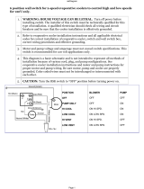
WARNING
Electric shock hazard. Can cause personal injury or equipment damage.
This equipment must be properly grounded. Connections and service to the
MicroTech II control panel must be performed only by personnel that are
knowledgeable in the operation of the equipment being controlled.

McQuay OM 920-1 5
Introduction
Getting Started
This manual contains information designed to assist the field technician with unit setup. The
technician will need to be familiar with the following topics at a minimum to successfully set
up unit operation.
• Keypad navigation/editing/passwords
• Control Mode
• Occ Mode
• DSP Setpoint
• BSP Setpoint
• Heat/Cool Changeover (Zone Setpoints)
• DAT Clg Setpoint
• DAT Htg Setpoint
• Clg Enable (OAT/EWT lockout)
• Htg Enable (OAT lockout)
• Econo Enable (Changeover temp/Enthalpy switch)
• Ventilation Limit/OA damper
WARNING
Excessive moisture in the control panel can cause hazardous working
conditions and improper equipment operation.
When servicing this equipment during rainy weather, the electrical
components in the main control panel must be protected from the rain.
CAUTION
Extreme temperature hazard. Can cause damage to system components.
The MicroTech III controller is designed to operate in ambient temperatures
from -20°F to 125°F. It can be stored in ambient temperatures from -40°F to
140°F. It is designed to be stored and operated in relative humidity up to 95%
(non-condensing).
CAUTION
Static sensitive components. A static discharge while handling
electronic circuit boards can cause damage to the components.
Discharge any static electrical charge by touching the bare metal inside the
main control panel before performing any service work. Never unplug any
cables, circuit board terminal blocks, relay modules, or power plugs while
power is applied to the panel.

6 McQuay OM 920-1
Using the Keypad/Display
Using the Keypad/Display
The keypad/display consists of a 5-line by 22 character display, three keys and a “push and
roll” navigation wheel. There is an Alarm Button, Menu (Home) Button, and a Back Button.
The wheel is used to navigate between lines on a screen (page) and to increase and decrease
changeable values when editing. Pushing the wheel acts as an Enter Button.
Figure 1: Keypad Controls
The first line on each page includes the page title and the line number to which the cursor is
currently “pointing”. The line numbers are X/Y to indicate line number X of a total of Y lines
for that page. The left most position of the title line includes an “up” arrow to indicate there
are pages “above” the currently displayed items, a “down” arrow to indicate there are pages
“below” the currently displayed items or an “up/down” arrow to indicate there are pages
“above and below” the currently displayed page.
Each line on a page can contain status only information or include changeable data fields.
When a line contains status only information and the cursor is on that line all but the value
field of that line is highlighted meaning the text is white with a black box around it. When the
line contains a changeable value and the cursor is at that line, the entire line is highlighted.
Each line on a page may also be defined as a “jump” line, meaning pushing the navigation
wheel will cause a “jump” to a new page. An arrow is displayed to the far right of the line to
indicate it is a “jump” line and the entire line is highlighted when the cursor is on that line.
The keypad/display Information is organized into five main menus or menus groups; Alarm
Lists Menu, System Summary Menu, Standard Menus, Extended Menus and Advance Menus.
Note – Only menus and items that are applicable to the specific unit configuration are displayed.
The Alarm Lists Menu includes active alarm and alarm log information. The System
Summary Menu includes status information indicating the current operating condition of the
unit. Standard Menus include basic menus and items required to setup the unit for general
operation. These include such things are control mode, occupancy mode and heating and
cooling setpoints. Extended Menus include more advanced items for “tuning” unit operation
such as PI loop parameters and time delays. Advanced Menus include the most advanced
items such as “unit configuration” parameters and service related parameters. These generally
do not needing changing or accessing unless there is a fundamental change to or a problem
with the unit operation.
3/23
System Summary
Advanced Menus
Alarm Lists
Unit State= Cooling
Clg Capacity=
25%

McQuay OM 920-1 7
Using the Keypad/Display
Passwords
When the keypad/display is first accessed, the Home Key is pressed, the Back Key is pressed
multiple times, or if the keypad/display has been idle for the Password Timeout timer (default
10 minutes), the display will show a “main” page where the user can enter a password or
continue without entering a password. The three password levels available are Level 2, Level
4, and Level 6, with Level 2 having the highest level of access. Entering the Level 6 password
allows access to the Alarm Lists Menu, System Summary Menu, and the Standard Menus
group. Entering the Level 4 password allows similar access to Level 6 with the addition of the
Extended Menus group. Entering the Level 2 password allows similar access to Level 4 with
the addition of the Advanced Menus group. The Level 2 password is 6363, the Level 4 is
2526, and the Level 6 password is 5321. Continuing without entering one of these three levels
allows access only to the Alarm Lists Menu and the System Summary Menu.
Note – Alarms can be acknowledged without entering a password.
Figure 2: Password Main Page
The password field initially has a value **** where each * represents an adjustable field.
These values can be changed by entering the Edit Mode described below.
Figure 3: Password Entry Page
Entering an invalid password has the same effect as continuing without entering a password.
Once a valid password has been entered, the controller allows further changes and access
without requiring the user to enter a password until either the password timer expires or a
different password is entered. The default value for this password timer is 10 minutes. It is
changeable from 3 to 30 minutes via the Timer Settings menu in the Extended Menus.
1/3McQuay AHU
Enter Password
Continue W/O Password
Version Information
1/1
Enter Password
Enter Password
***
*

8 McQuay OM 920-1
Using the Keypad/Display
Navigation Mode
In the Navigation Mode, when a line on a page contains no editable fields all but the value
field of that line is highlighted meaning the text is white with a black box around it. When the
line contains an editable value field the entire line is inverted when the cursor is pointing to
that line.
When the navigation wheel is turned clockwise, the cursor moves to the next line (down) on
the page. When the wheel is turned counter-clockwise the cursor moves to the previous line
(up) on the page. The faster the wheel is turned the faster the cursor moves.
When the Back Button is pressed the display reverts back to the previously displayed page. If
the Back button is repeated pressed the display continues to revert one page back along the
current navigation path until the “main menu” is reached.
When the Menu (Home) Button is pressed the display reverts to the “main page.”
When the Alarm Button is depressed, the Alarm Lists menu is displayed.
Edit Mode
The Editing Mode is entered by pressing the navigation wheel while the cursor is pointing to a
line containing an editable field. Once in the edit mode pressing the wheel again causes the
editable field to be highlighted. Turning the wheel clockwise while the editable field is
highlighted causes the value to be increased. Turning the wheel counter-clockwise while the
editable field is highlighted causes the value to be decreased. The faster the wheel is turned the
faster the value is increased or decreased. Pressing the wheel again cause the new value to be
saved and the keypad/display to leave the edit mode and return to the navigation mode.
Service Timers
A user may override timers for a period of up to 240 minutes by setting the Service Timer to a
non-zero number. When the Service Timer is not zero, the times listed below are set to the
Service Time (Default = 20 seconds) instead of the normal values. This allows the unit to be
run through its operating states without having to wait for the normal time delays to expire.
These times revert to the standard values when the Service Time count down to zero or is set
to zero by the user.
The affected times are:
• Cooling Stage Time
• Heating Stage Time
• Start Initial Time
• Recirculation
• ZeroOATime
Rapid Start
The user may elect to initiate a rapid startup sequence at unit power up by setting the Rapid
Start flag to Yes. When this flag is set to Yes, the Service Timer is set to 10 minutes whenever
the power is reset to the controller.

McQuay OM 920-1 9
Using the Keypad/Display
Manual Control
A user may manually control outputs to check operation of components when Manual Control
is set to ManCtrl. When Manual Control is set to ManCtrl, the unit is disabled and the unit is
shut down in the normal manner if it is operating. Outputs listed in the Manual Control menu
of the Keypad/Display section can then be controlled directly until Manual Control is set to
Normal.
Note – Manual Control will be set to No automatically after 240 minutes so that a person could not
put the unit into Manual Mode control and walk away from the unit and let it run at the
manual settings.
When Manual Control is set to Yes, the Control Mode is set to Off so that the unit will not
restart automatically.
When Manual Control is set to Normal all digital outputs in the Manual Control menu are set
to Off and all the analog outputs are set to 0.0% so that all outputs are in the Off or minimum
position when Manual Control is set to ManCtrl.
All alarms except those listed below are overridden during Manual Control.
During manual control, the unit will respond in the normal manner to the following alarms.
• Emergency Stop Fault
• Duct High Limit
• High Return Temperature
• High Discharge Temperature
• Low Discharge Temperature
• High Pressure - Circuit # 1
• High Pressure - Circuit # 2
• Low Pressure - Circuit # 1
• Low Pressure - Circuit # 2

10 McQuay OM 920-1
Keypad/Display Menu Structure
Keypad/Display Menu Structure
The following is a description of the MicroTech III menu structure. These menus and items
can all be displayed with the keypad/display. Menu items displayed will change based on the
selected unit configuration. Keypad/display menus are divided into 1) System Summary
menu - password required. 2) Standard menu - password not required. 3) Extended Menu -
higher level password required. 4) Advanced Menu - requires the highest level password.
Figure 4: Keypad/Display Menu Structure

McQuay OM 920-1 11
Keypad/Display Menu Structure

12 McQuay OM 920-1
Keypad/Display Menu Structure
System Summary Menu
Menus in the System Summary category contain basic unit operating status and control set
point parameters. The items shown in the System Summary Menu are Read Only and are not
adjustable from this menu. The following are brief descriptions of the System Summary
category menus and items. No password is required to view the System Summary Menu.
Unit State is a status only item which indicates the state of operation in which the unit is
currently operating. The unit can be in any of the operating states shown.
Clg Capacity is a status only item which indicates the percentage of the unit maximum
cooling capacity currently operating.
OAD/Econo Cap is a status only item which indicates the percentage that the outdoor damper
or economizer valve is currently open.
Htg Capacity is a status only item which indicates the percentage of the unit maximum
heating capacity currently operating.
Reheat Cap is a status only item which indicates the percentage of the unit maximum reheat
capacity currently operating.
Control Temp is a status only item which displays the current value of the “Control
Temperature.” The “Control Temperature” is defined as the temperature input selected by the
Control Temperature Source parameter. For example, if the Control Temperature Source
parameter is set to “Return,” then the Control Temperature parameter reads the same value as
the Return Air parameter.
Zone Clg Spt is a status only item which indicates the temperature in which the unit will go
into the cooling mode of operation.
Zone Htg Spt is a status only item which indicates the temperature in which the unit will go
into the heating mode of operation.
Table 2: System Summary Menu
Menu Display Name
Default
Setting
Range
Password
Level
Unit State= - Off None
Start
Recirc
FanOnly
MinDAT
Htg
Econo
Clg
Clg Capacity= - 0-100% None
OAD/Econo Cap= - 0-100% None
Htg Capacity= - 0-100% None
Reheat Cap= - 0-100% None
Control Temp= - -50.0-200.0°F None
Zone Clg Spt= - 0.0-100.0°F None
Zone Htg Spt= - 0.0-100.0°F None
Disch Air= - -50.0-250.0°F None
DAT Clg Spt= - 40.0-100.0°F None
DAT Htg Spt= - 40.0-140.0°F None
Min DAT Limit= - 0.0-70.0°F None
SAF Speed= - 0-100% None
DSP - 0.2-4.0in None
DuctSP Spt= - 0.2-4.0in None
RF/EF Speed= - 0-100% None
BSP - -0.25-0.25in None
BldgSP Spt= - -0.25-0.25in None
OA Temp= - -50.0-200.0°F None
EW Temp= - -50.0-150.0°F None
Rel Humidity= - 0-100% None

McQuay OM 920-1 13
Keypad/Display Menu Structure
Disch Air is a status only item which displays the current temperature reading from the unit's
discharge air temperature sensor (DAT). This sensor is standard on all units.
DAT Clg Spt is a status only item which indicates the temperature that the DAT should be
maintained at when it is in the cooling mode of operation.
DAT Htg Spt is a status only item which indicates the temperature that the DAT should be
maintained at when in the heating mode of operation.
Min DAT Limit is a status only item which indicates the discharge air low limit temperature
on CAV zone control units. Heating will be activated to maintain this setting when the
discharge temperature falls below it during the Fan Only operating state. On VAV or CAV
discharge control units, the minimum discharge temperature limit is the DAT Clg Spt.
SAFSpeed is a status only item which indicates the capacity of the supply air fan.
DSP is a status only item which displays the current duct static pressure reading.
DuctSP Spt= is a status only item which indicates the duct static pressure set point used for
controlling the VFD for the supply air fan. The VFD is modulated to maintain the duct
pressure at this value.
RF/EF Speed is a status only item indicating the capacity of the return fan/exhaust air fans.
BSP is a status only item which displays the current building static pressure reading.
BldgSP Spt is a status only item which indicates the building static pressure set point used for
controlling the return/exhaust fan VFD. The return/exhaust fan VFD is modulated to maintain
the building static pressure sensor input to this value.
OA Temp is a status only item which displays the current temperature reading from the unit
mounted outdoor air temperature sensor. This sensor is standard on all units.
EW Temp is a status only item that displays the current temperature reading from the unit
mounted entering water temperature sensor. The sensor is standard on all water-cooled units.
Rel Humidity is a status only item that displays the current relative humidity reading from the
optional humidity sensor.

14 McQuay OM 920-1
Keypad/Display Menu Structure
Standard Menus
The Standard Menus are menu items that control the unit's day to day operation. The menus
provide information about the units operation and its control parameters. Accessing the
Standard Menus requires the operator to enter the four-digit level 6 password, (5321) using the
keypad buttons located on the controller interface.
Table 3: Standard Menus
Menu Display Name Item Display Name Default Setting Range Password Level
Standard Menu System 6
Occupancy 6
Temperatures 6
Flow Summary 6
SAF Spd Control 6
RF/EF Spd Control 6
Cooling 6
Head Pressure 6
Evap Condensing 6
Economizer 6
Min OA Damper 6
Heating 6
Energy Recovery 6
Dehumidification 6
Daily Schedule 6
One Event Schedule 6
Holiday Schedule 6
Optimal Start 6
Operating Hours 6

McQuay OM 920-1 15
Keypad/Display Menu Structure
System Menu
The “System” menu provides a summary of basic unit status and control items. This menu
summarizes the current operating state of the unit, giving the operating state the unit is in,
along with the current capacity level of that operating state.
Table 4: System Menu
Menu Display Name Item Display Name Default Setting Range Password Level
System Unit State = - Off 6
Start
Recirc
FanOnly
MinDAT
Htg
Econo
Clg
Unit Status = - Enable 6
OffMan
OffMnCtl
OffNet
OffAlm
OffFnRty
Dehum Status= - Inactive 6
Active
Ctrl Mode = Off Off 6
HeatOnly
CoolOnly
FanOnly
HeatCool
Auto
Clg Status = - Enabled 6
None
OffAmb
OffAlarm
OffNet
OffMan
Htg Status = - Enabled 6
None
OffAmb
OffAlarm
OffNet
OffMan
Econo Status = - Enabled 6
None
OffAmb
OffAlarm
OffNet
OffMan
OffDehum
Clg Capacity= - 0-100% 6
Htg Capacity= - 0-100% 6
Reheat Cap= - 0-100% 6
SAF Speed = - 0-100% 6
RF/EF Speed = - 0-100% 6
OAD/Econo Cap= - 0-100% 6
Rel Humidity= - 0-100% 6
Emerg Mode= Normal Normal 6
Off
Net App Mode= Auto Off 6
HeatOnly
CoolOnly
FanOnly
Auto

16 McQuay OM 920-1
Keypad/Display Menu Structure
Unit State is a status only item which indicates the state of operation in which the unit is
currently operating.
Unit Status is a status only item which indicates the current operating status.
Dehum Status is a status only item which indicates whether or not Dehumidification is
currently active.
Ctrl Mode is an adjustable item which allows the unit to be set for off, auto heating/cooling
operation, cooling only, heating only, and fan only.
Clg Status is a status only item which indicates whether or not mechanical cooling is currently
allowed. If cooling is disabled, the reason is indicated.
Htg Status is a status only item which indicates whether or not heating is currently allowed. If
heating is disabled, the reason is indicated.
Econo Status is a status only item which indicates whether or not the economizer is currently
enabled. If economizer is enabled, the reason is indicated.
Clg Capacity is a status only item which indicates the percentage of the unit maximum
cooling capacity currently operating.
Htg Capacity is a status only item which indicates the percentage of the unit maximum
heating capacity currently operating.
Reheat Cap is a status only item which indicates the percentage of the unit maximum reheat
capacity currently operating.
SAF Speed is a status only item which indicates the current speed of the supply air fan.
RF/EF Speed is a status only item which indicates the current speed of the return fan/exhaust
air fans.
OAD/Econo Cap is a status only item which indicates the percentage that the outdoor
damper/waterside economizer valve is currently open.
Rel Humidity is a status only item that displays the current relative humidity reading from the
optional humidity sensor.
Emerg Mode is an adjustable item which indicates if the unit was shut down in an emergency
situation via a network command.
Net App Mode is a network adjustable item which indicates that the unit is set for network
off, cooling only, heating only, fan only or auto heating/cooling operation via a network signal.
This item has no affect on the unit operation unless the Ctrl Mode item is set to “Auto.”

McQuay OM 920-1 17
Keypad/Display Menu Structure
Occupancy Menu
Menus in the Occupancy menu contain status and control items that relate to unit
occupied/unoccupied operation.
Occupancy is a status only item which indicates whether the unit is currently in an occupied,
unoccupied, or tenant override mode of operation.
OccMode is an adjustable item which allows the unit to be set for manual occupied or
unoccupied operation, automatic operation based on a time schedule input or manual bypass
operation.
OccSrc is a status only item which indicates the input source or function that is responsible for
setting the Occupancy parameter to “Occ.”
UnoccSrc is a status only item which indicates the input source or function that is responsible
for setting the Occupancy parameter to “Unocc.”
Tnt Ovrd Time is an adjustable item which indicates the amount of time remaining for unit
operation since tenant override operation was activated.
Table 5: Occupancy Menu
Menu Display Name Item Display Name Default Setting Range Password Level
Occupancy Occupancy= Occ 6
Unocc
TntOvrd
Occ Mode= Auto Occ 6
Unocc
TntOvrd
Auto
OccSrc= - None 6
NetSchd
IntSchd
OneEvnt
RemoteSw
OccManCmd
OccMode
TStatTO
ManTO
UnoccSrc= - UnoccDehum 6
UnoccClg
UnoccHtg
IntOptStrt
NetOptStrt
None
Tnt Ovrde Time= 0 0-300min 6

18 McQuay OM 920-1
Keypad/Display Menu Structure
Temperature Menu
Menus in the Temperatures menu contain unit temperature status information.
Control Temp is a status only item which indicates what the current control temperature is.
Disch Air is a status only item which displays the current temperature reading from the unit's
discharge air temperature sensor (DAT). This sensor is standard on all units.
Return Air is a status only item which displays the current temperature reading from the
unit's return air temperature sensor (RAT). This sensor is standard on all units.
Space Temp is a status only item which displays the current space (or zone) temperature
reading from the optional unit space air temperature sensor input. If an optional space
temperature sensor is not installed, the SpaceT Present= item in the Setup menu should be set
to “No” to disable the alarm function associated with an open circuit at the space temperature
sensor input.
OA Temp is a status only item which displays the current temperature reading from the unit
mounted outdoor air temperature sensor. This sensor is standard on all units.
EFT/LCT (RTU) is a status only item which displays the current entering fan/leaving coil
temperature reading from the unit mounted temperature sensor. This sensor is available on
RTU units with dehumidification capability. This sensor is also installed on units equipped
with either gas or electric heat and is used by the controller to calculate the heat rise across the
heat exchanger by comparing it to the discharge air temperature input. The controller uses this
information to protect the heat exchanger against overheating.
EWT (SCU) is a status only item that displays the current temperature reading from the unit
mounted entering water temperature sensor. The sensor is standard on all water-cooled units.
MAT (SCU) is a status only item that displays the current temperature reading from the unit
mounted mixed air temperature sensor. The sensor is standard on all Self Contained units.
Table 6: Temperature Menu
Menu Display Name Item Display Name Default Setting Range Password Level
Temperatures Control Temp= - -50.0-200.0°F 6
Disch Air= - -50.0-250.0°F 6
Return Air= - -20.0-200.0°F 6
Space Temp= - -0.0-150.0°F 6
OA Temp= - -50.0-200.0°F 6
EFT/LC Temp= - -50.0-250.0°F 6
EW Temp= - -50.0-150.0°F 6
Mixed Air= - -50.0-250.0°F 6

McQuay OM 920-1 19
Keypad/Display Menu Structure
Flow Summary Menu
Airflow is a status only item that indicates whether or not discharge airflow is detected.
Airflow status is sensed by a binary input delivered to the controller by a differential pressure
switch (PC7). On VAV units duct static pressure is also a factor in the indication of airflow.
Waterflow is a status only item that indicates whether or not water flow is detected. Water
flow status is sensed by a binary input delivered to the controller by an optional water flow
sensor (WF1).
Water pump is a status only item that indicates whether or not the Pump Start Output is
active. The pump start output is available for field use to start a field supplied pump when
water flow is required. For field wiring requirements for using this output refer to “Field
Wiring” in the MicroTech III Installation Manual (IM 919). The Pump Start Output is turned
on whenever the economizer bypass valve is open, the unit is in the Econo or Cooling
operating state, economizer flush mode is active or a Freeze fault or Freeze problem alarm is
active or has been active within the past 10 minutes. Otherwise the Pump Start Output is off.
Supply Fan is a status only item which indicates whether or not the controller is commanding
the unit supply fan on.
Ret/Exh Fan is a status only item which indicates whether or not the controller is
commanding the unit RF/EF fan on.
FanOp is a status only item which indicates whether this output (MCB DO10) is On or Off.
Table 7: Flow Summary Menu
Menu Display Name Item Display Name Default Setting Range Password Level
Flow Summary Airflow = - NoFlow 6
Flow
Waterflow= - NoFlow 6
Flow
Water Pump= - Off 6
On
Supply Fan= - Off 6
On
Ret/Exh Fan= - Off 6
On
FanOp= - Off 6
On

20 McQuay OM 920-1
Keypad/Display Menu Structure
Supply Fan Speed Menu
SAF Speed is a status only item that indicates the current supply fan speed.
Speed Cmd is a status only item that indicates the current supply fan VFD commanded speed.
Duct Press is a status only item which indicates the current pressure of the supply air
ductwork. The duct pressure is measured at the location in which the duct static pressure tap
was field installed. This device is not factory installed.
DuctSP SPT is an adjustable item which sets the duct static pressure set point used for
controlling the VFD for the supply air fan. The VFD is modulated to maintain the duct
pressure at this value.
SAF Ctrl is an adjustable parameter used to select how the supply fan is to be controlled. The
supply fan can be controlled by supply air fan by duct pressure or by a percentage of supply
air fan speed from 25% to 100%. The speed option is typically used with a building
automation system.
Remote SF Cap is an adjustable item for setting the supply fan speed by the keypad or by a
network control signal.
Return/Exhaust Fan Speed Menu
RF/EF Speed a status only item that indicates the current return/exhaust fan VFD speed.
Speed Cmd is a status only item that indicates the current return/exhaust fan VFD
commanded speed.
Min Speed is a status only item that indicates the minimum return/exhaust fan VFD speed.
Bldg Press is a status only item which indicates the building static pressure at the building
static pressure sensor location.
BldgSP Spt is an adjustable item which sets the building static pressure set point used for
controlling the VFD for the return/exhaust air fan. The VFD is modulated to maintain the
building pressure at this value.
RF/EF CP Ctrl is an adjustable parameter used to select how the return/exhaust fans are to be
controlled. The exhaust fans can be controlled by the building pressure or by a percentage of
return/exhaust air fan speed from 25% to 100%. The speed option is typically used with a
building automation system.
Table 8: Supply Fan Speed Menu
Menu Display Name Item Display Name Default Setting Range Password Level
SAF Spd Control SAF Speed= - 0-100% 6
Speed Cmd= - 0-100% 6
Duct Press= - 0.0-5.0in 6
DuctSP Spt= 1.0in 0.2-4.0in 6
SAF Ctrl= DSP DSP 6
Speed
Rem SAF Cap= 25% 0-100% 6
Table 9: Return/Exhaust Fan Speed Menu
Menu Display Name Item Display Name Default Setting Range Password Level
RF/EF Spd Control RF/EF Speed= - 0-100% 6
Speed Cmd= - 0-100% 6
Min Speed = 5% 0-100% 6
Bldg Press= - -0.25-0.25in 6
BldgSP Spt= 0.050in -0.25-0.25in 6
RF/EF Ctrl= Tracking None 6
Tracking
BldgP
Speed
Rem RAF Cap= 5% 0-100% 6
Rem ExhF Cap= 5% 0-100% 6
/