Page is loading ...

BENCH MODEL MULTIMETER
I
Contents
Contents ........................................................................................................................................................................................... I
Chapter 1 ......................................................................................................................................................................................... 1
Safety Standards .............................................................................................................................................................................. 1
Warning ........................................................................................................................................................................................... 1
Warranty .......................................................................................................................................................................................... 2
Chapter 2 ......................................................................................................................................................................................... 3
Introduction and Specifications ....................................................................................................................................................... 3
Front Panel ...................................................................................................................................................................................... 3
Rear Panel ....................................................................................................................................................................................... 7
LCD Display Description ................................................................................................................................................................ 9
Function Descriptions .................................................................................................................................................................... 10
Chapter 3 Operation Manual ....................................................................................................................................................... 11
Understanding AC Zero Input Behavior of True RMS Meters ...................................................................................................... 11
DC/AC(TRMS) Voltage ................................................................................................................................................................ 11
DCmV/ACmV ............................................................................................................................................................................... 13
Ohm/Continuity/DIODE ............................................................................................................................................................... 14
Capacitance Measurement ............................................................................................................................................................. 15
Logic Frequency/Duty cycle Measurement ................................................................................................................................... 16
Clamp Measurement...................................................................................................................................................................... 17
Temperature measurement ............................................................................................................................................................. 19

II
DCμA / AcμA measurement .......................................................................................................................................................... 20
DC mA / AC mA measurement ..................................................................................................................................................... 21
DC A / AC A measurement ............................................................................................................................................................ 22
Linear Frequency Measurement .................................................................................................................................................... 23
Relative Measurement ................................................................................................................................................................... 24
Max/Min Value .............................................................................................................................................................................. 25
Data Hold ...................................................................................................................................................................................... 25
Low Passed Filter .......................................................................................................................................................................... 25
Peak Value ..................................................................................................................................................................................... 26
RS232 Interface ............................................................................................................................................................................. 26
Auto Power Off ............................................................................................................................................................................. 26
Chapter 4 Specification ................................................................................................................................................................ 27
General Specification .................................................................................................................................................................... 27
Range and Accuracy ...................................................................................................................................................................... 27
Chapter 5 Maintenance ................................................................................................................................................................ 33
Introduction ................................................................................................................................................................................... 33
Replacing the Fuse ........................................................................................................................................................................ 33
Replacing the Power Fuse ............................................................................................................................................................. 34
Replacing the Battery .................................................................................................................................................................... 34
Chapter 6 Accessories ................................................................................................................................................................... 35

BENCH MODEL MULTIMETER
1
Chapter 1
Safety Standards
This style of digital multimeter is designed and manufactured according to the safety requirements set out by the
IEC61010-1 standards for electronic test instruments . Its design and manufacture is strictly based on the provisions in the
1000V CAT II of IEC61010-1 and the Stipulation of 2-Pollution Grade.
Warning
To avoid possible electric shock, personal injury, or death, read the following before using the Meter:
Use the Meter only as specified in this manual, or the protection provided by the Meter might be impaired.
Do not use the Meter in wet environments.
Inspect the Meter before using it. Do not use the Meter if it appears damaged.
Inspect the test leads before use. Do not use them if insulation is damaged or metal is exposed. Check the test leads for
continuity. Replace damaged test leads before using the Meter.
Verify the Meter's operation by measuring a known voltage before and after using it. Do not use the Meter if it operates
abnormally. Protection may be impaired. If in doubt, have the Meter serviced.
Whenever it is likely that safety protection has been impaired, make the Meter inoperative and secure it against any
unintended operation.
Have the Meter serviced only by qualified service personnel.
Do not apply more than the rated voltage, as marked on the Meter, between the terminal or between any terminal and
earth ground.

Error! Use the Home tab to apply 标题 2 to the text that you want to appear here.
2
Always use the power cord and connector appropriate for the voltage and outlet of the country or location in which you
are working.
Remove test leads from the Meter before opening the case.
Never remove the cover or open the case of the Meter without first removing it from the main power source.
Never operate the Meter with the cover removed or the case open.
Use only the replacement fuses specified by the manual.
Use the proper terminal, function and range for your measurements.
Do not operate the Meter around explosive gas, vapor or dust.
When using probes, keep your fingers behind the finger guards.
When making electrical connections, connect the common test lead before connecting the live test lead. When
disconnecting, disconnect the live test lead before disconnecting the common test lead.
Disconnect circuit power and discharge all high voltage capacitors before testing resistance, continuity, diodes, or
capacitance.
Before measuring current, check the Meter's fuses and turn OFF power to the circuit before connecting the Meter to the
circuit.
When servicing the Meter, use only specified replacement parts.
Warranty
The meter is warranted to be free from defects in material and workmanship under normal use and service. The warranty
period is one year and begins on the date of shipment. Parts, product repairs, and services are warranted for 18 months except
for misused, altered, neglected, contaminated, or damaged by accident or abnormal conditions of operation or handling.This

BENCH MODEL MULTIMETER
3
warranty does not apply to fuses, disposable batteries.
Chapter 2
Introduction and Specifications
22000 Counts
ACV and DCV up to 1000V
10μV Sensitivity for Voltage measurement.
Linear Frequency 、Logic Frequency and Duty Measurement
Capacity Range from 0.01nF to 220mF
AC TRMS.
Peak Max/Min value Measurement Function
Max/Min,Relative Measurement Function
Low Passed Filter Function
RS-232 Optical Isolation Interface
PC Software for Display Data Record and Data Analysis
Power Supply Methods: 220V/110V AC(50~60Hz)、9V 6F22 Battery、1.5×6 AA Battery
Temperature Measurement
Clamp Measurement
Front Panel
Front panel as below:

Error! Use the Home tab to apply 标题 2 to the text that you want to appear here.
4
Front Panel Features
1. VΩHz Terminal
Input positive terminal for all measurement except current measurement , connected with red test leads.

BENCH MODEL MULTIMETER
5
2. COM Terminal
Input common terminal for all measurement , connected with black test leads.
3. μA/mA Terminal
Input positive terminal for current measurement (μA/mA) , connected with red test lead.
4. A Terminal
Input positive terminal for current measurement (A) , connected with red test lead.
5. Rotary Switch
Switching positions correspondingly when changing different input signals.
Note: Switching position before changing signals in case caused damage.
6. Display Screen
7. Button
Button Description
Name
Description
FUNC
Function toggling
Back Light(Wake up), press this button can wake the meter in auto power off mode
RANGE
Toggle to manual mode in autorange mode , increase range in manual mode;toggle to autorange mode when
pressing longer than 1 S in manual mode.
Hz
Under frequency measurement, toggle from frequency to duty.
HOLD
Select hold function.,when the measuing value overload ,Display ‘OL’;
PEAK
Select peak function: The peak values are stored in external Capacitors.
MAX/MIN
Select max/min function: The meter displays the maximum or minimum value.
LPF
To activate the low passed filter function, most of noise above 1KHz will decay greatly.
RELΔ
LCD panel displays relative value.

Error! Use the Home tab to apply 标题 2 to the text that you want to appear here.
6
Name
Description
PC-LINK
LCD panel displays ‘RS232’ , the meter communicates with PC software.
FUNC button description
Rotary Position
Input Signal
DCV ACV
DCmV ACmV
DCA ACA
TEMP
DCμA ACμA
DCmA ACmA
DCA ACA
Button description
RANGE
HOLD
MAX/MIN
REL
Hz
PEAK
(Note 2)
LPF
PCLINK
(Note 1)
Voltage
○
○
○
○
○
○
○
○
○
Current
○
○
○
○
○
○
○
○
Clamp
○
○
○
○( AC)
○
○
○
○
Resistance
○
○
○
○
○
X
○
Capacitance
○
○
○
○
○
X
○
Frequency
X
○
X
X
○
○
○

BENCH MODEL MULTIMETER
7
RANGE
HOLD
MAX/MIN
REL
Hz
PEAK
(Note 2)
LPF
PCLINK
(Note 1)
Duty
X
○
X
X
○
X
○
Temperature
X
○
○
○
○
X
○
Note 1: In Capacitance Measureing mode ,when MAX/MIN or REL function is activated,the data sent to PC software is the
actual value.
Note 2: When PEAK function is activated, the data sent to PC software is invalid
Note 3: ○ meaning the function can be selected, X menaing the function is invalid
Rear Panel
Rear panel as blow:

Error! Use the Home tab to apply 标题 2 to the text that you want to appear here.
8
(1) Battery Cover
Replace 9V 6F22 or 1.5×6 AA battery.
(2) Supply Power Inlet with Fuse, Houses Fuse 0.1A/250V.
(3) Power Switch
(4) RS232 Socket

BENCH MODEL MULTIMETER
9
LCD Display Description
(1) Bargraph Display Zone
(2) Digital Display Zone
Display Annunciators and Indicators
Sign
Description
Battery (low battery when shown on display.)

Error! Use the Home tab to apply 标题 2 to the text that you want to appear here.
10
Sign
Description
Auto power off function is selected
DC (Direct Current)
AC (Alternating Current)
Hold status is selected
Diode test is selected
Continuity test is selected
RS232
Communication with PC terminal is selected
P-MIN
Reading is minimum peak value
P-MAX
Reading is maximum peak value
REL
Relative readings function is selected
MIN
Reading is minimum value
MAX
Reading is maximum value
Function Descriptions
Auto range or manual range:Toggle to manual mode in autorange mode , increase range in manual mode;toggle to
autorange mode when pressing longer than 1 S in manual mode.
Linear frequency :When input signal is AC voltage or current, press ‘Hz’ button to activate frequency measurement.
Logic frequency and duty : In frequency mode, press ‘Hz’ button switches the mode to/from duty cycle mode.
Continuity and diode test:Under continuity test , the beeper emits a continuous tone if the input is approximately below
30Ω.Under diode test,the forward voltage of the semiconductor junction (or junctions) is measured.
Relative measurement: Show the difference between actual value and the relative base.

BENCH MODEL MULTIMETER
11
Display Value = Actual Value — Relative Value.
Max/Min:Show the minimum or maximum value recorded and the present measurement.
Low passed filter:Most of noise above 1KHz will decay greatly. So obtain more stable and accurate readings on low
frequency response.
Peak hold: Hold Max and Min peak value.
RS232 Interface.
Chapter 3 Operation Manual
Understanding AC Zero Input Behavior of True RMS Meters
True RMS Meters accurately measure distorted waveforms, but when the input leads are shorted together in the AC
function the Meter displays a residual reading between 0 and 30 counts, When the test leads are open, the display reading may
fluctuate due to interference, These offset reading are normal .they do not affect the meter’s measurement accuracy over the
specified measurement range.
DC/AC(TRMS) Voltage
The Meter is capable of measuring voltage up to 1000 V DC and 750 V AC.
To perform a voltage measurement:
1. Turn rotary switch to position,LCD panel displays‘DC’; press FUNC button when measuring AC voltage,
and LCD display ‘AC’;
2. Connect red test lead with VΩHz terminal and black test lead with COM terminal;

Error! Use the Home tab to apply 标题 2 to the text that you want to appear here.
12
3. Connect test leads to test circuit;
4. The Meter selects the appropriate range in the autorange mode. The function and measurement are displayed;
5. By pressing the RANGE button, it is possible to select range manually. While displaying OL during manual range
measurement, it is necessary to select a larger range. When OL displaying under the maximum range, it indicates
the voltage exceeding 1000V,so it is necessary to remove both the red and black test leads from the measured circuit
immediately.
Note: In case of probe hanging in the air, the voltage inducted by the testing line may cause unstable readings on the
display screen, but that will not affect the accuracy of measurement.

BENCH MODEL MULTIMETER
13
DCmV/ACmV
The Meter is capable of measuring mV up to 220mV.
To perform a mV measurement:
1. Turn rotary switch to position,LCD panel displays‘DC’; press FUNC button when measuring AC mV, and
LCD display ‘AC’;
2. Connect red test lead with VΩHz terminal and black test lead with COM terminal;
3. Connect test leads to test circuit;
4. The function and measurement are displayed;
5. While displaying OL during measurement, it is necessary to remove both the red and black test leads from the
measured circuit immediately.
Notes: In case of probe hanging in the air, the voltage inducted by the testing line may cause unstable readings on the
display screen, but that will not affect the accuracy of measurement.
Note: Do not measuring the voltage exceed the 220mV voltage.

Error! Use the Home tab to apply 标题 2 to the text that you want to appear here.
14
Ohm/Continuity/DIODE
The Meter is capable of measuring Ohm up to 220MΩ.
To perform a measurement:
1. Turn rotary switch to Ωposition,LCD panel displays‘Ω’; press FUNC button to select continuity function or
diode function;
2. Connect red test lead with VΩHz terminal and black test lead with COM terminal;
3. Press FUNC button selecting a function of the ohm、continuity or diode。
4. Connect test leads to test circuit;
5. The function and measurement are displayed;

BENCH MODEL MULTIMETER
15
6. The beeper emits a continuous tone if the input is approximately below 30Ω.Under diode test,The forward voltage
of the semiconductor junction is measured.
Note: In case of performing resistance or continuity test on circuit board, it is necessary firstly to turn off the power of
the circuit board and then perform the measurement. As there may be other parallel circuits, so the displayed
value of test is not surely the actual value of the resistance.
Capacitance Measurement
The Meter is capable of measuring up to 220mF
To perform a capacitance measurement:
1. Turn rotary switch to position,LCD panel display‘F’;

Error! Use the Home tab to apply 标题 2 to the text that you want to appear here.
16
2. Connect red test lead with VΩHz terminal and black test lead with COM terminal;
3. Connect test leads to measure capacitance;
4. The function and measurement are displayed
Notes: 1). Discharge the capacitance before measuring.
2). Do not to perform capacitance measurement on a circuit board on which there are other parallel devices, for
that may cause a very large error.
Logic Frequency/Duty cycle Measurement
The measurement frequency up to 220MHz(Vpp 3V),duty cycle range is of 10%~90%
To perform the measurement:
1. Turn rotary switch to Hz position,LCD panel displays‘Hz’;

BENCH MODEL MULTIMETER
17
2. Connect red test lead with VΩHz terminal and black test lead with COM terminal;
3. Connect test leads to measuring circuit;
4. Pressing Hz button to toggle between frequency and duty cycle measurement;
5. The function and measurement are displayed.
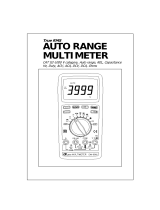
Clamp Measurement
The Meter is capable of measuring current up to 2200A
To perform the measurement:
1. Turn rotary switch to position,LCD panel displays‘DC’; press FUNC button when measuring AC Current,
and LCD display ‘AC’;

Error! Use the Home tab to apply 标题 2 to the text that you want to appear here.
18
2. Connect red test lead with VΩHz terminal and black test lead with COM terminal;
3. Connect test leads to clamp adapter’s output terminal ;
4. The Meter selects the appropriate range in the autorange mode. The function and measurement are displayed;
5. By pressing the RANGE button it is possible to select range manually. While displaying OL during manual range
measurement, it is necessary to select a larger range. When OL displaying under the maximum range, it indicates
the voltage exceeding 2200A,so it is necessary to remove both the red and black test leads from the adapter output
terminal immediately.
Note: It is required clamp adapter output 1mV/A
/