Page is loading ...

Reference Manual
00809-0200-4728, Rev SD
March 2021
Rosemount
™
644 Temperature Transmitter
with HART
®
Protocol

Safety messages
NOTICE
Read this document before working with the product. For personal and system safety, and for optimum product performance,
make sure you thoroughly understand the contents before installing, using, or maintaining this product. For technical assistance,
contacts are listed below:
Customer Central
Technical support, quoting, and order-related questions.
United States - 1-800-999-9307 (7:00 am to 7:00 pm Central Time)
Asia Pacific- 65 777 8211
Europe/Middle East/Africa - 49 (8153) 9390
North American Response Center
Equipment service needs.
1-800-654-7768 (24 hours—includes Canada)
Outside of these areas, contact your local Emerson representative.
WARNING
Follow instruction
Failure to follow these installation guidelines could result in death or serious injury.
Ensure only qualified personnel perform the installation.
Explosion
Explosions could result in death or serious injury.
Do not remove the connection head cover in explosive atmospheres when the circuit is live.
Before connecting a handheld communicator in an explosive atmosphere, ensure that the instruments in the loop are
installed in accordance with intrinsically safe or non-incendive field wiring practices.
Verify that the operating atmosphere of the transmitter is consistent with the appropriate hazardous locations certifications.
All connection head covers must be fully engaged to meet explosion-proof requirements.
Process leaks
Process leaks could result in death or serious injury.
Do not remove the thermowell while in operation.
Install and tighten thermowells and sensors before applying pressure.
Electric shock
Electrical shock could cause death or serious injury.
Use extreme caution when making contact with the leads and terminals.
The products described in this document are NOT designed for nuclear-qualified applications.
Using non-nuclear qualified products in applications that require nuclear-qualified hardware or products may cause inaccurate
readings.
For information on Rosemount nuclear-qualified products, contact your local Emerson Sales Representative.
Physical access
Unauthorized personnel may potentially cause significant damage to and/or misconfiguration of end users’ equipment. This could
be intentional or unintentional and needs to be protected against.
Physical security is an important part of any security program and fundamental to protecting your system. Restrict physical access
by unauthorized personnel to protect end users’ assets. This is true for all systems used within the facility.
2

CAUTION
Conduit/cable entries
The conduit/cable entries in the transmitter housing use a ½–14 NPT thread form.
When installing in a hazardous location, use only appropriately listed or Ex certified plugs, glands, or adapters in cable/conduit
entries.
Unless otherwise marked, the conduit/cable entries in the housing enclosure use a ½–14 NPT form. Only use plugs, adapters,
glands, or conduit with a compatible thread form when closing these entries.
Unless marked, the conduit/cable entries in the transmitter housing use a ½–14 NPT thread form. Entries marked “M20” are
M20 × 1.5 thread form. On devices with multiple conduit entries, all entries will have the same thread form. Only use plugs,
adapters, glands, or conduit with a compatible thread form when closing these entries.
Only use plugs, adapters, glands, or conduit with a compatible thread form when closing these entries.
3

4

Contents
Chapter 1 Introduction.............................................................................................................. 7
1.1 Using this manual........................................................................................................................ 7
Chapter 2 Configuration...........................................................................................................11
2.1 Overview................................................................................................................................... 11
2.2 Safety messages........................................................................................................................ 11
2.3 System readiness.......................................................................................................................12
2.4 Configuration methods..............................................................................................................13
2.5 Verify configuration...................................................................................................................18
2.6 Basic configuration of the transmitter........................................................................................20
2.7 Configure dual sensor options................................................................................................... 26
2.8 Configure device outputs...........................................................................................................33
2.9 Inputting device information..................................................................................................... 40
2.10 Configure measurement filtering.............................................................................................42
2.11 Diagnostics and service............................................................................................................44
2.12 Establishing multi-drop communication..................................................................................49
2.13 Using the transmitter with the HART Tri-Loop..........................................................................51
2.14 Transmitter security ................................................................................................................54
Chapter 3 Hardware Installation.............................................................................................. 57
3.1 Overview................................................................................................................................... 57
3.2 Safety messages........................................................................................................................ 57
3.3 Considerations...........................................................................................................................58
3.4 Installation procedures.............................................................................................................. 61
Chapter 4 Electrical Installation................................................................................................73
4.1 Overview................................................................................................................................... 73
4.2 Safety messages........................................................................................................................ 73
4.3 Wiring and powering the transmitter.........................................................................................74
Chapter 5 Operation and Maintenance.....................................................................................85
5.1 Overview................................................................................................................................... 85
5.2 Safety messages........................................................................................................................ 85
5.3 Calibration overview.................................................................................................................. 87
5.4 Sensor input trim....................................................................................................................... 88
5.5 Trim the analog output..............................................................................................................91
5.6 Transmitter-sensor matching.................................................................................................... 93
5.7 Switching HART Revision........................................................................................................... 95
Chapter 6 Troubleshooting...................................................................................................... 97
6.1 Overview................................................................................................................................... 97
Reference Manual Contents
00809-0200-4728 March 2021
Emerson.com/Rosemount 5

6.2 Safety messages........................................................................................................................ 97
6.3 4–20 mA/HART output.............................................................................................................. 99
6.4 Diagnostic messages............................................................................................................... 101
6.5 Return of materials.................................................................................................................. 106
Chapter 7 Safety Instrumented Systems (SIS) Certification..................................................... 107
7.1 SIS certification........................................................................................................................107
7.2 Safety certified identification................................................................................................... 107
7.3 Installation...............................................................................................................................107
7.4 Configuration.......................................................................................................................... 108
7.5 Operation and maintenance.................................................................................................... 109
7.6 Specifications.......................................................................................................................... 111
Appendix A Reference Data.......................................................................................................113
A.1 Product certifications.............................................................................................................. 113
A.2 Ordering information, specifications, and drawings.................................................................113
A.3 AMS terms...............................................................................................................................114
Appendix B Field Communicator Menu Trees and Fast Keys.......................................................115
B.1 Field Communicator menu trees..............................................................................................115
B.2 Field Communicator Fast Keys................................................................................................. 121
Appendix C Local Operator Interface (LOI)................................................................................ 125
C.1 Number entry.......................................................................................................................... 126
C.2 Text entry................................................................................................................................ 127
C.3 Timeout...................................................................................................................................129
C.4 Saving and canceling............................................................................................................... 129
C.5 LOI menu tree..........................................................................................................................131
C.6 LOI menu tree – extended menu............................................................................................. 132
Contents Reference Manual
March 2021 00809-0200-4728
6 Emerson.com/Rosemount

1 Introduction
1.1 Using this manual
This manual is designed to assist in the installation, operation, and maintenance of
Rosemount 644 Head Mount, Field Mount, and Rail Mount Transmitters with the HART
®
protocol.
Configuration provides instruction the commissioning and operating the Rosemount 644
HART Transmitter. The information explains how to configure software functions and
many configuration parameters on an Asset Management System, a Field Communicator,
and the Local Operator Interface display option.
Hardware Installation contains mechanical installation instructions for the transmitter.
Electrical Installation contains electrical installation instructions and considerations for the
transmitter.
Operation and Maintenance contains common operation and maintenance techniques for
the transmitter.
Troubleshooting provides troubleshooting techniques for the most common transmitter
operating problems.
Safety Instrumented Systems (SIS) Certification provides identification, installation,
configuration, operation and maintenance, and inspection information for Safety
Instrumented Systems as it pertains to the Rosemount 644 Head Mount and Field Mount
Temperature Transmitter.
Reference Data supplies procedure on how to get the specifications, ordering information,
and product certification.
Field Communicator Menu Trees and Fast Keys contains Field Communicator menu trees
and Field Communicator Fast Keys.
Local Operator Interface (LOI) contains instructions for number entry, text entry, as well as
the LOI menu tree and LOI extended menu tree.
1.1.1
Transmitter overview
The Rosemount 644 Head Mount and Field Mount Temperature Transmitters support the
following features:
• HART
®
configuration with Selectable HART revision capability (Revisions 5 or 7)
• Accepts either one or two inputs from a wide variety of sensor types (2-, 3-, and 4-wire
RTD, thermocouple, mV and ohm)
• A compact transmitter size with electronics completely encapsulated in protective
silicone and enclosed in a plastic housing ensuring long-term transmitter reliability
• Optional Safety Certification Option (IEC 61508 SIL 2)
• Optional enhanced accuracy and stability performance
• Optional LCD display with extended temperature ratings of -40 to 185 °F (-40 to 85 °C)
Reference Manual
Introduction
00809-0200-4728 March 2021
Emerson.com/Rosemount 7

• Optional advanced LCD display with local operator interface (LOI)
• The Rosemount 644 Head Mount Transmitter is available in two housing materials
(Aluminum and SST) and various housing options that allow for mounting flexibility in a
variety of environmental conditions. The Rosemount 644 Field Mount is available in an
aluminum housing.
• Special dual-sensor features include Hot Backup
™
, Sensor Drift Alert, first good,
differential and average temperature measurements, and four simultaneous
measurement variable outputs in addition to the analog output signal.
• Additional advanced features include: Thermocouple degradation diagnostic, which
monitors thermocouple health, and process and transmitter minimum/maximum
temperature tracking.
The Rosemount 644 Rail Mount Temperature Transmitter supports the following features:
• 4–20 mA/HART protocol (Revision 5)
• Accepts one sensor input from a wide variety of sensor types (2-, 3-, and 4-wire RTD,
Thermocouple, mV and ohm)
• Completely encapsulated electronics to ensure long term transmitter reliability
Refer to the following literature for a full range of compatible connection heads, sensors,
and thermowells provided by Emerson.
• Rosemount Volume 1 Temperature Sensors and Accessories (English) Product Data
Sheet
• Rosemount DIN-Style Temperature Sensors and Thermowells (Metric) Product Data
Sheet
Table 1-1 and Table 1-2 below summarize changes in the Rosemount 644 Head Mount and
Rail Mount HART device revisions, respectively.
Table 1-1: Head Mount HART Revisions
Software
release date
Identify device Field device driver
Review
instructions
NAMUR
software
revision
NAMUR
hardware
revision
(1)
HART
software
revision
HART
universal
revision
(2)
Device
revision
Manual
document
number
Feb-2020 1.1.xx 1.0.xx 4
7 9
00809-0200-
4728
5 8
Aug-2012 1.1.xx 1.0.xx 3 7 9
00809-0200-
4728
(1) NAMUR Software Revision is located in the hardware tag of the device. HART Software Revision
can be read using a HART-capable configuration tool.
(2) Device Driver file names use Device and DD Revision ( e.g. 10_07). HART Protocol is designed to
enable legacy driver revisions to continue to communicate with new HART devices. To access this
functionality, the new device driver must be downloaded. It is recommended to download the
new device driver to ensure new functionality.
Introduction Reference Manual
March 2021 00809-0200-4728
8 Emerson.com/Rosemount

Table 1-2: Rail Mount HART Revisions
Railmount
Rosemount 644 Hardware revision 31
Device revision 7
HART revision 5
Reference Manual Introduction
00809-0200-4728 March 2021
Emerson.com/Rosemount 9

Introduction Reference Manual
March 2021 00809-0200-4728
10 Emerson.com/Rosemount

2 Configuration
2.1 Overview
This section contains information on commissioning and tasks that should be performed
on the bench prior to installation. Field Communicator, AMS Device Manager, and Local
Operator Interface (LOI) instructions are given to perform configuration functions. For
convenience, Field Communicator Fast Key sequences are labeled “Fast Keys,” and
abbreviated LOI menus are provided for each function below. The LOI is only available on
the Rosemount 644 Head Mount and Field Mount designs, and the configuration
instructions referencing the interface will not apply to the rail mount form factor.
Full Field Communicator menu trees and Fast Key sequences are available in Field
Communicator Menu Trees and Fast Keys. Local operator interface menu trees are
available in Local Operator Interface (LOI).
2.2 Safety messages
Instructions and procedures in this section may require special precautions to ensure the
safety of the personnel performing the operations. Refer to the following safety messages
before performing an operation preceded by this symbol.
WARNING
Follow instruction
Failure to follow these installation guidelines could result in death or serious injury.
Ensure only qualified personnel perform the installation.
Explosion
Explosions could result in death or serious injury.
Do not remove the connection head cover in explosive atmospheres when the circuit is
live.
Before connecting a handheld communicator in an explosive atmosphere, ensure that
the instruments in the loop are installed in accordance with intrinsically safe or non-
incendive field wiring practices.
Verify that the operating atmosphere of the transmitter is consistent with the
appropriate hazardous locations certifications.
All connection head covers must be fully engaged to meet explosion-proof
requirements.
Process leaks
Process leaks could result in death or serious injury.
Do not remove the thermowell while in operation.
Install and tighten thermowells and sensors before applying pressure.
Reference Manual Configuration
00809-0200-4728 March 2021
Emerson.com/Rosemount 11

WARNING
Electric shock
Electrical shock could cause death or serious injury.
Use extreme caution when making contact with the leads and terminals.
Physical access
Unauthorized personnel may potentially cause significant damage to and/or
misconfiguration of end users’ equipment. This could be intentional or unintentional and
needs to be protected against.
Physical security is an important part of any security program and fundamental to
protecting your system. Restrict physical access by unauthorized personnel to protect end
users’ assets. This is true for all systems used within the facility.
2.3 System readiness
2.3.1 Confirm HART revision capability
If using HART
®
-based control or asset management systems, confirm the HART capability
of those systems prior to transmitter installation. Not all systems are capable of
communicating with HART Revision 7 protocol. This transmitter can be configured for
either HART Revision 5 or 7.
For instructions on how to change the HART revision of your transmitter, see Switching
HART Revision.
Configuration Reference Manual
March 2021 00809-0200-4728
12 Emerson.com/Rosemount

2.3.2 Confirm correct device driver
• Verify the latest Device Driver files are loaded on your systems to ensure proper
communications.
• Download the latest Device Driver at Emerson.com/Rosemount or Fieldcomm.org.
Table 2-1: Rosemount 644 Device Revisions and Files
Software date Identify device Find device driver files
Review
instructions
Review
functionality
Date
NAMUR
software
revision
HART
®
software
revision
HART
Universal
revision
(1)
Device
revision
(2)
Document
Changes to
software
(3)
June 2012 1.1.1 01
5 8 Rosemount
644
Temperature
Transmitter
Reference
Manual
See
(3)
for list of
changes
7 9
(1) NAMUR Software Revision is located on the hardware tag of the device. HART Software Revision can be read using a
HART Communication tool.
(2) Device Driver file names use Device and DD Revision (e.g. 10_01). HART Protocol is designed to enable legacy device
driver revisions to continue to communicate with new HART devices. To access new functionality, the new Device Driver
must be downloaded. It is recommended to download the new Device Driver files to ensure full functionality.
(3) HART Revision 5 and 7 Selectable. Dual Sensor support, Safety Certified, Advanced Diagnostics (if ordered), Enhanced
Accuracy, and Stability (if ordered).
2.3.3
Surges/transients
The transmitter will withstand electrical transients of the energy level encountered in
static discharges or induced switching transients. However, high-energy transients, such
as those induced in wiring from nearby lightning strikes, welding, heavy electrical
equipment, or switching gears, can damage both the transmitter and the sensor. To
protect against high-energy transients, install the transmitter into a suitable connection
head with the integral transient protector, option T1. Refer to the Rosemount 644 Product
Data Sheet for more information.
2.4 Configuration methods
CAUTION
Commisioning
Set all transmitter hardware adjustments during commissioning to avoid exposing the
transmitter electronics to the plant environment after installation.
The transmitter can be configured either before or after installation. Configuring the
transmitter on the bench using either a Field Communicator, AMS Device Manager, or LOI
ensures all transmitter components are in working order prior to installation.
Reference Manual Configuration
00809-0200-4728 March 2021
Emerson.com/Rosemount 13

The transmitter can be configured either on-line or off-line using a Field Communicator,
AMS Device Manager, or the optional LOI (head-mount and field-mount). During on-line
configuration, the transmitter is connected to a Field communicator. Data is entered in
the working register of the communicator and sent directly to the transmitter.
Off-line configuration consists of storing configuration data in a Field Communicator while
it is not connected to a transmitter. Data is stored in nonvolatile memory and can be
downloaded to the transmitter at a later time.
2.4.1 Configuring on the bench
To configure on the bench, required equipment includes a power supply, a digital
multimeter (DMM), and Field Communicator, AMS Device Manager, or a LOI – option M4.
Connect the equipment as shown in Figure 2-1. Connect HART
®
Communication leads at
any termination point in the signal loop. To ensure successful HART Communication, a
resistance of at least 250 ohms must be present between the transmitter and the power
supply. Connect the Field Communicator leads to the clips behind the power (+,–)
terminals on the top of the device. Avoid exposing the transmitter electronics to the plant
environment after installation by setting all transmitter jumpers during the
commissioning stage on the bench.
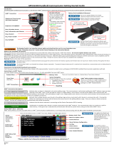
Figure 2-1: Powering the Transmitter for Bench Configuration
Head mount and Field mount Rail mount
A
B
C
D
E
A
B
C
D
E
+
+
+
+
_
_
_
_
A. Field communicator
B. Power supply
C. 248 Ω ≤ RL ≤ 1100 Ω
D. Recorder (optional)
E. Ammeter (optional)
Note
• Signal loop may be grounded at any point or left ungrounded.
• A Field Communicator may be connected at any termination point in the signal loop.
The signal loop must have between 250 and 1100 ohms load for communications.
• Max torque is 6 in-lb (0.7 N-m).
Configuration Reference Manual
March 2021 00809-0200-4728
14 Emerson.com/Rosemount

2.4.2 Selecting a configuration tool
Field Communicator
The Field Communicator is a handheld device that exchanges information with the
transmitter from the control room, the instrument site, or any wiring termination point in
the loop. To facilitate communication, connect the Field Communicator, shown in this
manual, in parallel with the transmitter (see Figure 2-1). Use the loop connection ports on
the rear panel of the Field Communicator. The connections are non-polarized. Do not
make connections to the serial port or the nickel cadmium (NiCd) recharger jack in
explosive atmospheres. Before connecting the Field Communicator in an explosive
atmosphere make sure the instruments in the loop are installed in accordance with
intrinsically safe or non-incendive field wiring practices.
There are two interfaces available with the Field Communicator: Traditional and
Dashboard interfaces. All steps using a Field Communicator will be using Dashboard
interfaces. Figure 2-2 shows the Device Dashboard interface. As stated in System
readiness, it is critical that the latest DD’s are loaded into the Field Communicator for
optimal transmitter performance.
Visit Emerson.com/Rosemount to download latest DD library.
Turn on the Field Communicator by pressing the ON/OFF key. The Field Communicator will
search for a HART
®
-compatible device and indicate when the connection is made. If the
Field Communicator fails to connect, it indicates that no device was found. If this occurs,
refer to Troubleshooting.
Figure 2-2: Field Communicator Device Dashboard Interface
Field Communicator menu trees and Fast Keys are available in Field Communicator Menu
Trees and Fast Keys
AMS Device Manager
With an AMS Device Manager software package, you can commission and configure
instruments, monitor status and alerts, troubleshoot from the control room, perform
advanced diagnostics, manage calibration, and automatically document activities with a
single application.
Full configuration capability with AMS Device Manager requires loading the most current
Device Descriptor (DD) for this device. Download the latest DD at Emerson.com/
Rosemount or Fieldcomm.org.
Reference Manual Configuration
00809-0200-4728 March 2021
Emerson.com/Rosemount 15

Note
All steps listed in this product manual using AMS Device Manager assume the use of
Version 11.5.
Local Operator Interface (LOI)
• The LOI requires option code M4 to be ordered.
• To activate the LOI, push either configuration button. Configuration buttons are
located on the LCD display (remove the housing cover to access the interface. See
Table 2-2 for configuration button functionality and Figure 2-3 for configuration button
location.)
When using the LOI for configuration, several features require multiple screens for a
successful configuration. Data entered will be saved on a screen-by-screen basis; the LOI
will indicate this by flashing SAVED on the LCD display each time.
Note
Entering into the LOI menu effectively disables the ability to write to the device by any
other host or configuration tool. Ensure this is communicated to necessary personnel
before using the LOI for device configuration.
Figure 2-3: LOI Configuration Buttons
A. Configuration buttons
Table 2-2: LOI Button Operation
Button
Left No SCROLL
Right Yes ENTER
Configuration Reference Manual
March 2021 00809-0200-4728
16 Emerson.com/Rosemount

LOI password
An LOI password can be entered and enabled to prevent review and modification of device
configuration via the LOI. This does not prevent configuration from HART
®
or through the
control system. The LOI password is a four-digit code that is to be set by the user. If the
password is lost or forgotten the master password is “9307”. The LOI password can be
configured and enabled/disabled by HART communication via a Field Communicator, AMS
Device Manager, or the LOI.
2.4.3 Setting the loop to manual
When sending or requesting data that would disrupt the loop or change the output of the
transmitter, set the process application loop to manual. The Field Communicator, AMS
Device Manager, or LOI will prompt you to set the loop to manual when necessary.
Acknowledging this prompt does not set the loop to manual. The prompt is only a
reminder; set the loop to manual as a separate operation.
2.4.4
Failure mode
As part of normal operation, each transmitter continuously monitors its own performance.
This automatic diagnostics routine is a timed series of checks repeated continuously. If
diagnostics detect an input sensor failure or a failure in the transmitter electronics, the
transmitter drives its output to low or high depending on the position of the failure mode
switch. If the sensor temperature is outside the range limits, the transmitter saturates its
output to 3.9 mA for standard configuration on the low end (3.8 mA if configured for
NAMUR-compliant operation) and 20.5 mA on the high end (or NAMUR-compliant). These
values are also custom configurable by the factory or using the Field Communicator. The
values to which the transmitter drives its output in failure mode depend on whether it is
configured to standard, NAMUR-compliant, or custom operation. See Rosemount 644
Temperature Transmitter Product Data Sheet for standard and NAMUR-compliant
operation parameters.
2.4.5
HART software lock
The HART
®
software lock prevents changes to the transmitter configuration from all
sources; all changes requested via HART by the Field Communicator, AMS Device manager
or the LOI will be rejected. The HART Lock can only be set via HART Communication, and is
only available in HART Revision 7 mode. The HART Lock can be enabled or disabled with a
Field Communicator or AMS Device Manager.
Lock HART software using the Field Communicator
From the HOME screen, enter the Fast Key sequence.
Device Dashboard Fast Keys
3, 2, 1
Lock HART software using the AMS Device Manager
Procedure
1. Right click on the device and select Configure.
Reference Manual Configuration
00809-0200-4728 March 2021
Emerson.com/Rosemount 17

2. Under Manual Setup select the Security tab.
3. Select the Lock/Unlock button under HART Lock (Software) and follow the screen
prompts.
2.5 Verify configuration
It is recommended that various configuration parameters are verified prior to installation
into the process. The various parameters are detailed out for each configuration tool.
Depending on what configuration tool(s) are available, follow the steps listed relevant to
each tool.
2.5.1 Verify configuration using the Field Communicator
Configuration parameters listed in Table 2-3 below are the basic parameters that should
be reviewed prior to transmitter installation. A full list of configuration parameters that
can be reviewed and configured using a Field Communicator are located in Field
Communicator Menu Trees and Fast Keys. A Rosemount 644 Device Descriptor (DD) must
be installed on the Field Communicator to verify configuration.
Verify device configuration using Fast Key sequences in Table 2-3.
From the HOME screen, enter the Fast Key sequences listed in Table 2-3.
Table 2-3: Device Dashboard Fast Key Sequences
Function HART 5 HART 7
Alarm Values 2, 2, 5, 6 2, 2, 5, 6
Damping Values 2, 2, 1, 5 2, 2, 1, 6
Lower Range Value (LRV) 2, 2, 5, 5, 3 2, 2, 5, 5, 3
Upper Range Value (URV) 2, 2, 5, 5, 2 2, 2, 5, 5, 2
Primary Variable 2, 2, 5, 5, 1 2, 2, 5, 5, 1
Sensor 1 Configuration 2, 1, 1 2, 1, 1
Sensor 2 Configuration
(1)
2, 1, 1 2, 1, 1
Tag 2, 2, 7, 1, 1 2, 2, 7, 1, 1
Units 2, 2, 1, 5 2, 2, 1, 4
(1) Available only if option code (S) or (D) is ordered.
Configuration Reference Manual
March 2021 00809-0200-4728
18 Emerson.com/Rosemount

2.5.2 Verify configuration using the AMS Device Manager
Procedure
1. Right click on the device and select Configuration Properties from the menu.
2. Navigate the tabs to review the transmitter configuration data.
2.5.3 Verify configuration using the LOI
Procedure
1. Press any configuration button to activate the LOI.
2. Select VIEW CONFIG to review the below parameters.
3. Use the configuration buttons to navigate through the menu.
The parameters to be reviewed prior to installation include:
• Tag
• Sensor configuration
• Units
• Alarm and saturation levels
• Primary variable
• Range values
• Damping
2.5.4
Checking transmitter output
Before performing other transmitter on-line operations, review the transmitter digital
output parameters to ensure that the transmitter is operating properly and is configured
to the appropriate process variables.
Checking or setting process variables
The “Process Variables” menu displays process variables, including sensor temperature,
percent of range, analog output, and terminal temperature. These process variables are
continuously updated. The default primary variable is Sensor 1. The secondary variable is
the transmitter terminal temperature by default.
Check or set process variables using the Field Communicator
From the HOME screen, enter the Fast Key sequence.
Device Dashboard Fast Keys
3, 2, 1
Reference Manual Configuration
00809-0200-4728 March 2021
Emerson.com/Rosemount 19

Check or set process variables using the AMS Device Manager
Procedure
• Right click on the device and select Service Tools from the menu.
The Variables tab displays the following process variables:
— Primary, second, third, and fourth variables, as well as the analog output.
Check or set process variables using LOI
Procedure
1. To check the process variables from the LOI, the user must first configure the
display to show the desired variables (see Configuring the LCD display).
2. Once the desired device variables are chosen, simply exit the LOI menu and view the
alternating values on the display screen.
Figure 2-4: Check or set process variables using LOI
ON/OFF
VIEW CONFIG
ZERO TRIM
UNITS
RERANGE
LOOP TEST
DISPLAY
EXTENDED MENU
EXIT MENU
SENSOR 1
SENSOR 2*
ANALOG
PV
AVG
1
ST
GOOD
DIFF
% RANGE
TERM
MNMAX1*
MNMAX2*
MNMAX3*
MNMAX4*
BACK TO MENU
EXIT MENU
2.6 Basic configuration of the transmitter
The transmitter must be configured for certain basic variables in order to be operational.
In many cases, all of these variables are pre-configured at the factory. Configuration may
be required if the transmitter is not configured or if the configuration variables need
revision.
Configuration Reference Manual
March 2021 00809-0200-4728
20 Emerson.com/Rosemount
/